Code Check for Structural Steel Members
Steel Structures according to Eurocode 3
Structural steel code properties
Section Class and Reduction Factors Calculation
Checking of Members in Axial Tension
Checking of Members in Axial Compression
Checking of Members under Bending Moment
Checking of Members under Shear Force
Checking of Members under Bending Moment and Shear Force
Checking of Members under Bending Moment and Axial Force
Checking of Members under Bending, Shear and Axial Force
Checking for Buckling of Members in Compression
Checking for Lateral-Torsional Buckling of Beams Subjected to Bending
Checking for Lateral-Torsional Buckling of Members Subjected to Bending and Axial Compression
Critical Forces and Moments Calculation.
Steel Structures According to AISC ASD/LRFD 14th Ed.
Structural steel code properties
Checking of Members for Tension (Chapter D)
Checking of Members in Axial Compression (Chapter E)
Compressive Strength for Flexural Buckling
Compressive Strength for Flexural-Torsional Buckling
Compressive Strength for Flexure
Checking of Members for Shear (Chapter G)
Checking of Members for Combined Flexure and Axial Tension / Compression (Chapter H)
Checking of Members for Combined Torsion, Flexure, Shear and/or Axial Force (Chapter H)
Steel Structures According to AISC ASD/LRFD 15th Ed.
Structural steel code properties
Checking of Members for Tension (Chapter D)
Checking of Members in Compression (Chapter E)
Checking of Members for Flexure (Chapter F)
Checking of Members for Shear (Chapter G)
Checking of Members for Combined Flexure and Axial Tension / Compression (Chapter H)
Structural steel members are referred to steel beams structural element. These steel members are managed to be checked according to:
· Eurocode 3
· AISC 14th Edition
· AISC 15th Edition
The different checking types will be assigned on the Check properties from the Details window. The available checking types in CivilFEM ACT are:
|
Code |
Type of check |
|
|
Eurocode 3 |
Tension |
Bending + Axial Force |
|
Compression |
Bending + Shear + Axial Force |
|
|
Bending |
Compressing Buckling |
|
|
Shear |
Bending Buckling |
|
|
Bending + Shear |
Bending + Compression buckling |
|
|
AISC 14th Edition |
Tension |
Shear |
|
Compression flexural buckling |
Plate girder |
|
|
Compression flexural torsional buckling |
Bending + Axial Force |
|
|
Bending |
|
|
|
AISC 15th Edition |
Tension (Section D) |
Shear (Section G) |
|
Compression (Section E) |
Bending (Section F) |
|
|
Bending + Axial Force (Section H) |
|
|
The necessary properties for each of these checks will be assigned in that Check properties section, being properly explained on chapters ahead.
For checking steel structures according to Eurocode 3 in CivilFEM ACT, it is possible to check structures composed by welded or rolled shapes under axial forces, shear forces and bending moments in 3D. The calculations made by CivilFEM ACT correspond to the recommendations of Eurocode 3: Design of steel structures Part 1-1: General rules and rules for buildings (EN 1993-1-1:2005).
With CivilFEM ACT it is possible to accomplish the following check and analysis types:
|
Check steel sections subjected to |
|
|
- Tension |
Art. 6.2.3 |
|
- Compression |
Art. 6.2.4 |
|
- Bending |
Art. 6.2.5 |
|
- Shear force |
Art. 6.2.6 |
|
- Bending and Shear |
Art. 6.2.8 |
|
- Bending and axial force |
Art. 6.2.9 |
|
- Bending, shear and axial force |
Art. 6.2.10 |
|
Check for buckling |
|
|
- Compression members with constant cross-section |
Art. 6.3.1 |
|
- Lateral-torsional buckling of beams |
Art. 6.3.2 |
|
- Members subjected to bending and axial tension |
N/A |
|
- Members subjected to bending and axial compression |
Art. 6.3.3 |
Valid cross-sections supported by CivilFEM ACT for checks according to Eurocode 3 are the following:
· All rolled shapes included in the program libraries (see the hot rolled shapes library).
· The following welded beams: double T shapes, U or channel shapes, T shapes, box, equal and unequal legs angles and pipes.
· Structural steel sections defined by plates.
CivilFEM ACT considers the above sections as sections composed of plates; for example, an I Double T-section is composed by five plates: four flanges and one web. These cross sections are therefore adapted to the method of analysis of Eurocode 3. Obviously circular sections cannot be decomposed into plates, so these sections are analyzed separately.
With checks according to Eurocode 3, CivilFEM ACT includes three different coordinate reference systems. All of these systems are right-handed:
CivilFEM ACT Reference Axis. (XCF, YCF, ZCF).
Cross-Section Reference Axis. (XS, YS, ZS).
Eurocode 3 Reference Axis. (Code axis). (XEC3, YEC3, ZEC3).

For the Eurocode 3 axes system:
· The origin matches to the CivilFEM axes origin.
· XEC3 axis coincides with CivilFEM X-axis.
· YEC3 axis is the relevant axis for bending and its orientation is defined by the user (in steel check process).
· ZEC3 axis is perpendicular to the plane defined by X and Y axis, to ensure a right-handed system.
To define this reference system, the user must indicate which direction of the CivilFEM axis (-Z, -Y, +Z or +Y) coincides with the relevant axis for positive bending. The user may define this reference system when checking according to this code. In conclusion, the code reference system coincides with that of CivilFEM.
|
Relevant Axis for Bending in CivilFEM Reference System |
Angle of Rotation (clockwise) of Eurocode 3 Reference System respect to the CivilFEM Reference System |
|
- ZCF |
0 º (Default value) |
|
- YCF |
90 º |
|
+ ZCF |
180 º |
|
+ YCF |
-90 º |
For Eurocode 3 checking, the following material properties are used:
|
Description |
Property |
|
Steel yield strength |
Fy(th) |
|
Ultimate strength |
Fu(th) |
|
Partial safety factors |
gM0 gM1 gM2 |
|
Elasticity modulus |
E |
|
Poisson coefficient |
n |
|
Shear modulus |
G |
Eurocode 3 considers the following data set for the section:
· Gross section data
· Net section data
· Effective section data
· Data belonging to the section and plates class.
Gross section data correspond to the nominal properties of the cross-section. For the net section, only the area is considered. This area is calculated by subtracting the holes for screws, rivets and other holes from the gross section area. The area of holes is introduced within the structural steel code properties.
Effective section data and section and plates class data are obtained in the checking process according to the effective width method. For class 4 cross-sections, this method subtracts the non-resistance zones for local buckling. However, for cross-sections of a lower class, the sections are not reduced for local buckling.
In the following tables, the section data used in Eurocode 3 are shown:
|
Description |
Data |
|
Input data: 1.- Height 2.- Web thickness 3.- Flanges thickness 4.- Flanges width 5.- Distance between flanges 6.- Radius of fillet (Rolled shapes) 7.- Toe radius (Rolled shapes) 8.- Weld throat thickness (Welded shapes) 9.- Web free depth
|
H Tw Tf B Hi r1 r2 a d |
|
Output data |
(None) |
|
Description |
Data |
Reference axis |
|
Input data: 1.- Depth in Y 2.- Depth in Z 3.- Cross-section area 4.- Moments of inertia for torsion 5.- Moments of inertia for bending 6.- Product of inertia 7.- Elastic resistant modulus 8.- Plastic resistant modulus 9.- Radius of gyration 10.- Gravity center coordinates 11.- Extreme coordinates of the perimeter
12.- Distance between GC and SC in Y and in Z 13.- Warping constant 14.- Shear resistant areas 15.- Torsional resistant modulus 16.- Moments of inertia for bending about U, V 17.- Angle Y->U or Z->V
|
Tky tkz A It Iyy, Izz Izy Wely, Welz Wply, Wplz iy, iz Ycdg, Zcdg Ymin, Ymax, Zmin, Zmax Yms, Zms Iw Yws, Zws Xwt Iuu, Ivv a |
CivilFEM CivilFEM
CivilFEM CivilFEM CivilFEM CivilFEM CivilFEM CivilFEM Section Section
Section
CivilFEM CivilFEM Principal CivilFEM |
|
Output data: |
(None) |
|
The effective section depends on the section geometry and on the forces and moments that are applied to it. Consequently, for each element end, the effective section is calculated.
|
Description |
Data |
Reference axis |
|
Imput data: |
(None) |
|
|
Output data: 1.- Cross-section area 2.- Moments of inertia for bending 3.- Product of inertia 4.- Elastic resistant modulus 5.- Gravity center coordinates 6.- Distance between GC and SC in Y and in Z 7.- Warping constant 8.- Shear resistant areas |
Aeff Iyyeff, Izzeff Izyeff Wyeff, Wzeff Ygeff, Zgeff Ymseff, Zmseff Iw Yws, Zws |
CivilFEM CivilFEM CivilFEM Section Section
CivilFEM |
For Eurocode 3 checking, besides the section properties, more data are needed for buckling checks. These data are shown in the following table.
|
Description |
EN 1993-1-1:2005 |
|
Input data: |
|
|
1.- Unbraced length of member (global buckling). Length between lateral restraints (lateral-torsional buckling). |
L |
|
2.- Buckling effective length factors in XY, XZ planes YZ (Effective buckling length for plane XY =L*K XY ) (Effective buckling length for plane XZ =L*K XZ ). |
K XY, K XZ |
|
3.- Lateral buckling factors, depending on the load and restraint conditions. |
C1, C2, C3 |
|
4.- Equivalent uniform moment factors for flexural buckling. |
CMy, CMz |
|
5.- Equivalent uniform moment factors for lateral-torsional buckling. |
CMLt |
|
6.- Effective length factor regarding the boundar conditions. |
K |
|
7.- Warping effective factor. |
KW |
The checking process includes the evaluation of the following expression:

![]()
Evaluation steps:
1. Read the loading check requested by the user.
2. Read the CivilFEM axis to be considered as the relevant axis for bending so that it coincides with the Y axis of Eurocode 3. In CivilFEM, by default, the principle bending axis that coincides with the +Y axis of Eurocode 3 is the +Y.
3. The following operations are necessary for each selected element:
a.
Obtain material properties of the element stored
in CivilFEM database and calculate the rest of the properties needed for
checking:
Properties obtained from CivilFEM database:
Calculated properties:
Epsilon, material coefficient:
![]()
b. Obtain the cross-section data corresponding to the element.
c. Initialize values of the effective cross-section.
d. Initialize reduction factors of section plates and the rest of plate parameters necessary for obtaining the plate class.
e. If necessary for the type of check (check for buckling), calculate the critical forces and moments of the section for buckling: elastic critical forces for the XY and XZ planes and elastic critical moment for lateral-torsional buckling. (See section: Calculation of critical forces and moments).
f.
Obtain internal forces and moments: ![]() ,
, ![]() ,
, ![]() ,
, ![]() ,
, ![]() ,
, ![]() within the section.
within the section.
g. Specific section checking according to the type of external load. The specific check includes:
1. If necessary, selecting the forces and moments considered for the determination of the section class and used for the checking process.
2. Obtaining the cross-section class and calculating the effective section properties.
3. Checking the cross-section according to the external load and its class by calculating the check criterion.
h. Store the results.
Sections, according to Eurocode 3, are made up by plates. These plates can be classified according to:
1. Plate function: webs and flanges in Y and Z axis, according to the considered relevant axis of bending.
2. Plate union condition: internal plates or outstand plates.
For sections included in the program libraries, the information above is defined for each plate. CivilFEM classifies plates as flanges or webs according to their axis and provides the plate union condition for each end. Ends can be classified as fixed or free (a fixed end is connected to another plate and free end is not).
For checking the structure for safety, Eurocode 3 classifies sections as one of four possible classes:
|
Class 1 |
Cross-sections which can form a plastic hinge with the rotation capacity required for plastic analysis. |
|
Class 2 |
Cross-sections which can reach their plastic moment resistance, but have limited rotation capacity. |
|
Class 3 |
Cross-sections for which the stress in the extreme compression fiber of the steel member can reach the yield strength, but local buckling is liable to prevent the development of the plastic moment resistance. |
|
Class 4 |
Cross-sections for which it is necessary to make explicit allowances for the effects of local buckling when determining their moment resistance or compression resistance. |
The cross-section class is the highest (least favorable) class of all of its elements: flanges and webs (plates). First, the class of each plate is determined according to the limits of Eurocode 3. The plate class depends on the following:
1. The geometric width to thickness ratio with the plate width properly corrected according to the plate and shape type.
GeomRat = Corrected_Width / thickness
The width correction consists of subtracting the zone that does not contribute to buckling resistance in the fixed ends. This zone depends on the shape type of the section. Usually, the radii of the fillet in hot rolled shapes or the weld throats in welded shapes determine the deduction zone. The values of the corrected width that CivilFEM uses for each shape type include:
· Welded Shapes:
Double T section:
Internal webs or flanges:
Corrected width = d
d Web free depth
Outstand flanges:
|
Corrected width |
|
Where:
|
B |
Flanges width |
|
Tw |
Web thickness |
|
|
Radius of fillet |
T section:
Internal webs or flanges:
Corrected width = d
Outstand flanges:
Corrected width = B/d
C section:
Internal webs or flanges:
Corrected width = d
Outstand flanges:
|
Corrected width |
B – |
L section:
Corrected width
= ![]()
![]() Angle flange
width
Angle flange
width
Box section:
Internal webs:
Corrected width = H
H Height
Internal flanges:
Corrected
width ![]()
![]() Web thickness
Web thickness
Circular hollow section
Corrected width = H
· Rolled Shapes:
Double T section:
Internal webs or flanges:
Corrected width = d
d Web free depth
Outstand flanges:
Corrected width = B/2
B Flanges width
T Section:
Internal webs or flanges:
Corrected width = d
Outstand flanges:
Corrected width = B/2
C Section:
Internal webs or flanges:
Corrected width = d
Outstand flanges:
Corrected width = B
L Section:
Corrected width
= ![]()
![]() Angle flange
width
Angle flange
width
Box section:
Internal webs:
Corrected width = d
Internal flanges:
Corrected
width ![]()
![]() Flanges
thickness
Flanges
thickness
Pipe section:
Corrected width = H
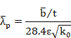
2.
The limit listed below for width to thickness
ratio. This limit depends on the material parameter e and the normal stress
distribution in the plate section. The latter value is given by the following
parameters: a, ![]() and k0,
and the plate type, internal or outstand; the outstand case depends on if the
free end is under tension or compression.
and k0,
and the plate type, internal or outstand; the outstand case depends on if the
free end is under tension or compression.
Limit
(class) ![]()
![]()
![]()
where:
|
a |
Compressed length / total length |
|
y |
|
|
|
Buckling factor |
|
|
The higher stress in the plate ends. |
|
|
The lower stress in the plate ends. |
A linear stress distribution on the plate is assumed.
The procedure to determine the section class is as follows:
1. Obtain stresses at first plate ends from the stresses applied on the section, properly filtered according to the check type requested by the user.
2.
Calculate the parameters: a, ![]() and k0
and k0
For internal plates:
|
|
ENV 1993-1-1:1992 |
EN 1993-1-1:2005 |
|
|
|
|
|
|
|
|
|
|
|
|
|
|
|
|
For outstand plates with an absolute value of the stress at the free end greater than the corresponding value at the fixed end:
For ![]()
![]()
For ![]()
![]() = infinite
= infinite
For outstand plates with an absolute value of the stress at the free end lower than the corresponding value at the fixed end:
For ![]()
![]()
For ![]()
![]()
For ![]()
![]() = infinite
= infinite
Cases in which ![]() infinite are not included in Eurocode 3. With these cases, the plate is
considered to be practically in tension and it will not be necessary to
determine the class. These cases have been included in the program to avoid
errors, and the value
infinite are not included in Eurocode 3. With these cases, the plate is
considered to be practically in tension and it will not be necessary to
determine the class. These cases have been included in the program to avoid
errors, and the value ![]() has been adopted
because the resultant plate class is 1 and the plate reduction factor is r = 1 (the same values as if the whole plate was in tension). The
reduction factor is used later in the effective section calculation.
has been adopted
because the resultant plate class is 1 and the plate reduction factor is r = 1 (the same values as if the whole plate was in tension). The
reduction factor is used later in the effective section calculation.
3.
Obtain the limiting proportions as functions of:
a, ![]() and k0 and
the plate characteristics (internal, outstand: free end in compression or
tension).
and k0 and
the plate characteristics (internal, outstand: free end in compression or
tension).
EN 1993-1-1:2005:
Internal plates:
|
|
for |
|
|
for |
|
|
for |
|
|
for |
|
|
for |
|
|
for |
Outstand plates, free end in compression:
|
|
|
|
|
|
Outstand plates, free end in tension:
|
|
|
|
|
|
Above is the general equation used by the program to obtain the limiting proportions for determining plate classes. In addition, plates of Eurocode 3 may be checked according to special cases.
For example:
In sections totally compressed:
a=
1; ![]() = 1 for all plates
= 1 for all plates
In sections under pure bending:
a =
0.5; ![]() = -1 for the web
= -1 for the web
a = 1; ![]() = 1 for compressed
flanges
= 1 for compressed
flanges
4. Obtain the plate class:
|
If |
|
GeomRat |
< Limit(1) |
Plate Class = 1 |
|
If |
Limit(1) ≤ |
GeomRat |
< Limit(2) |
Plate Class = 2 |
|
If |
Limit(2) ≤ |
GeomRat |
< Limit(3) |
Plate Class = 3 |
|
If |
Limit(3) ≤ |
GeomRat |
|
Plate Class = 4 |
Repeat these steps (1,2,3,4) for each section plate.
5.
Assign of the highest class of the plates to the
entire section.
In tubular sections, the section class is directly determined as if it were a
unique plate, with GeomRat and the Limits calculated as follows:
6. GeomRat = outer diameter/ thickness.
![]()
![]()
![]()
For class 4 sections, the section resistance is reduced, using the effective width method.
For each
section plate, the effective lengths at both ends of the plate and the
reduction factors ![]() and
and ![]() are calculated.
These factors relate the length of the effective zone at each plate end to its
width.
are calculated.
These factors relate the length of the effective zone at each plate end to its
width.
Effective_length_end 1 = ![]()
Effective_length_end 2 = ![]()
The following formula from Eurocode 3 has been implemented for this process:
![]()
1. Internal plates:
For ![]() (Both ends
compressed)
(Both ends
compressed)

![]()
![]()
![]()
![]()
![]()
![]() corrected plate width
corrected plate width
plate_width = real plate width
For ![]() (end 1 in
compression and end 2 in tension)
(end 1 in
compression and end 2 in tension)

![]()
![]()
![]()
![]()
![]()
2. Outstand plates:
For ![]() (Both ends in
compression: end 1 fixed, end 2 free)
(Both ends in
compression: end 1 fixed, end 2 free)

![]()
![]()
![]()
For ![]() (end 1 fixed and in
tension, end 2 free and in compression)
(end 1 fixed and in
tension, end 2 free and in compression)

![]()
![]()
![]()
For ![]() (end 1 fixed and in
compression, end 2 free and in tension)
(end 1 fixed and in
compression, end 2 free and in tension)

![]()
![]()
![]()
If end 2 is the fixed end, the
values ![]() and
and ![]() are switched.
are switched.
The global reduction factor r is obtained by as follows:
EN 1993-1-1:2005:
For internal compression elements
For ![]()

For ![]()
![]()
For outstands compression elements:
For ![]()

For ![]()
![]()
Both Eurocode define as the plate given by:
where:
![]() = corrected
plate width
= corrected
plate width
t = relevant thickness
e = material parameter
![]() = buckling factor
= buckling factor
To determine effective section properties, three steps are followed:
1.
Effective widths of flanges are calculated from factors α and ![]() these factors are
determined from the gross section properties. As a result, an intermediate
section is obtained with reductions taken in the flanges only.
these factors are
determined from the gross section properties. As a result, an intermediate
section is obtained with reductions taken in the flanges only.
2.
The resultant section properties are obtained
and factors α and ![]() are calculated
again.
are calculated
again.
3. Effective widths of webs are calculated so that the finalized effective section is determined. Finally, the section properties are recalculated once more.
The recalculated section properties are included in the effective section data table. Checking can be accomplished with the gross, net or effective section properties, according to the section class and checking type.
Each checking type follows a specific procedure that will be explained in the following sections.
Corresponds to chapter 6.2.3 in EN 1993-1-1:2005.
1. Forces and moments selection. The forces and moments considered for this checking type are:
![]() = FX Design value
of the axial force (positive if tensile, element not processed if compressive).
= FX Design value
of the axial force (positive if tensile, element not processed if compressive).
2.
Class definition and effective section
properties calculation.
For this checking type, the section class is always 1 and the considered
section is either the gross or net section.
3.
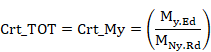
Criteria calculation.
For members under axial tension, the general criterion Crt_TOT is
checked at each section. This criterion coincides with the axial criterion Crt_N.
![]()
where ![]() is the design tension resistance of the cross-section, taken as the smaller
value of:
is the design tension resistance of the cross-section, taken as the smaller
value of:
|
|
plastic design strength of the gross cross-section
|
|
|
|
ultimate design strength of the net cross-section |
|
4. Output results are written in the ANSYS Workbench results file. Checking results: criteria and variables are described in the following table:
|
Result |
Concepts |
Description |
|
NED |
|
Design value of the tensile force (EN 1993-1-1:2005). |
|
NTRD |
|
Design tensile strength of the cross-section. |
|
CRT_N |
|
Axial criterion. |
|
CRT_TOT |
|
Eurocode 3 global criterion. |
|
NPLRD |
|
Design plastic strength of the gross cross-section. |
|
NURD |
|
Ultimate design strength |
Corresponds to chapter 6.2.4 in EN 1993-1-1:2005.
1. Forces and moments selection. The forces and moments considered for this checking type are:
![]() = FX Design
value of the axial force (positive if compressive, element not processed if
tensile).
= FX Design
value of the axial force (positive if compressive, element not processed if
tensile).
2. Class definition and effective section properties calculation.
The section class is determined by the general processing of the section with
the previously selected forces and moments if the selected option is partial or
with all the forces and moments if the selected option is full. The entire
calculation process is accomplished with the gross section properties.
3. Criteria calculation. For members in axial compression, the general criterion Crt_TOT is checked at each section. This criterion coincides with the axial criterion Crt_N:
![]()
where ![]() is the design compression resistance of the cross-section
is the design compression resistance of the cross-section
Class 1,2 or 3 cross-sections:
![]() design plastic
resistance of the gross section
design plastic
resistance of the gross section
Class 4 cross sections:
EN 1993-1-1:2005:
![]()
4. Output results written in the CivilFEM ACT checked file. Checking results: criteria and variables are described at the following table.
|
Result |
Concepts |
Description |
|
NED |
|
Design axial force (EN 1993-1-1:2005). |
|
NCRD |
|
Design compression strength of the cross-section. |
|
CRT_N |
|
Axial criterion. |
|
CRT_TOT |
|
Eurocode 3 global criterion. |
|
CLASS |
|
Section Class. |
|
AREA |
|
Area of the section (Gross or Effective). |
Corresponds to chapter 6.2.5 in EN 1993-1-1:2005.
1.
Forces and moments selection.
The forces and moments considered for this checking type are:
![]() Design value of the bending moment along the relevant axis for
bending.
Design value of the bending moment along the relevant axis for
bending.
2. Class definition and effective section properties calculation.
The section class is determined by the general processing of the section with
the previously selected forces and moments if the selected option is partial or
with all the forces and moments if the selected option is full. The entire
calculation process is accomplished with the gross section properties.
3.
Criteria calculation.
For members subjected to a bending moment in the absence of shear force, the
following condition is checked at each section:
where:
![]()
![]() design value of the
bending moment
design value of the
bending moment
![]() design moment
resistance of the cross-section
design moment
resistance of the cross-section
Class 1 or 2 cross-sections:
![]()
Class 3 cross sections:
![]()
Class 4 cross sections:
EN 1993-1-1:2005:
![]()
4. Output results are written in the CivilFEM ACT checked file. Checking results: criteria and variables are described in the following table.
|
Result |
Concepts |
Description |
|
MED |
|
Design value of the bending moment (EN 1993-1-1:2005). |
|
MCRD |
|
Design moment resistance of the cross-section. |
|
CRT_M |
|
Bending criterion. |
|
CRT_TOT |
|
Eurocode 3 global criterion. |
|
CLASS |
|
Section Class. |
|
W |
|
Used section modulus (Elastic, Plastic or Effective). |
Corresponds to chapter 6.2.6 in EN 1993-1-1:2005.
1. Forces and moments selection. The forces and moments considered for this checking type are:
![]() Design value
of the shear force perpendicular to the relevant axis of bending.
Design value
of the shear force perpendicular to the relevant axis of bending.
2. Class definition and effective section properties calculation. For this checking type, the section class is always 1 and the effective section is the gross section.
3. Criteria calculation. With members under shear force, the following condition is checked at each section:
![]()
where:
|
|
design value of the shear force |
|
|
design plastic shear resistance: |
|
|
shear area, obtained subtracting from the gross area the summation
of the flanges areas: |
Modifications
to the previous computation of ![]() are as follows:
are as follows:
a. Rolled I and H sections, load parallel to web:
![]()
b. Rolled channel sections, load parallel to web:
![]()
EN
1993-1-1:2005 specifies additional cases for the calculation of ![]() :
:
· Rolled I and H sections with load parallel to web:
![]() but not less
than η
but not less
than η ![]()
· Rolled T shaped sections with load parallel to web:
![]()
Where:
|
η |
η = 1.2 for steels with fy = 460 MPa η= 1.0 for steels with fy > 460 MPa |
|
|
Web depth |
|
|
Web thickness |
4. Output results are written in the CivilFEM ACT checked file. Checking results: criteria and variables are described in the following table.
|
Result |
Concepts |
Description |
|
VED |
|
Design value of the shear force (EN 1993-1-1:2005). |
|
VPLRD |
|
Design plastic shear resistance. |
|
CRT_S |
|
Shear criterion. |
|
CRT_TOT |
|
Eurocode 3 global criterion. |
|
CLASS |
|
Section Class. |
|
S_AREA |
Av |
Shear area. |
Corresponds to chapter 6.2.8 in EN 1993-1-1:2005.
1. Forces and moments selection. The forces and moments considered for this checking type are:
![]() Design value
of the shear force perpendicular to the relevant axis of bending.
Design value
of the shear force perpendicular to the relevant axis of bending.
![]() Design value of
the bending moment along the relevant axis of bending.
Design value of
the bending moment along the relevant axis of bending.
2. Class definition and effective section properties calculation. The section class is determined by the general processing of the sections with the previously selected forces and moments if the selected option is partial or with all the forces and moments if the selected option is full. The entire calculation is accomplished with gross section properties.
3. Criteria calculation. For members subjected to bending moment and shear force, the following condition is checked at each section:
![]()
![]()
Where:
![]() design resistance
moment of the cross-section, reduced by the presence of shear.
design resistance
moment of the cross-section, reduced by the presence of shear.
The reduction for shear is applied if the design value of the shear force exceeds 50% of the design plastic shear resistance of the cross-section; written explicitly as:
![]()
The design resistance moment is obtained as follows:
EN 1993-1-1:2005:
a. For double T cross-sections with equal flanges, bending about the major axis:


![]()
b. For other cases the yield strength is reduced as follows:
![]()
Note: This reduction of the yield strength fy is applied to the entire section. Eurocode 3 only requires the reduction to be applied to the shear area, and therefore, it is a conservative simplification.

For both cases, ![]() is the smaller value
of either
is the smaller value
of either ![]() or
or ![]() .
.
![]() is the design moment resistance of the cross-section, calculated according
to the class.
is the design moment resistance of the cross-section, calculated according
to the class.
4. Output results are written in the CivilFEM ACT checked file. Checking results: criteria and variables are described in the following table.
|
Result |
Concepts |
Description |
|
MED |
|
Design value of the bending moment (EN 1993-1-1:2005). |
|
VED |
|
Design value of the shear force (EN 1993-1-1:2005). |
|
MVRD |
|
Reduced design resistance moment of the cross-section. |
|
CRT_BS |
|
Bending and Shear criterion. |
|
CRT_TOT |
|
Eurocode 3 global criterion. |
|
CLASS |
|
Section Class. |
|
S_AREA |
|
Shear area. |
|
W |
|
Used section modulus (Elastic, Plastic or Effective). |
|
VPLRD |
|
Design plastic shear resistance. |
|
RHO |
|
Reduction factor. |
Corresponds to chapter 6.2.9 in EN 1993-1-1:2005.
1. Forces and moments selection. The forces and moments considered for this checking type are:
|
|
Design value of the axial force. |
|
|
Design value of the bending moment along the relevant axis of bending. |
|
|
Design value of the bending moment about the secondary axis of bending. |
2. Class definition and effective section properties calculation. The section class is determined by the general processing of the sections with the previously selected forces and moments if the selected option is partial, or with all the forces and moments if the selected option is full. These calculations are accomplished with the gross section properties.
3. Criteria calculation. For members subjected to bi-axial bending and in absence of shear force, the following conditions at each section are checked:
Class 1 and 2 sections:

This condition is equivalent to:
![]()

![]()
Where ![]() and
and ![]() are the design moment resistance of the cross-section, reduced by the
presence of the axial force:
are the design moment resistance of the cross-section, reduced by the
presence of the axial force:


Where a and b are constants, which may take the following values:
For I and H sections:
a = 2 and b =5n ![]()
For circular tubes:
a = 2 and b =2
For rectangular hollow sections:
![]()
but ![]()
For solid rectangles and plates (the rest of sections):

Furthermore, the code specifies that in the case of rolled shapes for I or H sections or other sections with flanges, it is not necessary to reduce the design plastic strength for bending around the y-y axis due to the axial force if the following two conditions are fulfilled:
![]()
![]()
(if it does not reach half the tension strength of the web)
The same is applicable for bending around the z-z axis due to the axial force. There is no reduction when the following condition is fulfiled:
![]()
In absence of ![]() , the previous
check can be reduced to:
, the previous
check can be reduced to:

Condition equivalent to:
Class 3 sections (without holes for fasteners):

Condition equivalent to:
Crt_TOT = Crt_N + Crt_My + Crt_Mz £ 1


Where ![]() is the elastic resistant modulus about the y axis and
is the elastic resistant modulus about the y axis and ![]() is the elastic resistant modulus about the z axis.
is the elastic resistant modulus about the z axis.
In absence of ![]() , the above criterion
becomes:
, the above criterion
becomes:

Which is equivalent to:
Crt_TOT = Crt_N + Crt_My £ 1

Class 4 sections:

Condition equivalent to:
Crt_TOT = Crt_N + Crt_My + Crt_Mz £ 1


Where:
|
|
effective area of the cross-section |
|
|
effective section modulus of the cross-section when subjected to a moment about the y axis |
|
|
effective section modulus of the cross-section when subjected to a moment about the z axis |
|
|
shift of the center of gravity along the y axis |
|
|
shift of the center of gravity along the z axis |
Without
![]() , the above
criterion becomes:
, the above
criterion becomes:

which is equivalent to:
Crt_TOT = Crt_N + Crt_My + Crt_Mz £ 1


4. Output results are written in the CivilFEM ACT checked file. Checking results: criteria and variables are described in the following table.
|
Result |
Concepts |
Description |
|
NED |
|
Design value of the axial force (EN 1993-1-1:2005). |
|
MYED |
|
Design value of the bending moment about Y axis (EN 1993-1-1:2005). |
|
MZED |
|
Design value of the bending moment about Z axis (EN 1993-1-1:2005). |
|
NCRD |
|
Design compression resistance of the cross-section |
|
MNYRD |
|
Reduced design moment resistance of the cross-section about Y axis |
|
MNZRD |
|
Reduced design moment resistance of the cross-section about Z axis |
|
CRT_N |
|
Axial criterion |
|
CRT_MY |
|
Bending criterion along Y |
|
CRT_MZ |
|
Bending criterion along Z |
|
ALPHA |
α |
Alpha constant |
|
BETA |
β |
Beta constant |
|
CRT_TOT |
Crt_tot £ 1 |
Eurocode 3 global criterion |
|
CLASS |
|
Section Class |
|
AREA |
|
Area of the section utilized (Gross or Effective) |
|
WY |
|
Used section Y modulus (Elastic, Plastic or Effective) |
|
WZ |
|
Used section Z modulus (Elastic, Plastic or Effective) |
|
SIGXED |
|
Maximum longitudinal stress |
|
ENY |
|
Shift of the Z axis in Y direction |
|
ENZ |
|
Shift of the Y axis in Z direction |
|
USE_MY |
|
Modified design value of the bending moment about Y axis |
|
USE_MZ |
|
Modified design value of the bending moment about Z axis |
|
PARM_N |
n |
Parameter n |
Corresponds to chapter 6.2.10 in EN 1993-1-1:2005.
1. Forces and moments selection. The forces and moments considered for this checking type are:
|
|
Design value of the axial force. |
|
|
Design value of the shear force perpendicular to the secondary axis of bending. |
|
|
Design value of the shear force perpendicular to the relevant axis of bending. |
|
|
Design value of the bending moment about the relevant axis of bending. |
|
|
Design value of the bending moment about the secondary axis of bending. |
2. Class definition and effective section properties calculation. The section class is determined by the general processing of the sections with the previously selected forces and moments if the selected option is partial, or with all the forces and moments if the selected option is full. The entire calculation is accomplished with the gross section properties.
3. Criteria calculation. For members subjected to bending, axial and shear force, the same conditions of the bending +axial force and bi-axial bending are checked at each section, reducing the design plastic resistance moment for the presence of shear force. The shear force effect is taken into account when it exceeds 50% of the design plastic resistance of the cross-section. In this case, both the axial and the shear force are taken into account.
The axial force effects are
included as stated in the previous section, and the shear force effects are
taken into account considering a yield strength for the cross-section, reduced
by the factor (1-r), as follows:
![]()
where:
![]() for
for ![]()
|
|
for |
This yield strength reduction is selectively applied to the resistance of the cross-section along each axis, according to the previous conditions.
Note: The yield strength reduction is applied to the entire cross-section; however, Eurocode only requires the reduction to be applied to the shear area. Thus, it is a conservative simplification.
4.
Output results are written in the CivilFEM ACT
checked file. Checking results: criteria and variables are described in the
following table.
|
Result |
Concepts |
Description |
|
NED |
|
Design value of the axial force (EN 1993-1-1:2005). |
|
VZED |
|
Design value of the shear force (EN 1993-1-1:2005). |
|
VYED |
|
Design value of the shear force (EN 1993-1-1:2005). |
|
MYED |
|
Design value of the bending moment about Y axis (EN 1993-1-1:2005). |
|
MZED |
|
Design value of the bending moment about Z axis (EN 1993-1-1:2005). |
|
NCRD |
|
Design compression resistance of the cross-section. |
|
MNYRD |
|
Reduced design moment Y resistance of the cross-section. |
|
MNZRD |
|
Reduced design moment Z resistance of the cross-section. |
|
CRT_N |
|
Axial criterion. |
|
CRT_MY |
|
Bending Y criterion. |
|
CRT_MZ |
|
Bending Z criterion. |
|
ALPHA |
α |
Alpha constant. |
|
BETA |
β |
Beta constant. |
|
RHO_Y |
ρ |
Reduction factor for MNYRD. |
|
RHO_Z |
ρ |
Reduction factor for MNZRD. |
|
CRT_TOT |
Crt_tot £ 1 |
Eurocode 3 global criterion. |
|
AREA |
|
Used area of the section (Gross or Effective). |
|
WY |
|
Used section Y modulus (Elastic, Plastic or Effective). |
|
WZ |
|
Used section Z modulus (Elastic, Plastic or Effective). |
|
SIGXED |
|
Maximum longitudinal stress. |
|
ENY |
|
Shift of the Z axis in Y direction. |
|
ENZ |
|
Shift of the Y axis in Z direction. |
|
USE_MY |
|
Modified design value of the bending moment about Y axis. |
|
USE_MZ |
|
Modified design value of the bending moment about Z axis. |
|
SHY_AR |
|
Shear Y area. |
|
SHZ_AR |
|
Shear Z area. |
|
PARM_N |
n |
Parameter n. |
Corresponds to chapter 6.3.1 in EN 1993-1-1:2005.
1. Forces and moments selection. The forces and moments considered in this checking type are:
|
|
Design value of the axial force (positive if compressive, otherwise element is not processed). |
2. Class definition and effective section properties calculation. The section class is determined by the sections general processing with the previously selected forces and moments if the selected option is partial, or with all the forces and moments if the selected option is full. The entire calculation is accomplished with the gross section properties.
3. Criteria calculation. When checking the buckling of compression members, the criterion is given by:
![]()
where:
|
|
Design buckling resistance. b = 1 for class 1, 2 or 3 sections. b = |
|
|
Reduction factor for the relevant buckling mode, the program does not consider the torsional or the lateral-torsional buckling. |
The c calculation in members of constant cross-section may be determined from:

![]()
where a is an imperfection factor that depends on the buckling curve. This curve depends on the cross-section type, producing the following values for a:
|
Section type |
Limits |
Buckling axis |
Steel fy |
Buckling curve |
a |
|
|
Rolled I |
h/b>1.2 and t |
y – y |
< 460 MPa |
a |
0.21 |
|
|
≥ 460 MPa |
a0 |
0.13 |
||||
|
Rolled I |
h/b>1.2 and t |
z – z |
< 460 MPa |
b |
0.34 |
|
|
≥ 460 MPa |
a0 |
0.13 |
||||
|
Rolled I |
h/b>1.2 and 40mm<t |
y – y |
< 460 MPa |
b |
0.34 |
|
|
≥ 460 MPa |
a |
0.21 |
||||
|
Rolled I |
h/b>1.2 and 40mm<t |
z – z |
< 460 MPa |
c |
0.49 |
|
|
≥ 460 MPa |
a |
0.21 |
||||
|
Welded I |
h/b |
y – y |
< 460 MPa |
b |
0.34 |
|
|
≥ 460 MPa |
a |
0.21 |
||||
|
Welded I |
h/b |
z – z |
< 460 MPa |
c |
0.49 |
|
|
≥ 460 MPa |
a |
0.21 |
||||
|
Rolled I |
t>100mm |
y – y |
< 460 MPa |
d |
0.76 |
|
|
≥ 460 MPa |
c |
0.49 |
||||
|
Rolled I |
t>100mm |
z – z |
< 460 MPa |
d |
0.76 |
|
|
≥ 460 MPa |
c |
0.49 |
||||
|
|
||||||
|
Welded I |
t |
y – y |
all |
b |
0.34 |
|
|
Welded I |
t |
z – z |
all |
c |
0.49 |
|
|
Welded I |
t >40mm |
y – y |
all |
c |
0.49 |
|
|
Welded I |
t >40mm |
z – z |
all |
d |
0.76 |
|
|
|
||||||
|
Pipes
|
Hot finished |
all |
< 460 MPa |
a |
0.21 |
|
|
≥ 460 MPa |
a0 |
0.13 |
||||
|
Cold formed |
all |
all |
c |
0.49 |
||
|
Reinforced box sections |
Thick weld: a/t>0.5 b/t<30 h/tw<30 |
all |
all |
c |
0.49 |
|
|
In other case |
all |
all |
b |
0.34 |
||
|
|
||||||
|
U, T, plate |
- |
all |
all |
c |
0.49 |
|
|
|
||||||
|
L |
- |
all |
all |
b |
0.34 |
|
![]()
![]()
Where ![]() is the elastic
critical force for the relevant buckling mode. (See section for Critical Forces
and Moments Calculation).
is the elastic
critical force for the relevant buckling mode. (See section for Critical Forces
and Moments Calculation).
In the case of angular sections, the buckling length will be taken as the highest among the buckling lengths on the Y and Z axis.
The elastic critical axial forces are calculated in the planes XY (Ncrxy) and XZ (Ncrxz) and the corresponding values of cxy and cxz , and the correspondent to the principal axis Ncru and Ncrv and the values for cu and cv taking the smaller one as the final value for c.
![]()
4. Output results are written in the CivilFEM ACT checked file. Checking results: criteria and variables are described in the following table.
|
Result |
Concepts |
Description |
|
NED |
|
Design value of the compressive force (EN 1993-1-1:2005). |
|
NBRD |
|
Design buckling resistance of a compressed member. |
|
CRT_CB |
|
Compression buckling criterion. |
|
CRT_TOT |
|
Eurocode 3 global criterion. |
|
CHI |
|
Reduction factor for the relevant buckling mode. |
|
BETA_A |
|
Ratio of the used area to gross area. |
|
AREA |
A |
Area of the gross section. |
|
CHI_Y |
|
Reduction factor for the relevant My buckling mode. |
|
CHI_Z |
|
Reduction factor for the relevant Mz buckling mode. |
|
CHI_V |
|
Reduction factor for the principal axis V. |
|
CHI_U |
|
Reduction factor for the principal axis U. |
|
CLASS |
|
Section Class. |
|
PHI_Y |
|
Parameter Phi for bending My. |
|
PHI_Z |
|
Parameter Phi for bending Mz. |
|
PHI_V |
|
Parameter Phi for the principal axis V. |
|
PHI_U |
|
Parameter Phi for the principal axis U. |
|
LAM_Y |
|
Non-dimensional reduced slenderness for bending My. |
|
LAM_Z |
|
Non-dimensional reduced slenderness for bending Mz. |
|
LAM_V |
|
Non-dimensional reduced slenderness for the principal axis V. |
|
LAM_U |
|
Non-dimensional reduced slenderness for the principal axis U. |
|
NCR_Y |
|
Elastic critical force for the relevant My buckling mode. |
|
NCR_Z |
|
Elastic critical force for the relevant Mz buckling mode. |
|
NCR_V |
|
Elastic critical force for the principal axis V. |
|
NCR_U |
|
Elastic critical force for the principal axis U. |
|
ALP_Y |
|
Imperfection factor for bending My. |
|
ALP_Z |
αz |
Imperfection factor for bending Mz. |
Corresponds to chapter 6.3.2 in EN 1993-1-1:2005.
1. Forces and moments selection. The forces and moments considered for this checking type are:
|
|
Design value of the bending moment about the relevant axis of bending. |
2. Class definition and effective section properties calculation. The section class is determined by the general processing of sections with the previously selected forces and moments if the selected option is partial, or with all the forces and moments if the selected option is full. The entire calculation is accomplished with the gross section properties.
3. Criteria calculation. When checking for lateral-torsional buckling of beams, the criterion shall be taken as:
![]() à
à ![]()
where:
|
|
Design buckling resistance moment of a laterally unrestrained
beam. bw = 1 for class 1and 2 sections. bw = bw = |
|
cLT |
Reduction factor for lateral-torsional buckling. |
The value of cLT is calculated as:

![]()
![]()
Where:
|
|
is the imperfection factor for lateral-torsional buckling:
|
|
|
is the elastic critical moment for lateral-torsional buckling. |
4. Output results are written in the CivilFEM ACT checked file. Checking results: criteria and variables are described in the following table.
|
Result |
Concepts |
Description |
|
MED |
|
Design value of the bending moment (EN 1993-1-1:2005). |
|
MBRD |
|
Buckling resistance moment of a laterally unrestrained beam. |
|
CRT_LT |
|
Lateral-torsional buckling criterion. |
|
CRT_TOT |
|
Eurocode 3 global criterion. |
|
CLASS |
|
Section Class. |
|
CHI_LT |
|
Reduction factor for lateral-torsional buckling. |
|
BETA_W |
|
Ratio of the used modulus to plastic modulus. |
|
WPL |
|
Plastic modulus. |
|
PHI_LT |
|
Parameter Phi for lateral-torsional buckling. |
|
LAM_LT |
|
Non-dimensional reduced slenderness. |
|
MCR |
Mcr |
Elastic critical moment for lateral-torsional buckling. |
|
ALP_LT |
|
Imperfection factor for lateral-torsional buckling. |
Corresponds to chapter 6.3.3 in EN 1993-1-1:2005.
1. Forces and moments selection. The forces and moments considered in this checking type are:
|
|
Design value of the axial compression (positive if compressive, otherwise element not processed if tensile). |
|
|
Design value of the bending moment about the relevant axis of bending. |
|
|
Design value of the bending moment about the secondary axis of bending. |
2. Class definition and effective section properties calculation. The section class is determined by the general processing of sections with the previously selected forces and moments if the selected option is partial, or with all the forces and moments if the selected option is full. The entire calculation is accomplished with the gross section properties.
3. Criteria calculation.
EN 1993-1-1:2005 and Annex B (method 2)
The following criterion will always be calculated:
![]()
Crt_1 = Crt_N1 + Crt_My1 + Crt_Mz1 £ 1
Elements without torsional buckling:
![]()
Elements which may have torsional buckling:
![]()
à Crt_2 = Crt_N2 + Crt_My2 + Crt_Mz2 £ 1
à Crt_TOT = Max (Crt_1, Crt_2)
Where:
|
|
Axial force criterion 1. |
|
|
Bending moment criterion for principal axis 1. |
|
|
Bending moment criterion for secondary axis 1 |
|
Crt_TOT1 |
General criterion 1. |
|
|
Axial force criterion 2. |
|
|
Bending moment criterion 2 for principal axis without torsional buckling |
|
|
Bending moment criterion 2 for principal axis when torsional buckling is considered. |
|
|
Bending moment criterion 2 for secondary axis. |
|
Crt_TOT2 |
Criterion 2 |
|
Crt_TOT=max (Crt_TOT1, Crt_TOT2 ) |
Global criterion. |
Where:
![]()
![]()
(![]() when torsional buckling is not considered).
when torsional buckling is not considered).
![]() and
and ![]() are the reduction factors defined for the section
corresponding to the check for Buckling of Compression Members.
are the reduction factors defined for the section
corresponding to the check for Buckling of Compression Members.
![]() lateral buckling factor according to 6.3.2.2. Assumes the value of 1
for members not susceptible to torsional deformations.
lateral buckling factor according to 6.3.2.2. Assumes the value of 1
for members not susceptible to torsional deformations.
![]() and
and ![]() shifts
of the centroid of the effective area relative to the centre of gravity of the
gross section in class 4 members for y, z axes.
shifts
of the centroid of the effective area relative to the centre of gravity of the
gross section in class 4 members for y, z axes.
![]() ,
, ![]() and
and ![]() are equivalent uniform moment factors for flexural
bending. These factors are entered as member properties at member level. (See
are equivalent uniform moment factors for flexural
bending. These factors are entered as member properties at member level. (See ![]() and
and ![]() ). These factors may be taken from
Table B.3 from Annex B of code EN 1993-1-1:2005.
). These factors may be taken from
Table B.3 from Annex B of code EN 1993-1-1:2005.
Checking Parameters:
|
Class |
A |
|
|
|
|
|
|
|
1 |
A |
|
|
0.6 |
0.6 |
0 |
0 |
|
2 |
A |
|
|
0.6 |
0.6 |
0 |
0 |
|
3 |
A |
|
|
0.8 |
1 |
0 |
0 |
|
4 |
|
|
|
0.8 |
1 |
Depending on members and stresses |
Depending on members and stresses |
Interaction Factors:
|
Class |
Section type |
|
|
|
|
1 y 2 |
I, H |
|
|
|
|
RHS |
|
|||
|
3 y 4 |
All sections |
|
|
|
where:
![]() Limited slenderness values for y-y and z-z axes, less
than 1.
Limited slenderness values for y-y and z-z axes, less
than 1.
![]()
4. Output results are written in the CivilFEM ACT checked file. Checking results: criteria and variables are described in the following table.
|
Result |
Concepts |
Description |
|
NED |
|
Design value of the axial compression force. |
|
MYED |
|
Design value of the bending moment about Y axis. |
|
MZED |
|
Design value of the bending moment about Z axis. |
|
NBRD1 |
|
Design compression resistance of the cross-section. |
|
MYRD1 |
|
Reduced design moment resistance of the cross-section about Y axis. |
|
MZRD1 |
|
Reduced design moment resistance of the cross-section about Z axis. |
|
NBRD2 |
|
Design compression resistance of the cross-section. |
|
MYRD2 |
|
Reduced design moment resistance of the cross-section about Y axis. |
|
MZRD2 |
|
Reduced design moment resistance of the cross-section about Z axis. |
|
K_Y |
|
Parameter |
|
K_Z |
|
Parameter |
|
K_LT |
|
Parameter |
|
CRT_N1 |
|
Axial criterion. |
|
CRT_MY1 |
|
Bending Y criterion. |
|
CRT_MZ1 |
|
Bending Z criterion. |
|
CRT_1 |
CRT_N1+CRT_MY1+CRT_MZ1 |
Criterion 1 |
|
CRT_N2 |
|
Axial criterion. |
|
CRT_MY2 |
|
Bending Y criterion. K= |
|
CRT_MZ2 |
|
Bending Z criterion. |
|
CRT_2 |
CRT_N2+CRT_MY2+CRT_MZ2 |
Criterion 2 |
|
CRT_TOT |
Crt_tot £ 1 |
Eurocode 3 global criterion. |
|
CLASS |
|
Section Class. |
|
CHIMIN |
|
Reduction factor for the relevant buckling mode. |
|
CHI_Y |
|
Reduction factor for the relevant My buckling mode. |
|
CHI_Z |
|
Reduction factor for the relevant Mz buckling mode. |
|
CHI_LT |
|
Reduction factor for lateral-torsional buckling. |
|
AREA |
|
Used area of the section (Gross or Effective). |
|
WY |
|
Used section Y modulus (Elastic, Plastic or Effective). |
|
WZ |
|
Used section Z modulus (Elastic, Plastic or Effective). |
|
ENY |
|
Shift of the Z axis in Y direction. |
|
ENZ |
|
Shift of the Y axis in Z direction. |
|
NCR_Y |
|
Elastic critical force for the relevant My buckling mode. |
|
NCR_Z |
|
Elastic critical force for the relevant Mz buckling mode. |
|
MCR |
|
Elastic critical moment for lateral-torsional buckling. |
|
LAM_Y |
|
Non-dimensional reduced slenderness for bending My. |
|
LAM_Z |
|
Non-dimensional reduced slenderness for bending Mz. |
|
LAM_LT |
|
Non-dimensional reduced slenderness for lateral-torsional buckling. |
The critical forces and moments![]() ,
, ![]() and Mcr,
are needed for the different types of buckling checks. They are calculated
based on the following formulation:
and Mcr,
are needed for the different types of buckling checks. They are calculated
based on the following formulation:


where:
|
|
Elastic critical axial force in plane XY. |
|
|
Elastic critical axial force in plane XZ. |
|
A |
Gross area. |
|
E |
Elasticity modulus. |
|
|
Member slenderness in plane XY. |
|
|
Member slenderness in plane XZ. |
|
|
Radius of gyration of the member in plane XY. |
|
|
Radius of gyration of the member in plane XZ. |
|
|
Buckling length of member in plane XY. |
|
|
Buckling length of member in plane XZ. |
The buckling length in both planes is the length between the ends restrained against lateral movement and it is obtained from the member properties, according to the following expressions:
![]()
![]()
where:
|
Cfbuckxy |
Buckling factor in plane XY. |
|
Cfbuckxz |
Buckling factor in plane XZ. |
For the calculation of the elastic critical moment for lateral-torsional buckling, Mcr, the following equation shall be used. This equation is only valid for uniform symmetrical cross-sections about the minor axis (Annex F, ENV 1993-1-1:1992). Eurocode 3 does not provide a method for calculating this moment in nonsymmetrical cross-sections or sections with other symmetry plane (angles, channel section, etc.).


where:
|
|
Elastic critical moment for lateral-torsional buckling. |
|
|
Factors depending on the loading and end restraint conditions. |
|
|
Effective length factors. |
|
E |
Elasticity modulus. |
|
|
Moment of inertia about the principal axis. |
|
|
Moment of inertia about the minor axis. |
|
L |
Length of the member between end restraints. |
|
G |
Shear modulus. |
|
|
|
|
|
Coordinate of
the point of load application. By default the load is applied at the center
of gravity, therefore: |
|
|
Coordinate of the shear center. |
|
A |
Cross-section area. |
Factors C and k are read from the properties at structural element level.
The integration of the previous equation is
calculated as a summation extending to each plate. This calculation is
accomplished for each plate according to its ends coordinates: ![]() and
and ![]() and its thicknesses.
and its thicknesses.

where:
![]() = thickness of plate
i
= thickness of plate
i
dA = ![]() * dl
* dl
![]()
![]()
![]()
![]() = plate width
= plate width

For AISC 14th Edition checking, the following material properties are used:
|
Description |
Property |
|
Steel yield strength |
Fy(th) |
|
Ultimate strength |
Fu(th) |
|
Elasticity modulus |
E |
|
Poisson coefficient |
n |
|
Shear modulus |
G |
*th =thickness of the plate
AISC 14th Edition considers the following data set for the section:
- Gross section data
- Net section data
- Effective section data.
- Data belonging to the section and plates class.
Gross section data correspond to the nominal properties of the cross-section. For the net section, only the area is considered. This area is calculated by subtracting the holes for screws, rivets and other holes from the gross section area. (The area of holes is introduced within the structural steel code properties).
The effective section data and the section and plates class data are obtained in the checking process according to chapter B, section B4 of the code. This chapter classifies steel sections into three groups (compact, noncompact and slender), depending upon the width-thickness ratio and other mandatory limits.
The AISC 14TH Edition module uses the gross section data in user units and the CivilFEM ACT’s axis or section axis as initial data. The program calculates the effective section data and the class data, and stores them in ANSYS Workbench results file, in user units and in CivilFEM ACT or section axis.
The section data used in AISC 14TH Edition are shown in the following tables:
|
Description |
Data |
|
Input data: 1.- Height 2.- Web thickness 3.- Flanges thickness 4.- Flanges width 5.- Distance between flanges 6.- Radius of fillet (Rolled shapes) 7.- Toe radius (Rolled shapes) 8.- Weld throat thickness (Welded shapes) 9.- Web free depth |
H Tw Tf B Hi r1 r2 a d |
|
Output data |
(None) |
|
Description |
Data |
Reference axes |
|
Input data: 1.- Depth in Y 2.- Depth in Z 3.- Cross-section area 4.- Moments of inertia for torsion 5.- Moments of inertia for bending 6.- Product of inertia 7.- Elastic resistant modulus 8.- Plastic resistant modulus 9.- Radius of gyration 10.- Gravity center coordinates 11.- Extreme coordinates of the perimeter
12.- Distance between GC and SC in Y and in Z 13.- Warping constant 14.- Shear resistant areas 15.- Torsional resistant modulus 16.- Moments of inertia for bending about U, V 17.- Angle Y->U or Z->V |
Tky tkz A It Iyy, Izz Izy Wely, Welz Wply, Wplz iy, iz Ycdg, Zcdg Ymin, Ymax, Zmin, Zmax Yms, Zms Iw Yws, Zws Xwt Iuu, Ivv a |
CivilFEM CivilFEM
CivilFEM CivilFEM CivilFEM CivilFEM CivilFEM CivilFEM Section Section
Section
CivilFEM CivilFEM Principal CivilFEM |
|
Output data: |
(None) |
|
|
Description |
Data |
|
Input data: 1.- Gross section area 2.- Area of holes |
Agross Aholes |
|
Output data: 1.- Cross-section area |
Anet |
The effective section depends upon the geometry of the section; thus, the effective section is calculated for each element and each of the ends of the element.
|
Description |
Data |
|
Input data: |
(None) |
|
Output data: 1.- Reduction factor 2.- Reduction factor 3.- Reduction factor |
Q Qs Qa |
For AISC 14th Edition checking, besides the section properties, more data are needed for buckling checks. These data are shown in the following table.
|
Description |
Data |
|
|
Input data: 1.- Unbraced length of member (global buckling) 2.- Effective length factors Y direction 3.- Effective length factors Z direction 4.- Effective length factors for torsional buckling 5.- Flexural factor relative to bending moment 6.- Length between lateral restraints |
L KY KZ KTOR Cb Lb |
|
|
Output data: |
1.- Compression class |
CLS_COMP |
|
2.- Bending class |
CLS_FLEX |
|
Necessary steps to conduct the different checks in CivilFEM are as follows:
a) Obtain material properties corresponding to the element stored in
CivilFEM database and calculate the rest of the properties needed for checking:
Properties obtained from CivilFEM database (materials):
|
Elasticity modulus |
E |
|
Poisson’s ratio |
v |
|
Yield strength |
Fy (th) |
|
Ultimate strength |
Fu (th) |
|
Shear modulus |
G |
|
Thickness of corresponding plate |
th |
b) Obtain the cross-sectional data corresponding to the element.
c) Initiate the values of the plate’s reduction factors and the other plate’s parameters to determine its class.
d) Perform a check of the section according to the type of external load.
· Design for Strength Using Load and Resistance Factor Design (LRFD)
Design shall be performed in accordance with:
![]()
Where:
|
|
Required strength (LRFD). |
|
|
Nominal strength. |
|
|
Resistance factor. |
|
|
Design strength
|
· Design for Strength Using Allowable Strength Design (ASD)
Design shall be performed in accordance with:
![]()
Where:
|
|
Required strength (ASD) |
|
|
Nominal strength. |
|
|
Safety factor |
|
|
Allowable strength |
· Section Class and Reduction Factors Calculation.
Steel sections are classified as compact,
noncompact or slender-element sections for bending sections and slender or
non-slender for compression sections. For a section to qualify as compact its
flanges must be continuously connected to the web or webs and the
width-thickness ratios of its compression elements must not exceed the limiting
width-thickness ratios ![]() (see table B4.1 of
AISC 14th Edition). If the width-thickness ratio of one or more
compression elements exceeds
(see table B4.1 of
AISC 14th Edition). If the width-thickness ratio of one or more
compression elements exceeds ![]() but does not exceed
but does not exceed![]() , the section is
noncompact. If the width-thickness ratio of any element exceeds
, the section is
noncompact. If the width-thickness ratio of any element exceeds![]() , (see table B4.1 of
AISC 14th Edition), the section is referred to as a slender-element
compression section.
, (see table B4.1 of
AISC 14th Edition), the section is referred to as a slender-element
compression section.
Therefore, the code suggests different lambda values depending on if the element is subjected to compression, flexure or compression plus flexure.
The section classification is the worst-case scenario of all of its plates. Therefore, the class is calculated for each plate with the exception of pipe sections, which have their own formulation because it cannot be decomposed into plates. This classification will consider the following parameters:
a) Length of elements:
The program will define the element length (b or h) as the length of the plate (distance between the extreme points), except when otherwise specified.
b) Flange or web distinction:
To distinguish between flanges or webs, the program follows the criteria below:
Once the principal axis of bending is defined, the program will examine the plates of the section. Fields Pty and Ptz of the plates indicate if they behave as flanges, webs or undefined, choosing the correct one for the each axis. If undefined, the following criterion will be used to classify the plate as flange or web:
If ![]() (increments of end
coordinate) and flexure is in the Y axis, it will be considered a web; if not,
it will be a flange. The reverse will hold true for flexure in the Z-axis.
(increments of end
coordinate) and flexure is in the Y axis, it will be considered a web; if not,
it will be a flange. The reverse will hold true for flexure in the Z-axis.
· Hot rolled Steel Shapes:
Section I and C:
The length of the plate h will be taken as the value d for the section dimensions.
Section Box:
The length of the plate will be taken as the width length minus three times the thickness.
· Members subjected to compression
In order to check for compression it is necessary to determine if the element is stiffened or unstiffened.
- For stiffened elements:
![]()
![]()
Pipe sections
![]()
Box sections
![]()
![]()
- Unstiffened elements:
![]()
![]()
Angular sections
![]()
Stem of T sections
![]()
· Members subjected to bending
The bending check is only applicable to very specific sections. Therefore, the slenderness factor is listed for each section:
· Section I and C:
![]()
![]()

|
|
69 MPa for hot rolled shapes (10 ksi) |
|
114 MPa for welded sections (16.5 ksi) |
![]() = minimum of (
= minimum of (![]() ) and (
) and (![]() ) where
) where ![]() and
and![]() are the
are the ![]() of flange and web
respectively.
of flange and web
respectively.
Flanges of rolled sections:
![]()
![]()
Flanges of welded sections:
![]()
![]()
Flange:
If 
![]()
If 
![]()
![]()
Always: ![]()
![]() is the compression
axial force (taken as positive). If in tension, it will be taken as zero.
is the compression
axial force (taken as positive). If in tension, it will be taken as zero.
· Pipe section:
![]()
![]()
· Box section:
Flanges of box section:
![]()
![]()
Flanges: the program distinguishes between the flange and web upon the principal axis chosen by the user.
If 
![]()
If 
![]()
![]()
Always: ![]()
![]()
· T section:
![]()
Stem: ![]()
Flanges: ![]()
The axial tension force must be taken as positive (if the tension force has a negative value, the element will not be checked)
Design tensile strength ![]() and the allowable
tensile strength
and the allowable
tensile strength ![]() , of tension members,
shall be the lower value of :
, of tension members,
shall be the lower value of :
a) yielding in the gross section:
![]()
![]()
![]()
b) rupture in the net section:
![]()
![]()
![]() = 2.00 (ASD)
= 2.00 (ASD)
Being:
|
|
Effective net area. |
|
|
Gross area. |
|
|
Minimum yield stress. |
|
|
Minimum tensile strength. |
The effective net area will be taken as ![]() – AHOLES.
The user will need to enter the correct value for AHOLES (the code
indicates that the diameter is 1/16th in. (2 mm) greater than the
real diameter).
– AHOLES.
The user will need to enter the correct value for AHOLES (the code
indicates that the diameter is 1/16th in. (2 mm) greater than the
real diameter).
The design compressive strength, ![]() ,and the allowable
compressive strength,
,and the allowable
compressive strength, ![]() , are determined as follows:
, are determined as follows:
The nominal compressive strength, ![]() , shall be the lowest
value obtained according to the limit states of flexural buckling, torsional
buckling and flexural-torsional buckling.
, shall be the lowest
value obtained according to the limit states of flexural buckling, torsional
buckling and flexural-torsional buckling.
![]()
![]()
This type of check can be carried out for compact sections as well as for noncompact or slender sections. These three cases adhere to the following steps:
Nominal compressive strength, ![]() :
:
![]() (E3-1)
(E3-1)

![]()
a)
For : ![]()
![]() =
= 
b)
for ![]()
![]()
Where:
|
|
Gross area of member. |
|
r |
Governing radius of gyration about the buckling axis. |
|
K |
Effective length factor. |
|
l |
Unbraced length. |
|
|
Elastic critical buckling stress |
Factor Q for compact and noncompact sections is always 1. Nevertheless, for slender sections, the value of Q has a particular procedure. Such procedure is described below:
Factor Q for slender sections:
For unstiffened plates, Qs must be calculated and for stiffened plates, Qa must be determined. If these cases do not apply (box sections or angular sections, for example), a value of 1 for these factors will be taken.
For circular sections, there is a particular procedure of calculating Q. Such procedure is described below:
· For circular sections, Q is:
![]()
![]()
Factor Qs:
If there are several plates free, the value of Qs is taken as the biggest value of all of them. The program will check the slenderness of the section in the following order:
· Angular
|
If |
|
|
|
If |
|
|
· Stem of T
|
If |
|
|
|
If |
|
|
· Rolled shapes
|
If |
|
|
|
If |
|
|
· Other sections
|
If |
|
|
|
If |
|
|
Where l is the element slenderness and
|
|
for I sections |
|
|
for other sections |
Factor Qa:
The calculation of factor Qa is an iterative process. Its procedure is the following:
1) An initial value of Q equal to Qs is taken.
2)
With this value ![]() is calculated.
is calculated.
3)
This ![]() value is taken to
calculate
value is taken to
calculate ![]()
4) For elements with stiffened plates, the effective width be is calculated.
5) With be the effective area is calculated.
6) With the value of the effective area, Qa is calculated, and the process starts again.
![]()
· For a box section
|
If |
|
|
· For other sections
|
If |
|
|
If it is not within those limits, ![]() = b
= b
With the ![]() values for each
plate, the part that does not contribute [t·(b‑
values for each
plate, the part that does not contribute [t·(b‑![]() )] is subtracted from
the area (where t is the plate thickness). Using this procedure, the effective
area is calculated.
)] is subtracted from
the area (where t is the plate thickness). Using this procedure, the effective
area is calculated.
Finally, with Qs and Qa, Q is calculated,
and ![]() is obtained.
is obtained.
This type of check can be carried out for compact sections as well as for noncompact or slender sections. The steps for these three cases are as follows:
Nominal compressive strength,![]() :
:
![]()
a)
for ![]()
![]()
b) for ![]()
![]()
Where:

![]()
Factor Q for compact and noncompact sections is 1. Nevertheless, for slender sections, the Q factor has a particular procedure of calculation. Such procedure is equal to the one previously described.
The elastic stress for critical torsional
buckling or flexural-torsional buckling ![]() is calculated as the
lowest root of the following third degree equation, in which the axis have been
changed to adapt to the CivilFEM ACT normal axis:
is calculated as the
lowest root of the following third degree equation, in which the axis have been
changed to adapt to the CivilFEM ACT normal axis:
![]()
Where:
|
|
Effective length factor for torsional buckling. |
|
G |
Shear modulus (MPa). |
|
|
Warping constant (mm6). |
|
J |
Torsional constant (mm4). |
|
|
Moments of inertia about the principal axis (mm4). |
|
|
Coordinates of shear center with respect to the center of gravity (mm).
|


where:
|
A |
Cross-sectional area of member. |
|
l |
Unbraced length. |
|
|
Effective length factor, in the z and y directions. |
|
|
Radii of gyration about the principal axes. |
|
|
Polar radius of gyration about the shear center. |
In this formula, CivilFEM principal axes
are used. If the CivilFEM axes are the principal axes ±5º sexagesimal degrees, ![]() and
and ![]() are calculated with
respect to the Y and Z-axes of CivilFEM. If this is not the case (angular
shapes, for example) axes U and V will be used as principal axes, with U as the
axis with higher inertia.
are calculated with
respect to the Y and Z-axes of CivilFEM. If this is not the case (angular
shapes, for example) axes U and V will be used as principal axes, with U as the
axis with higher inertia.
The torsional inertia (Ixx in CivilFEM, J in AISC 14TH Edition) is calculated for CivilFEM sections, but not for captured sections. Therefore the user will have to introduce this parameter in the mechanical properties of CivilFEM.
Chapter F is only applicable to members subject to simple bending about one principal axis.
The design flexural strength,![]() , and the allowable
flexural strength,
, and the allowable
flexural strength, ![]() , shall be determined
as follows:
, shall be determined
as follows:
For all provisions:![]() = 0.90 (LRFD)
= 0.90 (LRFD) ![]() = 1.67 (ASD)
= 1.67 (ASD)
Where ![]() is the lowest value
of four checks according to sections F2 through F12:
is the lowest value
of four checks according to sections F2 through F12:
a) Yielding
b) Lateral-torsional buckling
c) Flange local buckling
d) Web local buckling
The value of the nominal flexural strength with the following considerations:
Shape |
Limit State |
Mr |
Fcr |
l |
lp |
lr |
|
I, C loaded in the axis of higher inertia.
|
LTB |
|
|
|
|
|
|
FLB |
|
|
|
Class B4.1 |
Class B4.1 |
|
|
WLB |
|
N.A. |
|
Class B4.1 |
Class B4.1 |
|
Shape |
Limit State |
Mr |
Fcr |
l |
lp |
lr |
|
I, C loaded in the axis of lower inertia.
|
LTB |
N.A. |
N.A. |
N.A. |
N.A. |
N.A. |
|
FLB |
|
|
|
Class B4.1 |
Class B4.1 |
|
|
WLB |
N.A. |
N.A. |
N.A. |
N.A. |
N.A. |
Shape |
Limit State |
Mr |
Fcr |
l |
lp |
lr |
|
Box
|
LTB |
|
|
|
|
|
|
FLB |
|
|
|
Class B4.1 |
Class B4.1 |
|
|
WLB |
|
N.A. |
|
Class B4.1 |
Class B4.1 |
Shape |
Limit State |
Mr |
Fcr |
l |
lp |
lr |
Notes |
|
Pipe
|
LTB |
NA |
NA |
NA |
NA |
NA |
Limited by Class B4.1 |
|
FLB |
Slender:
Non-compact:
|
|
|
Class B4.1 |
Class B4.1 |
||
|
WLB |
NA |
NA |
NA |
NA |
NA |
|
Shape |
Limit State |
Mr |
Fcr |
l |
lp |
lr |
|
T, loaded in web plane
|
LTB |
|
N.A. |
N.A. |
N.A. |
N.A. |
|
FLB |
N.A. |
N.A. |
N.A. |
N.A. |
N.A. |
|
|
WLB |
N.A. |
N.A. |
N.A. |
N.A. |
N.A. |
Where:


(positive sign if the stem is under tension, negative if it is under compression)
In T sections: ![]() stem in tension;
stem in tension; ![]() stem in compression.
stem in compression.
For slender webs the nominal flexural
strength ![]() is the minimum of
the following checks:
is the minimum of
the following checks:
The first check uses the following formula:
![]()
where:
|
|
Section modulus referred to tension flange. |
|
|
Yield strength of tension flange. |
The second check uses the following formula:
![]()
where:

The critical stress depends upon different
slenderness parameters such as l, ![]() ,
, ![]() and
and ![]() in the following
way:
in the following
way:
|
For |
|
|
For |
|
|
For |
|
The slenderness values have to be calculated for the following limit states:
![]()


![]() (International System units)
(International System units)
![]() is the radius of
gyration of compression flange plus one third of the compression portion of the
web (mm).
is the radius of
gyration of compression flange plus one third of the compression portion of the
web (mm).
By default, the
program takes a conservative value of ![]() .
.
![]()


![]() (IS units)
(IS units)
where:
![]()
![]()
and
![]()
Between these two slenderness, the program will choose values the value that produces a lower critical stress.
The design shear strength, ![]() , and the allowable
shear strength,
, and the allowable
shear strength, ![]() , shall be determined
as follows:
, shall be determined
as follows:
For all provisions: ![]() = 0.90 (LRFD)
= 0.90 (LRFD) ![]() = 1.67 (ASD)
= 1.67 (ASD)
According to the limit states of shear
yielding and shear buckling, the nominal shear strength, ![]() , of unstiffened
webs is:
, of unstiffened
webs is:
![]()
For
webs of rolled I-shaped members with ![]() :
:
![]() = 1.00 (LRFD)
= 1.00 (LRFD) ![]() = 1.50 (ASD)
= 1.50 (ASD)
![]() = 1.0 (web shear
coefficient)
= 1.0 (web shear
coefficient)
For webs of all other doubly symmetric
shapes and singly symmetric shapes and channels ![]() is determined as
follows:
is determined as
follows:
![]() = 1.0
= 1.0
![]()
![]()
Where ![]() is the overall depth
times the web thickness.
is the overall depth
times the web thickness.
It is assumed that there are no stiffeners;
therefore, the web plate buckling coefficient ![]() will be calculated
as a constant equal to 5.0.
will be calculated
as a constant equal to 5.0.
For this check, it is first necessary to
determine the value of Mn. This value comes into play in the checking of
formulas. The value of Mn, will be calculated in the same way as
members subjected to flexure; thus, the nominal flexure strength (![]() ) is the minimum of
four checks:
) is the minimum of
four checks:
1. Yielding
2. Lateral-torsional buckling
3. Flange local buckling
4. Web local buckling
In the case of having bending plus tension or bending plus compression, the interaction between flexure and axial force is limited by the following equations:
(a) For ![]()
![]() (H1-1a)
(H1-1a)
(b) For ![]()
![]() (H1-1b)
(H1-1b)
If the axial force is tension:
|
|
Required tensile strength (N). |
|
|
Available tensile strength (N):
|
|
|
Required flexural strength (N·mm). |
|
|
Available flexural strength (N·mm): Design: Allowable: |
|
y |
Strong axis bending. |
|
z |
Weak axis bending. |
|
|
Resistance factor for tension (Sect.D2) |
|
|
Resistance factor for flexure = 0.90 |
|
|
Safety factor for tension (Sect D2) |
|
|
Safety factor for flexure = 1.67 |
If the axial force is compression:
|
|
Required compressive strength (N). |
|
|
Available compressive strength (N): Design: Allowable: |
|
|
Required flexural strength (N·mm). |
|
|
Available flexural strength (N·mm): Design: Allowable: |
|
Y |
Strong axis of bending. |
|
Z |
Weak axis of bending. |
|
|
Resistance factor for compression =0.90 |
|
|
Resistance factor for flexure = 0.90 |
|
|
Safety factor for compression =1.67 |
|
|
Safety factor for flexure = 1.67 |
The following checks are carried out by CivilFEM:
If one of these checks do not meet the code requirements, it will not be possible to check the member under flexure plus tension / compression.
The design torsional strength, fTTn , and the allowable torsional strength, Tn/ΩT , shall be the lowest value obtained according to the limit states of yielding under normal stress, shear yielding under shear stress or buckling, determined as follows:
![]() = 0.90 (LRFD)
= 0.90 (LRFD) ![]() = 1.67 (ASD)
= 1.67 (ASD)
· For the limit state of yielding, under normal stress:
![]()
· For the limit state of yielding, under shear stress:
![]()
· For the limit state of buckling:
![]()
-
Where ![]() is calculated
is calculated
For AISC 15th Edition checking, the following material properties are used:
|
Description |
Property |
|
Steel yield strength |
Fy(th) |
|
Ultimate strength |
Fu(th) |
|
Elasticity modulus |
E |
*th =thickness of the plate
AISC 15th Edition considers the following data set for the section:
- Gross section data
- Net section data
- Effective section data.
- Data belonging to the section and plates class.
Gross section data correspond to the nominal properties of the cross-section. For the net section, only the area is considered. This area is calculated by subtracting the holes for screws, rivets and other holes from the gross section area. (The area of holes is introduced within the structural steel code properties).
The effective section data and the section and plates class data are obtained in the checking process according to chapter B, section B4 of the code. This chapter classifies steel sections into three groups (compact, noncompact and slender), depending upon the width-thickness ratio and other mandatory limits.
The AISC 15TH Edition module uses the gross section data in user units and the CivilFEM ACT’s axis or section axis as initial data. The program calculates the effective section data and the class data, and stores them in ANSYS Workbench results file, in user units and in CivilFEM ACT or section axis.
The section data used in AISC 15TH Edition are shown in the following tables:
|
Description |
Data |
|
Input data: 1.- Height 2.- Web thickness 3.- Flanges thickness 4.- Flanges width 5.- Distance between flanges 6.- Radius of fillet (Rolled shapes) 7.- Toe radius (Rolled shapes) 8.- Weld throat thickness (Welded shapes) 9.- Web free depth |
H Tw Tf B Hi r1 r2 a d |
|
Output data |
(None) |
|
Description |
Data |
Reference axes |
|
Input data: 1.- Depth in Y 2.- Depth in Z 3.- Cross-section area 4.- Moments of inertia for torsion 5.- Moments of inertia for bending 6.- Product of inertia 7.- Elastic resistant modulus 8.- Plastic resistant modulus 9.- Radius of gyration 10.- Gravity center coordinates 11.- Extreme coordinates of the perimeter
12.- Distance between GC and SC in Y and in Z 13.- Warping constant 14.- Shear resistant areas 15.- Torsional resistant modulus 16.- Moments of inertia for bending about U, V 17.- Angle Y->U or Z->V |
Tky tkz A It Iyy, Izz Izy Wely, Welz Wply, Wplz iy, iz Ycdg, Zcdg Ymin, Ymax, Zmin, Zmax Yms, Zms Iw Yws, Zws Xwt Iuu, Ivv a |
CivilFEM CivilFEM
CivilFEM CivilFEM CivilFEM CivilFEM CivilFEM CivilFEM Section Section
Section
CivilFEM CivilFEM Principal CivilFEM |
|
Output data: |
(None) |
|
|
Description |
Data |
|
Input data: 1.- Gross section area 2.- Area of holes |
Agross Aholes |
|
Output data: 1.- Cross-section area |
Anet |
The effective section depends upon the geometry of the section; thus, the effective section is calculated for each element and each of the ends of the element.
|
Description |
Data |
|
Input data: |
(None) |
|
Output data: 1.- Effective area |
Aeff |
For AISC 15th Edition checking, besides the section properties, more data are needed for bucling checks. These data are shown in the following table.
|
Description |
Data |
|
|
Input data: 1.- Unbraced length of member (global buckling) 2.- Effective length factors Y direction 3.- Effective length factors Z direction 4.- Effective length factors for torsional buckling 5.- Flexural factor relative to bending moment 6.- Length between lateral restraints 7.- Distance from maximum to zero shear force |
L KY KZ KTOR Cb Lb Lv |
|
|
Output data: |
1.- Compression class |
CLS_COMP |
|
2.- Bending class |
CLS_FLEX |
|
Necessary steps to conduct the different checks in CivilFEM are as follows:
a) Obtain material properties corresponding to the element stored in
CivilFEM database and calculate the rest of the properties needed for checking:
Properties obtained from CivilFEM database (materials):
|
Elasticity modulus |
E |
|
Yield strength |
Fy (th) |
|
Ultimate strength |
Fu (th) |
|
Thickness of corresponding plate |
th |
b) Obtain the cross-sectional data corresponding to the element.
c) Initiate the values of the plate’s reduction factors and the other plate’s parameters to determine its class.
d) Perform a check of the section according to the type of external load.
· Design for Strength Using Load and Resistance Factor Design (LRFD)
Design shall be performed in accordance with:
![]()
Where:
|
|
Required strength (LRFD). |
|
|
Nominal strength. |
|
|
Resistance factor. |
|
|
Design strength
|
· Design for Strength Using Allowable Strength Design (ASD)
Design shall be performed in accordance with:
![]()
Where:
|
|
Required strength (ASD) |
|
|
Nominal strength. |
|
|
Safety factor |
|
|
Allowable strength |
· Section Class and Reduction Factors Calculation.
Steel sections are classified as compact,
noncompact or slender-element sections for bending sections and slender or non
slender for compression sections. For a section to qualify as compact its
flanges must be continuously connected to the web or webs and the
width-thickness ratios of its compression elements must not exceed the limiting
width-thickness ratios ![]() (see table B4.1 of
AISC 15TH EDITION). If the width-thickness ratio of one or more compression
elements exceeds
(see table B4.1 of
AISC 15TH EDITION). If the width-thickness ratio of one or more compression
elements exceeds ![]() but does not exceed
but does not exceed ![]() , the section is
noncompact. If the width-thickness ratio of any element exceeds
, the section is
noncompact. If the width-thickness ratio of any element exceeds ![]() , (see table B4.1 of
AISC 15TH EDITION), the section is referred to as a slender-element compression
section.
, (see table B4.1 of
AISC 15TH EDITION), the section is referred to as a slender-element compression
section.
Therefore, the code suggests different lambda values depending on if the element is subjected to compression, flexure or compression plus flexure.
The section classification is the worst-case scenario of all of its plates. Therefore, the class is calculated for each plate with the exception of pipe sections, which have their own formulation because it cannot be decomposed into plates. This classification will consider the following parameters:
a) Length of elements:
The program will define the element length (b or h) as the length of the plate (distance between the extreme points), except when otherwise specified.
b) Flange or web distinction:
To distinguish between flanges or webs, the program follows the criteria below:
Once the principal axis of bending is
defined, the program will examine the plates of the section. Fields Pty and Ptz
of the plates indicate if they behave as flanges, webs or undefined, choosing
the correct one for the each axis. If undefined, the following criterion will
be used to classify the plate as flange or web: if ![]() (increments of end
coordinates) and flexure is in the Y axis, it will be considered a web; if not,
it will be a flange. The reverse will hold true for flexure in the Z-axis.
(increments of end
coordinates) and flexure is in the Y axis, it will be considered a web; if not,
it will be a flange. The reverse will hold true for flexure in the Z-axis.
· Steel Shapes dimensions:
Section I and C:
The length of the plate h will be taken as the value d for the section dimensions.
Rectangular HSS:
The length of the plate will be taken as the width length minus three times the design thickness (=0.93*nominal thickness).
Box by dimensions:
The length of the plate will be taken as the width length minus two times the thickness.
Round HSS:
The length of the plate will be taken as the external diameter. Thickness will be taken as the design thickness (=0.93*nominal thickness).
Pipe by dimensions:
The length of the plate will be taken as the external diameter. Thickness will be taken as the thickness of the section.
· Members subjected to compression
In order to check for compression it is necessary to determine if the element is stiffened or unstiffened.
- For stiffened elements:
![]()
Pipe sections
![]()
Box sections
![]()
- Unstiffened elements:

Angular sections
![]()
Stem of T sections
![]()
· Members subjected to bending
The bending check is only applicable to very specific sections. Therefore, the slenderness factor is listed for each section:
· Section I and C:
Flanges of rolled sections:
![]()
![]()
Flanges of welded sections:
![]()
![]()
![]()
![]() = 0.7Fyf.
= 0.7Fyf.
Web:
![]()
![]()
· Pipe section:
![]()
![]()
· Box section:
Flanges of box section:

Flanges: the program distinguishes between the flange and web upon the principal axis chosen by the user.
![]()
![]()
· T section:
Stem:
![]()
![]()
Flanges:
![]()
![]()
The axial tension force must be taken as positive (if the tension force has a negative value, the element will not be checked)
Design tensile strength ![]() and the allowable
tensile strength
and the allowable
tensile strength ![]() , of tension members,
shall be the lower value of :
, of tension members,
shall be the lower value of :
a) yielding in the gross section:
![]()
![]()
![]()
b) rupture in the net section:
![]()
![]()
![]() = 2.00 (ASD)
= 2.00 (ASD)
Being:
|
|
Effective net area. |
|
|
Gross area. |
|
|
Minimum yield stress. |
|
|
Minimum tensile strength. |
The effective net area will be taken from the net section properties (by default as
![]() – AHOLES).
It is important to notice that the shear leg factor U
is not included so the user must modify the default effective net area Aeff =(Ag – AHOLES)*U. Net section
properties can be modified in the beam structural element window (edit->Mechanical
Properties->Sttel Net)
– AHOLES).
It is important to notice that the shear leg factor U
is not included so the user must modify the default effective net area Aeff =(Ag – AHOLES)*U. Net section
properties can be modified in the beam structural element window (edit->Mechanical
Properties->Sttel Net)
The design compressive strength, ![]() , and the allowable
compressive strength,
, and the allowable
compressive strength, ![]() , are determined as follows:
, are determined as follows:
The nominal compressive strength, ![]() , shall be the lowest
value obtained according to the limit states of flexural buckling and
flexural-torsional buckling.
, shall be the lowest
value obtained according to the limit states of flexural buckling and
flexural-torsional buckling.
![]()
![]()
Nominal compressive strength, ![]() :
:
![]() (E3-1)
(E3-1)
(a) If ![]()

(b) If ![]()
![]()
Calculation of elastic critical buckling stress is performed for each axis and is calculated as the lowest of both:
This type of check can be carried out for compact sections as well as for noncompact or slender sections. These three cases adhere to the following steps:
The value Fe will be taken as the minimum of Fe for flexural buckling (about both axis) and Fe for flexural-torsional buckling.


Where:
|
r |
Governing radius of gyration about the buckling axis. |
|
K |
Effective length factor. |
|
L |
Unbraced length. |
The elastic stress for critical torsional buckling or flexural-torsional buckling Fe is calculated as (formulas are referred to CivilFEM axis):
I shape sections:

T shape sections:

C shape sections:

Other sections: the lowest root of the following third degree equation, in which the axis have been changed to adapt to the CivilFEM normal axis:
![]() (E4-4)
(E4-4)
Where:
|
|
Effective length factor for torsional buckling. |
|
G |
Shear modulus (MPa). |
|
|
Warping constant (mm6). |
|
J |
Torsional constant (mm4). |
|
|
Moments of inertia about the principal axis (mm4). |
|
|
Coordinates of shear center with respect to the center of gravity (mm). |
![]()


where:
|
A |
Cross-sectional area of member. |
|
L |
Unbraced length. |
|
|
Effective length factor, in the z and y directions. |
|
|
Radio of gyration about the principal axes. |
|
|
Polar radius of gyration about the shear center. |
In this formula, CivilFEM principal axes are used. If the CivilFEM axes are the principal axes ±5º sexagesimal degrees, Ky and Kz are calculated with respect to the Y and Z-axes of CivilFEM. If this is not the case (angular shapes, for example) axes U and V will be used as principal axes, with U as the axis with higher inertia.
The torsional inertia (Ixx in CivilFEM, J in AISC 15TH EDITION) is calculated for CivilFEM sections. The user can modify this parameter in the mechanical properties of CivilFEM.
Chapter F is only applicable to members subject to simple bending about one principal axis.
The design flexural strength,![]() , and the allowable
flexural strength,
, and the allowable
flexural strength, ![]() , shall be determined
as follows:
, shall be determined
as follows:
For all provisions:![]() = 0.90 (LRFD)
= 0.90 (LRFD) ![]() = 1.67 (ASD)
= 1.67 (ASD)
Where Mn is the lowest value of four checks according to sections of chapter F:
a) Yielding
b) Lateral-torsional buckling
c) Flange local buckling
d) Web local buckling
The value of the nominal flexural strength with the following considerations:
Shape: I-shaped members and channels
bent about their major axis with compact web ![]()
![]()
Limit state:
· Yielding:
![]()
· LTB (Lp<Lb<=Lr):
![]()
· LTB (Lb>Lr):
![]()
![]() = Value introduced
by user in member properties
= Value introduced
by user in member properties
![]() = Critical stress
= Critical stress
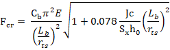
![]() = = elastic section modulus
= = elastic section modulus
![]() = distance between the flange centroids
= distance between the flange centroids


· FLB (noncompact flanges):
![]()
· FLB (slender flanges):
![]()
![]()
Shape: I-shaped members bent about their
major axis with noncompact web. ![]()
Limit state:
· Yielding:
![]()
![]()
![]() = elastic section modulus referred to compression flange
= elastic section modulus referred to compression flange
![]() = web plastification factor, determined in accordance with Section
F4.2(c)(6)
= web plastification factor, determined in accordance with Section
F4.2(c)(6)
· LTB (Lp<Lb<=Lr):
![]()
· LTB (Lb>Lr):
![]()
![]() = Value introduced
by user in member properties
= Value introduced
by user in member properties
![]() = Critical stress
= Critical stress

![]() = web plastification factor
= web plastification factor
· FLB (noncompact flanges):
![]()
· FLB (slender flanges):
![]()
![]()
Shape: I-shaped members bent about their
major axis with slender web. ![]()
Limit state:
· Yielding:
![]()
![]()
![]() = elastic section modulus referred to compression flange
= elastic section modulus referred to compression flange
![]() = Bending strength reduction factor (F5-6)
= Bending strength reduction factor (F5-6)
· LTB (Lp<Lb<=Lr):
![]()
· LTB (Lb>Lr):
![]()
![]() = Value introduced
by user in member properties
= Value introduced
by user in member properties
![]() = Critical stress
= Critical stress

![]() = Bending strength reduction factor (F5-6)
= Bending strength reduction factor (F5-6)
· FLB (noncompact flanges):

· FLB (slender flanges):
![]()
![]()
Shape: I-shaped members and channels
bent about their minor axis. ![]()
![]()
Limit state:
· Yielding:
![]()
· FLB (noncompact flanges):
![]()
· FLB (slender flanges):
![]()
Shape: Box. ![]()
Limit state:
· Yielding:
![]()
· LTB (Lp<Lb<=Lr):
![]()
· LTB (Lb>Lr):


· FLB (noncompact flanges):

· FLB (slender flanges):
![]()
![]() = effective section modulus determined with the effective width, be,
of the compression flange (F7-4 o F7-5)
= effective section modulus determined with the effective width, be,
of the compression flange (F7-4 o F7-5)
· WLB (noncompact web):

· WLB (slender web): Value is taken as the lowest for compression flange yielding (F7-7) and compression flange local buckling (F7-8)
![]()
![]() = elastic section modulus referred to compression flange
= elastic section modulus referred to compression flange
![]() = Bending strength reduction factor (F5-6)
= Bending strength reduction factor (F5-6)
![]()
![]()
Shape: Tubular![]()
Limit state:
· Yielding:
![]()
· FLB (noncompact):
![]()
· FLB (slender):
![]()
Shape:Tees
loaded in the plane of symmetry![]()
Limit State:
· Yielding (tee stems in tension):
![]()
· Yielding (tee stem in compression):
![]()
· LTB (Lp<Lb<=Lr):
![]()
· LTB (Lb>Lr):
![]()
![]()
![]()
(positive sign if the stem is under tension, negative if it is under compression)
The design shear strength, ![]() , and the allowable
shear strength,
, and the allowable
shear strength, ![]() , shall be determined
as follows:
, shall be determined
as follows:
For all provisions: ![]() = 0.90 (LRFD)
= 0.90 (LRFD) ![]() = 1.67 (ASD)
= 1.67 (ASD)
Except for webs of
rolled I-shaped members with ![]() .
.
In this case: ![]() = 1.00 (LRFD)
= 1.00 (LRFD) ![]() = 1.50 (ASD)
= 1.50 (ASD)
According to the limit states of shear
yielding and shear buckling, the nominal shear strength, ![]() , is calculated following the next considerations:
, is calculated following the next considerations:
Shape: I-shaped and Channels with shear
forcé in the web plane. ![]()
![]()
![]()
For
webs of rolled I-shaped members with![]() ->
-> ![]()
For all other I-shaped members and channels:
If ![]() ->
-> ![]()
If ![]() ->
-> 
It is assumed that there are no stiffeners;
therefore, the web plate buckling coefficient ![]() will be calculated
as a constant equal to 5.34.
will be calculated
as a constant equal to 5.34.
Shape: Tubular![]()
![]()
Because the Lv value (distance from maximum cutting force to zero) is unknown, Fcr is calculated as:
![]()
Shape: Other sections
![]()
![]() y
y![]() is calculated
following chapters G3,G4 y G6
is calculated
following chapters G3,G4 y G6
For this check, it is first necessary to
determine the value of Mn. This value comes into play in the checking of
formulas. The value of Mn, will be calculated in the same way as members
subjected to flexure; thus, the nominal flexure strength (![]() ) is the minimum of
four checks:
) is the minimum of
four checks:
1- Yielding
2- Lateral-torsional buckling
3- Flange local buckling
4- Web local buckling
In the case of having bending plus tension or bending plus compression, the interaction between flexure and axial force is limited by the following equations:
(a) For ![]()
![]() (H1-1a)
(H1-1a)
(b) For ![]()
![]() (H1-1b)
(H1-1b)
If the axial force is tension:
|
|
Required tensile strength (N). |
|
|
Available tensile strength (N):
|
|
|
Required flexural strength (N·mm). |
|
|
Available flexural strength (N·mm): Design: Allowable: |
|
y |
Strong axis bending. |
|
z |
Weak axis bending. |
|
|
Resistance factor for tension (Sect.D2) |
|
|
Resistance factor for flexure = 0.90 |
|
|
Safety factor for tension (Sect D2) |
|
|
Safety factor for flexure = 1.67 |
If the axial force is compression:
|
|
Required compressive strength (N). |
|
|
Available compressive strength (N): Design: Allowable: |
|
|
Required flexural strength (N·mm). |
|
|
Available flexural strength (N·mm): Design: Allowable: |
|
Y |
Strong axis of bending. |
|
Z |
Weak axis of bending. |
|
|
Resistance factor for compression =0.90 |
|
|
Resistance factor for flexure = 0.90 |
|
|
Safety factor for compression =1.67 |
|
|
Safety factor for flexure = 1.67 |
The following checks are carried out by CivilFEM:
If one of these checks do not meet the code requirements, it will not be possible to check the member under flexure plus tension / compression.


