Chapter 2 CIVILFEM ACT extension
Chapter 3 CIVILFEM ACT toolbar
Chapter 4 Details of CIVILFEM´s Window
4.1. Description of CivilFEM´s analysis settings
Chapter 5 Materials definition
5.1.3. Reinforcement steel material
5.2.1. Required properties for Eurocode 3
5.2.2. Required properties for Eurocode 2
5.2.3. Required properties for AISC 14th /15th Edition code
5.2.4. Required properties for ACI 318 code
5.2.5. Required properties for ACI 349-13 code
5.2.6. Required properties for GB50010 code
Chapter 6 Structural elements definition.
6.2. Steel beam structural element
6.2.1 Eurocode 3 steel beam properties
6.2.2 AISC steel beam properties
6.3. Concrete beam structural element
6.3.1 Eurocode 2 code properties
6.4. Beams cross section assignation
6.5.1 Definition of the shell properties
Chapter 8 Combination definition
8.2.2 Addition with Variable Coefficients
8.2.3 Incompatible or Exclusive Start States
8.2.7 Selection of Start States
8.2.8 Selection of Start States with Variable Coefficients
9.1. Selecting a new check or design
9.2. Interaction diagram Window
Welcome to the Theory Manual for CivilFEM ACT. This manual pretends to detail the information about the post-processing that is, the different types of checks and designs and the relationship between the input data and the results given by CivilFEM ACT.
This manual is essential for understanding how the program calculates results as well as how to interpret the results correctly. In other instance, theoretical basis of the check and design algorithms will be included.
With knowledge of the underlying theory, the user can perform analyses efficiently and confidently on CivilFEM ACT by using our full pack of capabilities.
Reading the whole manual will not be necessary; it is recommended to read only the paragraphs containing the specific algorithms being utilized.
· ANSYS. Software Help Documentation
In first, to make use of this post-processing utility, it becomes necessary to activate the CivilFEM ACT extension in order to show the toolbar on the ANSYS mechanical workspace.
This option is possible to be activated on the main task toolbar, from Workbench workspace, just in the “Extensions” panel. CivilFEM ACT extension can be activated either when the user already starts a new model or just in the moment the check or design process would be required.
When CivilFEM ACT extension is loaded please make sure that ANSYS Mechanical is closed.
The next scheme pretends to make the clearer as possible how to come out the CivilFEM ACT extension:

Once this first step has been fulfilled, the Toolbox of ANSYS Workbench will have a new option:

CivilFEM ACT toolbar is completely integrated on the ANSYS Mechanical interface:

The bar has been divided into three parts, consisting on: materials, cross sections or slabs definition and checking and designing.
1. Materials:

2. Cross sections and slabs definitions:

3. Checking and designing:

In another instance, it is remarkable that another button is located on the left side of the bar. This button allows the user to draw out the CivilFEM ACT´s containers and main properties that are needed for the post-processing.
![]()
The post-processing menu will be located inside the body of the project, following the ANSYS Workbench working model. This post-processing menu will contain all the information about the materials and cross sections or even slabs.


Analysis settings property deals with the choice of the code so as to check among the configuration to apply on the inner calculations. Those new parameters belonging to the window will be analyzed hereunder:
- Steel Codes: Depending on the user license the available codes are:
o Eurocode 3 (EN 1993-1-1:2005)
o AISC 14th Edition
o AISC 15th Edition
- Reinforced concrete Codes: Depending on the user license the available codes are:
o Eurocode 2 (EN 1992-1-1:2004/AC:2008)
o ACI 318 2014
o ACI 318 2019
o ACI 349-13
o GB50010-10
- Configuration parameters are related to the definition of the concrete interaction diagram:
o NED: number of steps on strains.
o WMIN: minimum reinforcement factor.
o DELTA: diagram center coefficient.
o NTD: number of steps on angles.
o WXMAX: maximum reinforcement factor.
o LIMCOUNT: maximum number of iterations on design.
o N2D: number of steps on 2D analysis.
o NMAXDIAG: maximum number of diagrams stored in file.
- By last, on the material´s settings section, the user will be able to define the active time, being 28 days by default. Material activation time and this property will affect to the inner properties of concrete materials, providing the appropriate values for the time dependent properties.
Material Age = Active time – Activation time
The materials parameters for Check and Design analysis must be introduced with the CivilFEM Materials Library.
Available choices could be: steel, concrete and steel reinforcement materials. Beneath this piece of introduction, the user can find an easy going guide with target to visualize the whole possible sort of materials.
The CivilFEM materials include code properties necessary for the checking and design of structures. These materials will be used for the post processing regardless of the material used in the ANSYS analysis.
Steel materials have been taken directly from the codes. In order to select a new steel material, click on the steel material button. The new material window will be displayed, being possible to pick out whatever steel option.

When selecting on a specific option, this will be marked on blue color. Now click on the Add button. After fulfilling this process, the material will appear inside the Material tree.

Next tables pretend to gather the sort of steel materials from the CivilFEM ACT library:
|
Eurocode 3 |
|
|
Fe 360 |
S460N/NL |
|
Fe 430 |
S275M/ML |
|
Fe 510 |
S355M/ML |
|
Fe E275 |
S420M/ML |
|
Fe E355 |
S460M/ML |
|
S 235 |
S 235 W |
|
S 355 |
S 355 W |
|
S 450 |
S 460 Q/QL |
|
S275N/NL |
S 235 H |
|
S355N/NL |
S 275 H |
|
S420N/NL |
S 355 H |
|
ASTM |
|
|
A36 |
A572Gr60 |
|
A529Gr42 |
A572Gr65 |
|
A529Gr50 |
A242 |
|
A441 |
A588 |
|
A572Gr42 |
A852 |
|
A572Gr50 |
A514 |
Concrete materials have been taken directly from the codes. In order to select a new concrete material, click on the concrete material button. The new material window will be displayed, being possible to pick out whatever concrete option.

When selecting on a specific option, this will be marked on blue color. Now click on the Add button. After fulfilling this process, the material will appear inside the Material tree.

Next tables pretend to gather the sort of concrete materials from the CivilFEM ACT library:
|
Eurocode 2 |
|
|
C12/15 |
C45/55 |
|
C16/20 |
C50/60 |
|
C20/25 |
C55/65 |
|
C25/30 |
C60/70 |
|
C30/37 |
C70/80 |
|
C35/45 |
C80/90 |
|
C40/50 |
C90/100 |
|
ACI |
|
|
fc_2500 |
fc_6000 |
|
fc_3000 |
fc_7000 |
|
fc_3500 |
fc_8000 |
|
fc_4000 |
fc_9000 |
|
fc_4500 |
fc_10000 |
|
fc_5000 |
|
|
GB50010 |
|
|
C15 |
C50 |
|
C20 |
C55 |
|
C25 |
C60 |
|
C30 |
C65 |
|
C35 |
C70 |
|
C40 |
C75 |
|
C45 |
C80 |
Steel reinforcement materials have been taken directly from the codes. In order to select a new steel reinforcement material, click on the steel reinforcement material button. The new material window will be displayed, being possible to pick out whatever steel option.

When selecting on a specific option, this will be marked on blue color. Now click on the Add button. After fulfilling this process, the material will appear inside the Material tree.

Next tables pretend to gather the sort of steel reinforcement materials from the CivilFEM ACT library:
|
Eurocode 2 |
|
S400 |
|
S500 |
|
ACI 318 |
|
ACI 318 2014 |
||
|
fy_60000 |
fy_70000 |
fy_80000 |
|
fy_65000 |
fy_75000
|
|
|
|
|
GB |
||
|
HPB235 |
HRB335 |
HRB400 |
RRB400 |
HRBF500 |
|
HPB300 |
HRBF335 |
HRBF400 |
HRB500 |
|
The material library includes many material options that represent most of the civil engineering construction materials.
Material properties considered by CivilFEM ACT include standard properties (Young Modulus, Poisson ratio, etc.) as well as other properties necessary for specific calculations, such as properties related to codes: characteristic strength, yield strength, reduction coefficient, etc.
CivilFEM ACT materials have five different kinds of properties:
· General properties: common properties for all kinds of materials.
· Material properties: reserved for steel, concrete, etc.
· Code properties: related to the selected code
· Active properties: obtained for the actual active time.
General properties are common to all categories of CivilFEM ACT materials and contain data identifying the materials (name, reference, type…); mechanical properties and the activation times of each material.
Specific material properties are always available for a particular material, regardless of the code under which the material was defined.
When defining a material inside CivilFEM ACT, standard properties are automatically assigned but the user can modify these properties at any given time. Additionally, there are several dependent parameters in a CivilFEM ACT material that are automatically updated. Therefore, the user should check these values when modifying the related properties.
For Eurocode 3 checking, the following steel material properties are used:
|
Description |
Property |
|
Steel yield strength |
Fy(th) |
|
Ultimate strength |
Fu(th) |
|
Partial safety factors |
gM0, gM1, gM2 |
These properties correspond to the steel materials detailed on the Eurocode 3(EN 1993-1-1:-2005).
For Eurocode 2 checking, the following concrete material properties are used:
|
Description |
Property |
Description |
Property |
|
Characteristic Compressive strength (28days) |
fck |
upper characteristic tensile strength |
Fctk0.95 |
|
Mean compressive strength (28days) |
fcm |
Strain of the peak compressive stress |
εc1 |
|
Design compressive strength (28days) |
fcd |
Ultimate strain in compression |
εcu |
|
Mean tensile strength |
fctm |
Coefficient dependent on the type of cement |
s |
|
Lower characteristic tensile strength |
Fctk0.05 |
Type of cement |
CeTp |
These properties correspond to the steel materials detailed on the Eurocode 2 (EN 1992-1-1:2004/AC: 2008).
For Eurocode 2 checking, the following reinforcing steel material properties are used:
|
Description |
Property |
|
Characteristic yield stress |
fyk |
|
Ultimate strength |
fyd |
|
Characteristic tensile stress |
ftk |
|
Characteristic elongation at maximum load |
εuk |
|
Steel safety factors |
gs |
These properties correspond to the steel materials detailed on the Eurocode 2 (EN 1992-1-1:2004/AC: 2008).
For AISC 14th /15th Edition checking, the following material properties are used:
|
Description |
Property |
|
Steel yield strength |
Fy(th) |
|
Ultimate strength |
Fu(th) |
|
Elasticity modulus |
E |
This code is divided into the ASD and the LRFD, being the same properties in both cases.
For ACI 318 checking, the following material properties are used:
|
Description |
Property |
Description |
Property |
|
Lightweight concrete modification factor |
λ |
Factor for rectangular stress distribution |
Β1 |
|
Specified compressive strength |
fc |
Type of curing |
CuTp |
|
Constant dependent on cement and curing |
β |
Type of cement |
CeTp |
|
Constant dependent on cement and curing |
a |
|
|
For ACI 318 checking, the following reinforcing steel material properties are used:
|
Description |
Property |
|
Specific yield stress |
Fy |
|
Design strength |
fyd |
For ACI 349-13 checking, the following concrete material properties are used:
|
Description |
Property |
Description |
Property |
|
Lightweight concrete modification factor |
λ |
Factor for rectangular stress distribution |
Β1 |
|
Specified compressive strength |
fc |
Type of curing |
CuTp |
|
Constant dependent on cement and curing |
β |
Type of cement |
CeTp |
|
Constant dependent on cement and curing |
a |
|
|
For ACI 349-13 checking, the following reinforcing steel material properties are used:
|
Description |
Property |
|
Specific yield stress |
Fy |
|
Design strength |
fyd |
For GB50010 checking, the following concrete material properties are used:
|
fcuk |
Specified concrete compressive strength at 28 days Art 4.1.1 (+Compression). fcu ≥ 0 |
||||||||||||||||||||||
|
ALPC1 |
Prism strength and cube strength ratio.
These values are obtained from the following formula: ALPC1=0.76 + 0.06*(fcuk - 50.0)/30.0 (- Compression) 0.76 ≤ ALPc1 ≤ 0.821 |
||||||||||||||||||||||
|
ALPC2 |
Brittle reduction coefficient.
These values are obtained from the following formula: ALPC2=1 - 0.13*(fcuk - 40.0)/40.0 (- Compression) 0.87 ≤ ALPc2 ≤ 1 |
||||||||||||||||||||||
|
DELTA |
Variation coefficient (Table 4.1.3).
|
||||||||||||||||||||||
|
FCK |
Standard axial compressive strength. fck=0.88*ALPc1*ALPc2*fcuk |
||||||||||||||||||||||
|
FC |
Design value for axial compressive strength (Art. 4.1.3) (+Compression fck≥0).
|
||||||||||||||||||||||
|
FTK |
Standard tensile strength (Art. 4.1.4) (+Tension ftk>0). ftk =0.88*0.395*(fcuk**0.55)*(1-1.645*delta)**0.45*ALPc2 |
||||||||||||||||||||||
|
FT |
Design value for tensile strength (Art. 2.1.3) (+Compression ft>0): fcd = ftk/GAMc |
||||||||||||||||||||||
|
S |
Coefficient which depends on the type of cement (0<s<1):
|
||||||||||||||||||||||
|
n |
Exponent of the stress strain diagram Art. 7.1.2-3. n=2-(fcuk-50)/60 [MPa] |
||||||||||||||||||||||
|
EPS0 |
Compressive strain at Fc Art. 7.1.2-4: EPS0 = 0.002+0.5*(fcuk-50)*10E-5 [MPa] |
||||||||||||||||||||||
|
EPSCu |
Limit compressive strain in concrete in Art. 7.1.2-5: EPScu = 0.0033-(fcuk-50)*10E-5 [MPa] |
||||||||||||||||||||||
|
CeTp |
Type of cement
|
For GB50010 checking, the following reinforcing steel material properties are used:
|
fyk |
Characteristic yield strength; fyk ≥ 0 |
|
|
fy |
Yield strength. (+ Tension) fy = fyk/GAMs |
|
|
fstk |
Characteristic tensile strength |
|
|
EPSmax |
Characteristic elongation at maximum load |
|
|
GAMs |
Safety factor for steel GAMs ≥ 1 |
|
These material properties may be accessible by interface. In case the user would need to modify these properties, the access will be possible from the “Modify” button, appearing when clicking on the material, with the right button of the mouse.

Once the material window has been displayed, the user will see that the information has been divided into four different tabs:
1. General.
2. Design Diagram.
3. Type of material.
4. Code.
General tab shows is the first of them. On it, all the general material information will be visualized. This tab shows the data classifying them into: general properties, type, time and mechanical properties.
For instance, hereunder you will find two material examples window, from Eurocode code. The Fe360 and the C25/30 material. Material tabs are similar but the Design diagram one, along with the activation time box.

General properties section will contain the name of the material. This name has been selected from a material list, which is easy accessible by expanding the reference drop down.
On another instance, it will be also possible to change the material into this list, updating all the current data to the belongings of this new material.
Type section displays the material type the user has selected, being “Steel” or “Concrete” depending on the model design.
Time section shows both the activation and the deactivation time.
Mechanical properties section visualizes the material Young modulus. This property will be mandatory for checking and designing.
Data belonging to specific materials, just like the Young Modulus, or even the code properties, are not submitted to change. Nevertheless, there is the possibility of defining the material as a “User defined” material.
This option will be available on the General tab, changing the reference from the designed material into the option “User Def”, on the top of the material list. Now, it is remarkable how material properties, not only from the General tab but also on the Type of material and on the Code tabs, would be accessible for any change.
The next tab is called Design Diagram, being only available both in concrete and steel reinforced material. On the contrary of the previous tab, this one will visualize different data if the selected material type is either steel or concrete.
Material behavior may be defined by user depending on the selected type option, being the default options: paraboloid rectangular on concrete material but also bilinear on the reinforced material.

However, the user could modify or even create a design diagram depending on the purpose. For this purpose, it will be necessary to change the type option from the default option into User-Defined.
Regarding concrete materials, diagram type has been defined as a parabolic-rectangular, by default. However, the user could modify or even create a stress- strain diagram depending on circumstances. For this purpose, it will be necessary to change the type option from parabolic-rectangular into User-Defined.
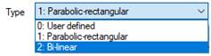
Now, the user will be able to add or delete any point from the Stress-Strain diagram.
Nonetheless, if the model requires a different diagram from the stress-strain, a Bi-linear diagram is also accessible.

On the other hand, depending on the current Plot type option, on the scheme will be visualized the tensioned, compressed or both parts at a time. This only affects to visualization but the calculation.
By last, in a concrete material Design Diagram tab, the Concrete age bar shows the different stress-strain curves depending on the specified day.
Otherwise, reinforcement steel design diagrams follow the approach of a steel material type. However, there is the possibility of choosing between two hypotheses:
1. Bilinear with horizontal top branch.
2. Bilinear with inclined top branch.

In the first one, strains are smaller for bigger stresses, than in a steel material stress-strain diagram, reaching a maximum stress even though strains continue growing.
The second hypotheses sustains that both compressed and tensioned branches are in a slightly slope, growing stresses along with strains.
Reinforced steel material diagram type has been defined as a bilinear with horizontal top branch, by default. On the other hand, as in concrete or steel materials, there is the possibility of selecting the User-Defined option.

Now, the user will be able to add or delete any point from the Stress-Strain diagram.
Plot type
option is as well modifiable so as to visualize the stress-strain diagram
branch. This may allow the user to read into the whole amount of data from the
stress-stain diagram.
Material tab name will change depending on the defined material type, along with the data contained on it.
For instance, in case of defining a steel material, the steel tab will contain information about the different thicknesses in order to apply while checking.

These thicknesses will be determined by code, being applied to every steel material from CivilFEM´s ACT library.
It is remarkable that some of the previous properties appear as non-writeable properties. That is because are specific properties from the code. If it becomes mandatory to change these parameters, the material would need to be changed to the “User Def” option, on the general tab, in the Reference material list. Now, those properties will be accessible to changes.
![]()
Now thickness or even a change in the Elastic Modulus would be available.

On another hand, if the shaped material would be concrete material, inner sections would change into the specified ahead:
· Time table for time dependent properties
· Properties used for structural linear analysis
· Strain limits used for section design

On time table for time dependent properties, time properties are fulfilled. Furthermore, options like adding, deleting or modifying and age may be available.
The next section stablishes some concrete properties used for structural linear analysis, just as the modulus type of the concrete.
The strain limits used for section design are specified beneath the previous section.
Just as in steel materials, if it becomes necessary to modify any of the defined properties previously detailed, the user will have to change the material Reference option from the material into the “User Def” option. This can be carried out in the general tab, inside the general properties.
To conclude, the reinforcing steel material properties are also specified, even though it is only one, based on the maximum strain allowed in tension at any point in the whole section.

This property is submitted to changes depending on checking requirements.
As in the Material tab, this one will be also submitted to change depending on the code selection. The name of the tab will be the same of the name of the checking code.
This tab use to contain coefficients belonging to partial factors or mechanical properties, both necessary in the post-processing check or design. Nevertheless, those properties will vary depending on the code.
Please, review chapter 5.2 to see the required material properties depending on the code.
A structural element is defined as every part visibly differenced, but linked, on which a structure could be divided into.
Structural elements define the part of the model that will be check or design by CivilFEM extension.
It is essential not to confuse structural element with finite element. The former is the structural entity about to be meshed and the latter is actual mesh discretization of the structural entity. Following figure shows the difference between structural and finite element:

In the figure above a single shell structural element (slab) generates 32 finite elements (4-node shells) and each beam structural element (column) generates 7 finite linear elements (2-node beams).
To attach the ANSYS model parts to CivilFEM´s structural elements user can make a selection of geometries or mesh elements.
CivilFEM ACT supports, on the checking post-processing, carrying out two different types of structural elements:
· Beams (steel or concrete)
· Shells
As previously detailed, if the user would like to perform a structural element entity, it becomes necessary to make use of the structural element panel belonging to the CivilFEM´s ACT toolbar. This panel is located on the middle part of the mentioned toolbar.
When creating either steel or concrete structural element, a new item appears on the CivilFEM ACT post-processing menu, inside the structural elements group.


When performing a beam structural element, besides being added to the CivilFEM ACT menu, a new window comes out on the CivilFEM´s details window, on the left bottom side. This window has been divided into three sections:
· Material definition
· Geometry or mesh assignation
· Steel code properties / Reinforced concrete code properties.
A beam structural element, no matter if steel or concrete, will always need to assign both geometry and material entities. However, the code properties will be different, due to be not only dependent on the material but also the code to check.
The code properties will appear in the Details Window.
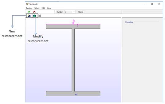
Steel beams are directly linked to a cross section, which contains all the data belonging to the mechanical and code properties from this section.
This section is accessible by clicking on the steel beam structural element with the right button of the mouse, choosing the Modify option.

Thus, the window belonging to the section appears on Workbench interface. If the user would require making any change on the section data, this can be carried out on this window.

For example, in the image above, a IPE 300 steel beam profile has been performed. This window displays the plot of the section along with the section properties. Those properties are viewable but writeable.
If necessary to modify any data belonging to the section, this will be carried out on the Edit panel, on the top part of this window. Edit panel is shaped by a group of options whose functions are related to provide the correct definition to the section.

General properties option shows some basic information related to the section, such as: the section reference, its name and the type:

The next section consists of the definition of every type of visualization: Tessellum, Faces, Reinforcement Groups and Plates. Editing either by faces or by reinforcement groups does not make sense in a steel beam section due to be related with the concrete reinforcement.
When editing by tessellate, the model view plots the section divided into tessellas.

Moreover, it is remarkable that, there is the possibility of changing the type of material of any tessella by assigning a different material. This can be carried out by using the Changing material type button.
In case the edit made up by steel plates, the profile of the beam will be divided into a group of plates, which are available for any change depending on the structure requirements.
Furthermore, when selecting any of the plates, their properties will be specified on the right space of the window, into a window so call Dimensions. The specified properties will be:
· Number of the plate.
· Material number.
· Type of plate depending on the effective axis.
· If the plate is free or fixed connected on their extremes.
· Geometrical properties such as: thickness and starting and ending points (yp1, yp2, zp1, zp2).

There are two methods in order to modify the structure of the plates. One of them consists of creating new plates from the starting step. That is, clicking on the new plate button and entering the specific data.
When creating or modifying a plate, the plate properties window is displayed:

This window gathers the necessary properties in order to shape the plate. It becomes mandatory to specify the type of plate depending on the bending moment application, besides the condition on the plate extremes.
The plate type for bending moment assigns the behavior of the plate depending on the effective axis. On another hand, the union condition specifies the condition for both of the extremes of the plate. That is, this specifies if the plate is fixed to other plate or, by contrary, the plate is not connected to any other plate.
Thus, once these previous properties have been assigned, it will be necessary to determine the thickness of the plate along with the plate starting and the ending coordinates.
On the other hand, there is another possibility when entering plates. There is also possible to enter them by commands.

The entered command has to follow the Command description specified in the window. In case of specifying the commands ahead, plates dimensions would be equal to a IPE 300 section will be shaped:
§ PLT, 1, 1, 2, 1, 0,1.07e-002, 0,0.14465,-7.5e-002,0.14465
§ PLT, 2, 1, 2, 1, 0, 1.07e-002, 0 ,0.14465, 7.5e-002 ,0.14465
§ PLT, 3, 1, 2, 1, 1,7.1e-003,0, 0.1393, 0,-0.1393
§ PLT, 4, 1, 2, 1, 0,1.07e-002, 0,-0.14465,-7.5e-002,-0.14465
§ PLT, 5, 1, 2, 1, 0,1.07e-002, 0,-0.14465, 7.5e-002,-0.14465
Key parameter defines the operation in order to carry out. That is:
§ NEW: starting the selection
§ PLT: define or modify plate
§ DEL: delete plate
IPLT parameter is related with the plate number in order to define or delete.
PTY: type of plate for My bending moment (0: Undefined; 1: Flange; 2: Web).
PTY: type of plate for Mz bending moment (0: Undefined; 1: Flange; 2: Web).
CP1 and CP2: conditions on extremes (0: Free; 1: Fixed).
THCK: thickness of the plate.
YP1 and YP2: Y coordinates of point 1 and point 2.
ZP1 and ZP2: Z coordinates of point 1 and point 2.
Beside this previous information, the Edit panel shows all that information related with the mechanical and code properties.
Mechanical properties option visualizes the geometrical section properties, whether if the profile has been shaped by library or by plates (generic one). In this example, the mechanical properties of a IPE 300 section, will be showed:

These properties are perfectly writeable so, they are available for any change if necessary.
The code properties definition depends on the code used in the check post-processing.

By last, to conclude with the steel beams cross sections, there is the possibility of importing a specific section from CivilFEM´s ACT library. This will be available on the edit panel, when choosing the Import Section option.

This option allows the user to access to the library of CivilFEM ACT.

This library is quite extensive, so if there is a specific required section type, the find tool can be a good searching tool.

This tool executes the search process depending on the property and min and max values assigned to that search.
On the other hand, the user will be allowed to enter a new shape by using the Add shape tool. When clicking on this tool, this window is displayed:

Thus, the user can decide in which section type the new assigned section will be added.
For instance, a new I Double T profile will be entered in the I-Beams group. Profile characteristics will be specified ahead:

After introducing all measures, another window appears. This window contains a panel with the mechanical properties, another one with the coordinates and, by last, a miscellanies panel.

After this process, the user´s shape is stored into the CivilFEM´s ACT library. To be more specific, inside the User classification profiles.

Now, the cross section of the steel beam will be shaped by plates.
Once the Edit panel has been properly detailed, we will focus the explanation above the View panel.
View panel shows all the information belonging to the visualization of the section.

Boundary option is stablished by default; nevertheless, all other visualization options may be displayed.

Visualization by points on the top left space, visualization by tesella on the top right space, visualization by plates on the bottom left space and visualization by boundary on the bottom right space. Visualization by reinforcement or by faces does not make any sense in a steel beam as previously detailed on the Edit panel explanation.
In addition, inside the view panel, there is the possibility of showing some other parameters belonging to these previous types of visualization. This may be managed inside the Options menu.

As seen in the image below, all types of visualization are on the left side and visualization criteria next to them. The criteria allow the user to specify the visualization parameters:
|
Criteria |
Default |
|
Item Index |
|
|
Material Number |
|
|
Material Type |
Thus, once a criteria has been attached to any of the visualization modes, when selecting that specific visualization type, on the View panel, the section window will come out the section plotting showing the assigned criteria.
Code properties related with the Eurocode 3 are visualized in the next image:

Auto option takes the length from the geometry selected. User also can select manual input for the member length
Code
properties related with the AISC are visualized in the next image: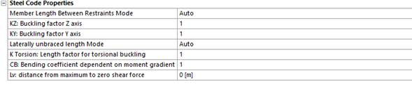
Auto option takes the length from the geometry selected. User also can select manual input for the member length
As in a steel beam, concrete beams are directly linked to a cross section, which contains all the data belonging to the mechanical and code properties from this section.
This section will be also accessible by clicking on the concrete beam structural element with the right button of the mouse, choosing the Modify option.

Thus, the window belonging to the section appears on Workbench interface. If the user would require making any change on the section data, this can be carried out on this window.

For example, in the image above, a double T concrete beam profile has been performed. This window displays the plot of the section along with the section properties. Those properties are viewable but writeable.
If necessary to modify any data belonging to the section, this will be carried out on the Edit panel, on the top part of this window. Edit panel is shaped by a group of options whose functions are related to provide the correct definition to the section.

General properties option shows some basic information related to the section, such as: the section reference, its name and the type:

The next section consists of the definition of every type of visualization: Tessellum, Faces, Reinforcement Groups and Plates. Visualizing by plates does not make sense in a concrete beam section due to be related with steel sections.
When editing by tessellate, the model view plots the section divided into tessellas.

Moreover, it is remarkable that, there is the possibility of changing the type of material of any tessella by assigning a different material. This can be carried out by using the Changing material type button.
Due to the fact of being concrete profiles, there is the possibility of reinforcing the section. This can be made up in the Reinforcement Groups editing option.
When defining a new reinforcement, some parameters such as: material, geometrical cover, reinforcement faces and reinforcement amount has to be entered. All these parameters will be assigned in the window ahead:

Therefore, the first step will be to assign a reinforcement material. This material is necessary to has been made up by means of the Create Reinf Steel Material button, in the CivilFEM ACT toolbar bar.
As seen in the reinforcement properties window, a S500 steel reinforcement material has been carried out.
For instance, a practical example with the characteristics ahead:
· S500 steel reinforcement.
· Mechanical cover of 0.01 m.
· 6Φ12 reinforcement distribution.
· Reinforcement in Face 2.
· End option: Bars at both ends at MC.
Setting a 6Φ12 reinforcement distribution implies to use the option By Number of bars, due to activate the required fields.

The reinforcement will be plotted along with the section´s profile in the main space of the window.

Reinforcement group’s definition depends on the type of check or design in order to execute. That is, bending reinforcements will be carried out in case of executing a check or design closely related with structures submitted to bending moments.
The same situation is stablished in case of having shear or torsional forces due to be mandatory the reinforcement for these purposes. This will be carried out on the Shear and Torsion tabs from the Reinforcement properties panel.

Amount options can be managed depending on the reinforcement preferences.

Related with the reinforcement editing, editing by faces allows the user to stablish a new reinforcement face by entering a new face by points.

As it is noticeable, the sections have some reinforcement faces by default. Regarding the I Double T profile, there are two reinforcement faces, one in the top and the other one in the bottom.
However, as previously said, the user can enter a new reinforcement face by using the New face by Points tool. When entering a new face, first of all, CivilFEM demand you to introduce a number for the new face.
The next example is very illustrative due to the fact that a new face reinforcement with the number 3, has been entered. This face is shaped by joining two points, which belongs to the section, with the mouse.
As a result of this, the face has been stablished in the web of the I Double T section. The face number three is that colored in yellow.

On the other hand, if any change is required in any of the faces, when clicking on the face to modify, some new options become active on the menu.

Now this new face is perfectly available to be assigned on the reinforcement group panel. In order to visualize this, a new reinforcement will be shaped among the one created on the reinforcement group example. Reinforcement group will have the next characteristics:
· S500 steel reinforcement.
· Mechanical cover of 0.001 m.
· 1e-3 m2 amount of reinforcement
· Reinforcement in Face 3.

Beside this previous information, the Edit panel shows all that information related with the mechanical and code properties.
Mechanical properties option visualizes the geometrical section properties, whether if the profile has been shaped by library or by plates (generic one). The next image shows the mechanical properties of a concrete section, based on the I double T example.

These properties are perfectly writeable so, they are available for any change if necessary.
On the other hand, the code properties definition depends on the code used in the check post-processing.
Once the Edit panel has been properly detailed, we will focus the explanation above the View panel.
As previously said in the steel section, the view panel shows all the information belonging to the visualization of the section.

Boundary option is stablished by default; nevertheless, all other visualization options may be displayed.

Visualization by points on the top left space, visualization by tesella on the top right space, visualization by faces on the bottom left space and visualization by reinforcement groups on the bottom right space. Visualization by plates or by faces does not make any sense in a concrete beam as previously detailed on the Edit panel explanation.
In addition, inside the view panel, there is the possibility of showing some other parameters belonging to these previous types of visualization. This may be managed inside the Options menu.

As seen in the image below, all types of visualization are on the left side and visualization criteria next to them. The criteria allow the user to specify the visualization parameters:
|
Criteria |
Default |
|
Item Index |
|
|
Material Number |
|
|
Material Type |
Thus, once a criteria has been attached to any of the visualization modes, when selecting that specific visualization type, on the View panel, the section window will come out the section plotting showing the assigned criteria.
Also code properties can be edited. This properties depends on the code selected.
Code properties related with the Eurocode 2 are visualized in the next image:

For further explanation of the parameters, check the table:
|
Property |
Description |
Property |
Description |
|
REC |
Reinforcement cover for code properties calculation |
Theta |
Angle of concrete compressive struts |
|
BwVy / BwVz |
Minimum width in depth for Vy and Vz |
RHO1 |
Ratio of longitudinal tension reinforcement |
|
DY / DZ |
Y and Z effective depth |
Key AST |
Situation of torsional reinforcement |
|
T |
Equivalent wall thickness |
PHI |
Bars diameter |
|
AK |
Area enclosed by the center line of thin wall |
RHO |
Effective reinforcement ratio |
|
UK |
Perimeter of AK Area |
C |
Geometrical cover |
Code properties related with the ACI 318 are visualized in the next image:

For further explanation of the parameters, check the table:
|
Property |
Description |
Property |
Description |
|
F. Bending |
Inelastic energy absorption factor for bending |
AO |
Gross area enclosed by the flux of tangential stresses |
|
REC |
Reinforcement cover for code properties calculation |
PCP |
External perimeter of concrete section |
|
BwVy / BwVz |
Minimum width in depth for Vy and Vz |
PH |
Perimeter of closed-stirrups |
|
DY / DZ |
Y and Z effective depth |
TKmin |
Minimum wall thickness |
|
ACP |
Area enclosed by the external perimeter of the section |
CC |
Geometrical cover |
|
AOH |
Area enclosed by the closed-stirrups |
|
|
Also the ACI 318 code demands the user to enter the Strain reduction factor, also so called: Phi.

If the user introduce a value then this constant value will be used for all the points. Default value of 0, will allow the CivilFEM to calculate it according the code.
Code properties related with the GB50010 are visualized in the next image:

Also the GB50010 Code demands the user to introduce a few member properties:

CivilFEM ACT works in a different way depending on if the beam has been made out of either concrete or steel. This is because the cross section of a steel beam needs the definition of the plates which shape the profile.
Depending on the type of cross section defined in ANSYS, CivilFEM can extract the plate section information and create the CivilFEM cross section. This can be achieved if the cross section is defined as a known ANSYS section type (I section, T section, Channel section, box section, L section or rectangular/circular tube section).
If the ANSYS cross section type can´t be evaluated by CivilFEM a warning appears:

This warning comes out in the moment after the user assigns the geometry to the steel beam. This means that it is mandatory to create the plates of the steel cross section. This can be achieved by three different methods:
2. Importing a section from the CivilFEM ACT´s library.
3. Importing a user profile from the CivilFEM ACT´s library.
The process of shaping the plates has been widely explained on their specific sections. So as to access to that information, click on the previous links.
Once the plates of the cross section have been properly created, the steel beam will be completely functional for calculations.
In regard to a concrete beam, there is not any problem when assigning the geometry. That is, a concrete beam does not need plates in its calculations due to this property only becomes necessary to the steel beams.
Thus, the concrete beam is completely functional from the moment the user assigns the geometry. However, concrete beams need to be reinforced. Reinforcement process has been widely detailed inside the Concrete cross sections. For further information about reinforced concrete beams, click on the link.
Shell structural element is carried out by using the create shell tool from the CivilFEM´s ACT bar. It is important to add that shell structural elements will be only available for concrete material.
The difference in the establishment process between concrete beams and shells is that when the user carries out the shell structural element, CivilFEM ACT asks directly about the material to assign along with the information of the different types of reinforcement:
· Bending reinforcement
· Shear reinforcement
· In plane shear reinforcement


In the first step, only entering the information about the material is required. The data about the reinforcements may be fulfilled later by modifying the shell structural element.
Once the shell establishment process has being finished, a new item appears on the CivilFEM ACT post-processing menu, inside the structural elements group.

After performing the shell structural element, if the user clicks on it with the left button of the mouse, a new window so called Details of “CF Concrete Shell” will come on the bottom left side. This window has been divided into two sections:
· Geometry assignation
· Reinforced concrete code properties.
The geometry assigned to the structural element can be multiple. That is, they would be more than one shell into the same structural element. Nevertheless, as a piece of advice, it is necessary to enter shell´s geometries with the same thickness, if it is not; CivilFEM ACT will take the lesser thickness of all those shell´s geometries. The shell thickness is automatically assigned to CF shell structural element from ANSYS properties, but can be edited by the user in the general shell properties.
All the properties required to carry out the check and design post-processing, will be provided on the Shell Vertex window.
Shell properties are those which are contained on the Shell Vertex window. These properties can be changed, depending the user preferences, by clicking on the concrete shell structural element with the right button of the mouse, choosing the Modify option.

So, in case of shaping a concrete shell 0.2 m thick, with a C35/45 concrete material, the shell general properties would remain in this appearance:

Bending Reinforcement parameters will be specified in the bending reinforcement tab, from the Shell Vertex window.

For further details about the bending parameters, check the table beneath:
|
Property |
Definition |
|
Reinf. Mat |
Reinforcement Material |
|
Mec. Cov. & MCXT, MCXB, MCYT and MCYB |
Mechanical cover |
|
ASSXT/ASSXB and ASSYT/ASSYB |
Ratio of the reinforcement area in X top, X bottom, Y top and Y bottom |
|
SXT/SXB and SYT/SYB |
Longitudinal spacing in X top, X bottom, Y top and Y bottom |
|
PHIXT/ PHIXB and PHIYT/ PHIYB |
Bars diameter in X top, X bottom, Y top and Y bottom |
Furthermore, it
is useful to add that parameters ASSXT/ASSXB and ASSYT/ASSYB
would be active in case of reinforcing by amount. Otherwise, the shell will be
reinforced by assigning a longitudinal spacing with its corresponding diameter
of bar.
On the other hand, depending on situation, the user can enter a different mechanical cover for X & Y (MCXT, MCYT) top and X & Y (MCXB, MCYB) bottom locations.
As in the bending reinforcement, the Shear Reinforcement parameters will be specified in the shear reinforcement tab, from the Shell Vertex window.
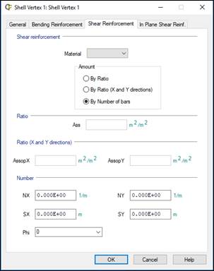
For further details about the bending parameters, check the table beneath:
|
Property |
Definition |
|
material |
Reinforcement Material |
|
Ass |
Reinforcement area |
|
AssopX/AssopY |
Out of plane of shear reinforcement in X and Y direction |
|
NX/NY |
Number of bars per unit length in X and Y direction |
|
SX/SY |
Longitudinal spacing between bars in X and Y direction |
|
Phi |
Diameter of bars |
Furthermore, it is useful to add that parameters Ass would be active in case of reinforcing by amount. Otherwise, the AssopX and AssopY parameters may take part in case of reinforce the section by amount in X and Y direction. By last, the SX, SY and Phi parameters would be required in case of reinforcing by number of bars.
By last there is only one method in order to reinforce the shell structural element. The In Plane Shear Reinforcement, specified in the in plane shear reinforcement tab from Shell Vertex window.

For further details about the bending parameters, check the table beneath:
|
Property |
Definition |
|
material |
Reinforcement Material |
|
AssipX/AssipY |
In Plane Shear Reinforcement in X and Y direction |
Once the user has fulfilled the necessary data, the checking process will take that information, entering in the calculation process. It becomes necessary to add that it is not needed to make use of the three different reinforcement tabs. It will be only necessary to make use of that tab whose data are relevant for checking.
Data Sets container contains the single load cases solved in ANSYS that will be used to combine.
Once the single load cases have been defined in ANSYS, use right click to fill the container with all load cases:
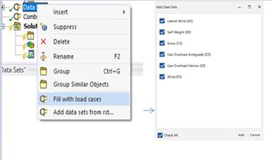
The option Add data sets from rst can be used to select the ANSYS result file manually
CivilFEM ACT will append the previous analysis into the Data Sets container:

User can select the result set of the ANSYS .rst file to combine. By default, the last set is used but can be specified by result set number if it is necessary:

With the combination explorer window, you can define and see the combinations in an easy way.
User can select the data sets previously defined to perform the combination. CivilFEM will combine the results in the structural elements defined by the user
CivilFEM ACT gives the choice of defining the combination whether by the user or by code.

Once one of these two options, user or code combination type, has been select, use the right click to explore the combination properties:

In case you define the User type combination the combination explorer window will be divided into three parts:
1. Start states for combination. Can be the data sets defined or previous combinations defined.
2. Combination rule. Define the combination rule that will be apply
3. Combination defined. Here user can review the combinations, edit the start states and modify the coefficients.

The type drop, in the square number 2 in the previous figure, has a wide range of combinations, whose rule definition can be checked below:
Addition [ADD]
Addition with Variable Coefficients [ADDVC]
Incompatible or Exclusive Start States [INCOMPAT]
Compatible Start States [COMPATIB]
Optional Start States [OPTION]
Opposed Start States [OPOSED]
Selection of Start States [SELECT]
Selection of Start States with variable coefficients [SELECTVC]
Every Start State is added with fixed coefficients. Each Start State is only multiplied by one coefficient. This rule uses classic addition, equivalent to the combinations with ANSYS.
Start States are added with variable coefficients. A maximum and minimum combination coefficient is assigned to each Start State. This rule can be used for combinations according to codes, for example, C = gfg · G + gfq · Q.
Either a maximum Start State is selected from the defined states or no state is selected. It is not necessary to define coefficients. This rule is used as a representation of mobile loads that can only be placed in only one position at a given time.
Any Start State subset can be added together (all, many, one, or none of them). Coefficients are not necessary. This rule is used to represent live loads that can occur simultaneously (surface loads).
Only one of the Start States is selected. Coefficients are not necessary. This rule is useful for selecting among different Start States. For example, different locations of a load on a pile, different code Start States, etc.
All the Start States of the combination are added, but each are multiplied by a maximum coefficient equal to +1 or a minimum coefficient equal to –1. This rule is useful for loads that act distinctly in two opposite directions (wind, earthquakes, etc.).
A fixed number of Start States, selected among the ones defined, is added. The number of Start States to be added is required input, not the coefficients. This rule is used for moveable loads that can act in more than one position.
A fixed number of Start States are added and each one of them can be multiplied by two coefficients. Input requirements are the two coefficients per Start State and the number of Start States to be added. This is the most general type, but with degeneration it adapts to any of the previous types as shown in the table below.
|
TYPE |
Coefficient |
Number of Start States to add |
|
|
Maximum |
Minimum |
||
|
ADD |
C1* |
C2 = C1 |
ALL |
|
ADDVC |
C1* |
C2* |
ALL |
|
INCOMPAT |
0 |
1 |
1 |
|
COMPATIB |
0 |
1 |
ALL |
|
OPTION |
1 |
1 |
1 |
|
OPOSED |
1 |
-1 |
ALL |
|
SELECT |
1 |
1 |
NADD* |
|
SELECTVC |
C1* |
C2* |
NADD* |
* This data should be introduced by the user.
On the other hand, if you define the by code type combination the combination explorer allows to create combination by code. The available code combinations are:
- Eurocode
- ASCE 7-05
- ASCE 7-10
In this case the combination explorer window will be divided into three parts:
1. Loads. This section allows the user to enter the loads to operate in the combinations but also assign the type of load.
2. Compatibilities. In this division the user may assign incompatibilities or concomitance between the different loads.
3. Combinations. This division make possible to change the combination options so that the user is able to obtain those necessary.
The Load section contains the options to add the different loads as well as assign the limit state definition or even the safety factor coefficients.

The Compatibilities window allows the user to determine the incompatibilities between the different loads, in case they are, or even the priority of these loads in the face of combining.

In the incompatibility section, the user will be able to determine if two or more loads cannot be combined by deactivating the check box:

Moreover, in the concomitance window, we can select the live load as dominant over the snow load:

Therefore, the live load will be higher factorized than the snow load on those combinations that both of them take part at the same time.
The Combination section contains the different options to modify the combination configurations in order that the user would obtain only those he require.

In this case the combination explorer window will be divided into two parts:
1. Loads. This section allows the user to enter the loads to operate in the combinations but also assign the type of load.
2. Combinations. This division make possible to change the combination options so that the user is able to obtain those necessary.
The Load section contains the options to add the different loads as well as assign the type of load.

The Combination section contains the different options to modify the combination configurations in order that the user would obtain only those he require.

When solution of CivilFEM´s Check and Design analysis is done, the combination defined is solved. The list of algebraic combination can be reviewed in the solve.out file:

Each of these combinations will be stored in the different steps. Thus, to change from one type to another, the user has to select the step option, in the result details window, in the “Definition” drop.
CivilFEM ACT can execute various types of checks or designs according to the implemented codes. These codes allow checking all the functional structural elements from CivilFEM, whether steel and concrete beams or concrete shells. Hereunder we find a little scheme of the available codes:
- Steel beam codes:
· Eurocode 3
· AISC 14th Edition
· AISC 15th Edition
- Shells and concrete beams:
· Eurocode 2
· ACI 318 2014
· ACI 318 2019
· ACI 349-13
· GB50010-2010
For further details of checking/design process, please refer to the ACT Reinforce Concrete manual or ACT Structural Steel manual.
Buttons from the CivilFEM ACT´s toolbar are differenced by the structural elements to check. That is, there are three differenced buttons whose purpose is to check whether steel beams or concrete beams or even concrete shells. This was further detailed on section 3.1. Toolbar´s description.
Whatever the type of check, once the user has made use of it by clicking on the last section of CivilFEM ACT´s toolbar, a new item will take place inside the Solution group, which belongs to the established load step.

Once the type of check has being displayed on the load step, the details of this check can be assigned on the Details window. This window distinguishes between five different bars, as seeing in the image below:
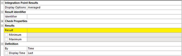
The Integration Point Results section determines the plotting results visualization. That is, each of the display option has an inner operation, providing the results according to this expression. Display options from Workbench will be:
· Averaged
· Elemental Mean
· Unaveraged
These resources may be defined as:
Averaged: averaged contours distribute the average elemental nodal results across element and geometric discontinuities.
Elemental Mean: Computes the elemental average from the averaged component results. Therefore, due to only taking the averaged results from all their components, the post-processing is carried out much faster.
Unaveraged: unaveraged contour results display as element nodal contours that vary discontinuously even across element boundaries. These contours are determined by linear interpolation within each element and are unaffected by surrounding elements.
The results identifier section is composed by the Identifier field. This property assigns a specific name to the check type. Target is to use these check results into a User result by assigning the check identifier in the Expression field from the User defined result.

Next section is one of the most important in the checking process due to be that on which the check properties are assigned. These properties will be used in calculations and will depend on the structural element to check along with the checking code. Code properties will be properly detailed on the chapter specified for this particular code.
Results section is shaped by the type of result and the Minimum and Maximum value of this result. In addition, if there is more than one type of result belonging to the same type of checking, the solving process will solve all of them at once.
By last, Definition options take part in the visualization of the results. That is, results´ definition can by expressed by:
· Time
· Result set
· Maximum over time
· Time of Maximum
· Minimum over time
· Time of Minimum
Despite the existence of these six different options, only the Time and Result set definitions will be functional in the checking process.
This implies that the user will manage to obtain a checking result in a specified time or even in a particular result set. This may be achieved by assigning the required time or result set on the Display time or Set Number field, respectively.
Definition by time:
![]()
Definition by Result Set:
![]()
For reinforced concrete beams and shells CivilFEM ACT allows the user to plot the axial-moment interaction diagram of the section. For further details of how the interaction diagram is created, please refer to the Reinforced Concrete Manual.
The interaction diagram setup window allows the user to select the input required

Settings:
Type: select between reinforced concrete beam or shell
Dirkey: element direction to plot
Max. stress in concrete: Activate and set a value if users requires to limit the stress in concrete
Max. stress in steel: Activate and set a value if users requires to limit the stress in reinforced steel
Forces and Moments:
Mode: select between obtained the values from the CivilFEM solution or introduced the values by the user.
Steps: Select the steps to check if Result file mode is activate
Axial force/bending moment: Values to check if User mode is selected
Apply to: Select the scope of the interaction diagram.
If result file mode is selected and the scope is the structural elements, the interaction diagram is calculated for all the elements and ends of the structural element. Then the result plotted indicate the worst case of all, but user can plot all de design forces and moments evaluated

