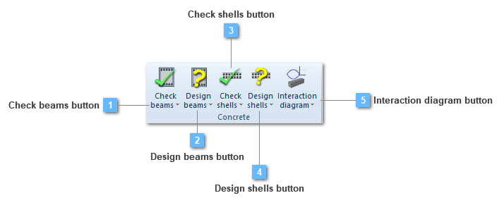
Interaction diagram button
Plot the interaction diagram
The interaction diagram is a curve in space that contains the forces and moments (axial load, bending moment) corresponding to the shell ultimate strength states. In CivilFEM the ultimate strength states are determined through the pivots diagram.
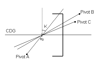
A pivot is a strain limit associated with a material and its position in the shell vertex. If the strain in a section pivot exceeds the limit for that pivot, the shell vertex is considered cracked. Thus, pivots establish the positions of the strain plane. So, in an ultimate strength state, the strain plane includes at least one pivot of the shell vertex.
In CivilFEM, pivots are defined as material properties and these properties (pivots) are extrapolated to all the points through the thickness of the shell vertex, accounting for the particular material of each point (concrete or reinforcement). Therefore, for the section strain plane determination, the following pivots and their corresponding material properties will be considered:
|
A Pivot
|
EPSmax. Maximum allowable strain in tension at any point of the shell vertex (the largest value of the maximum strains allowable for each point of the section in case different materials in the section exist).
|
|
B Pivot
|
EPSmin. Maximum allowable strain in compression at any point of the section (the largest value of the maximum strains allowable for each point of the section).
|
|
C Pivot
|
EPSint. Maximum allowable strain in compression at the innner points of the section.
|
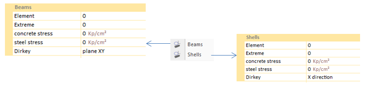
Beams & Shells
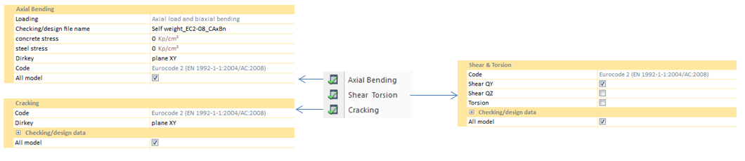
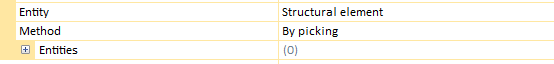
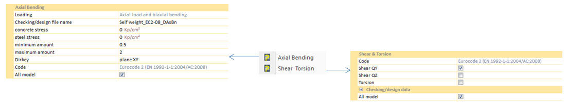
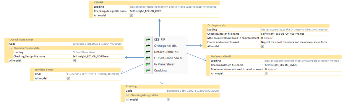
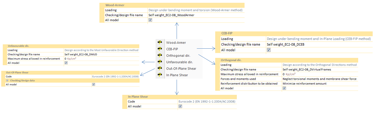
In order to design an interaction diagram, it is necessary to specify both an element and an extreme of the concrete body that will be analyzed. This criterium must be followed not only in beam diagrams but in shell ones also.
Concrete and steel stresses establish the maximum stresses for diagram creation. If no value is chosen, CivilFEM will take the default material values.
Dirkey option define in which plane, or direction, the concrete body is going to be analyzed.
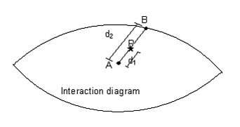
An example of a shell diagram: 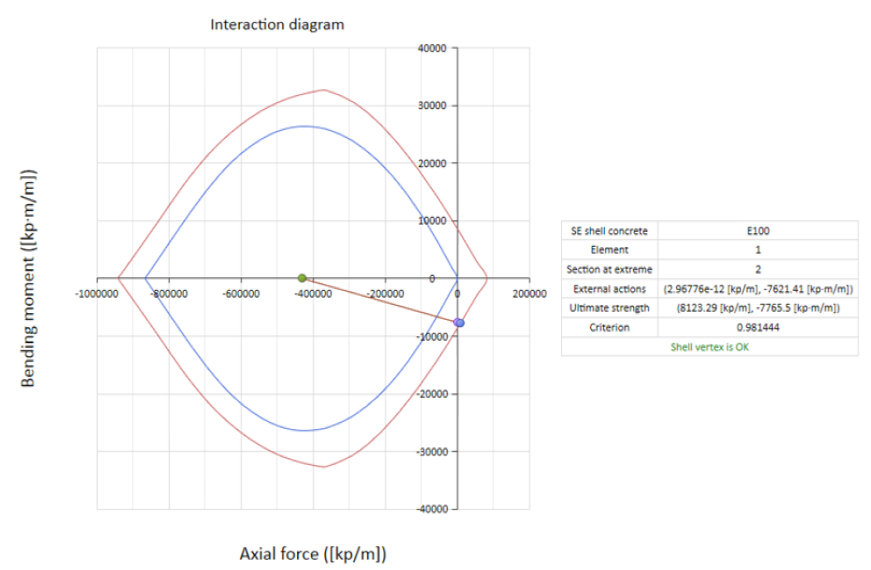
As shown in the diagram, the criterion is under 1, so the concrete shell withstands the working load.
Beams (Prestressed)
The procedure is similar to the previous interaction diagram defined but taken into account:
In the calculation of total prestressing steel strains, apart form the strain produced in the corresponding ultimate state deformation plane fiber, the prestressing strain and the decompression strain are also considered:
Where:
|
|
Concrete decompression strain at the considered reinforce level
|
|
|
Prestressing steel strain due to the prestressed action in the considered phase, considering the losses that have taken place.
|
The strain decompression calculation is carry out taking into account the initial prestressed on the effective section and the long term losses on the homogenize section.
To determine the strains plane (ultimate strength plane) of the section. εg and θ are used as independent variables. The process is composed of the following steps:
1. Pivots calculation for each the cross section points are based on the associated material, its position within the cross section and the prestressed in case of the prestressing steel.
2. From the total pivots number a deformation planes sweeping is made passing through some of the pivots (without going through any of them).
3. Each one of the strain planes (ultimate strength plane) correspond with a curvature and a strain in the section’s center of gravity and determine the deformation corresponding to each of the section points ε(y).
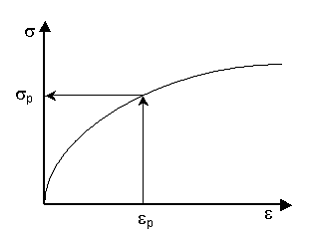
4. From the ε(y) strain and the prestressing steel pre-deformations, the stress corresponding to each point of the section (σp) is calculated entering in the material stress-strain diagram of each point. This way, the stress distribution inside the section is determined.
Stress determination in a point
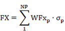
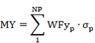
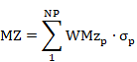
5. So, as the stress distribution is known, the corresponding ultimate forces and moments (Fu, Mu), are obtained by the summation of stresses on each one of the sections point multiplied by its corresponding weight according to the considered flexion axis.
Where:
|
NP
|
Number of points of the section.
|
|
WFX, WMY, WMZ
|
Weights of each section points.
|
The contribution of the prestressing steel is added to these forces and moments.
6. From the ultimate obtained forces and moments a distribution of those is made to obtain the closed curve that defines the diagram.
|