By default, when a boundary condition group is defined, boundary or load symbols are not displayed. Symbols can be shown by going to the Loads tab, and selecting the group.
The corresponding load group must be selected from list. If On mesh checkbox is deactivated (default option) the boundary condition symbols will be displayed on the geometric model without any transference to the finite element model.
The display option for boundary conditions works the same but with a particular color coding:
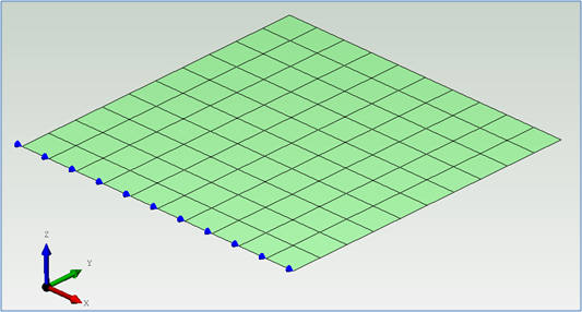
Blue symbols indicate displacement constraints. The following figure shows X global movement constrained.
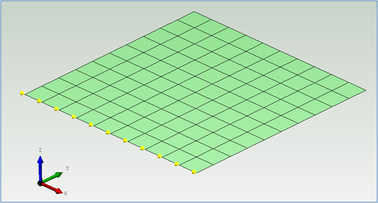
Yellow symbols indicate rotation constraints. The following figure shows X global rotation constrained.
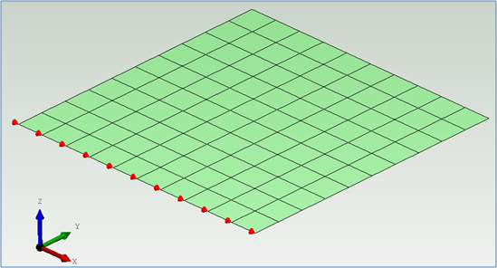
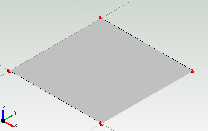
Red symbols indicate both displacement and rotation constraints. The following figure shows both degrees of freedom (movement and rotation) constrained.
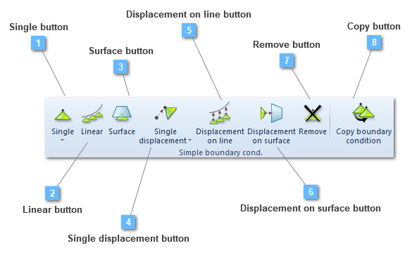
Single button
Add a single boundary condition to the group
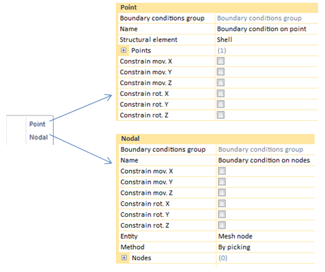
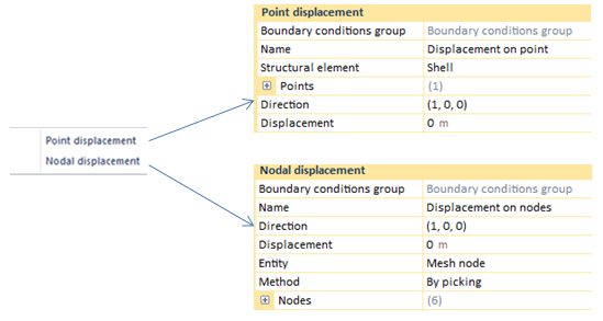
Single boundary conditions can be defined either by points or by nodes. If a single BC is defined by points, the user would be able to define a list of points so as to apply this load. Otherwise, if a single BC is defined by nodes, the node list will be performed by the structural element nodes that are created in the mesh process. The user may fix the number of nodes that will be created.
Both point and node charts show the boundary conditions types that the user will be able to choose from.
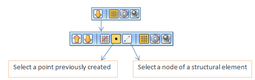
A remarkable aspect is that when the user selects introducing BC by points or nodes, the HUD will be shown in the following way:
If the user wants to use the selection tools, it will be necessary to click on the down arrow in order to see the second selection tool where the point or node selection box could be activated.
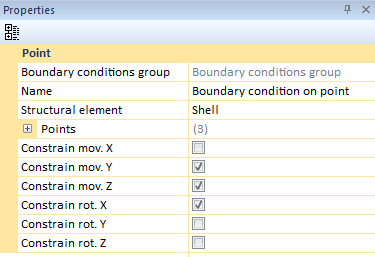
Point Boundary Condition (BC)
Single BC will be applied to points. Click on an existing (it can be edited later manually to set different coordinates, the restriction will be transferred to the finite element model accordingly).
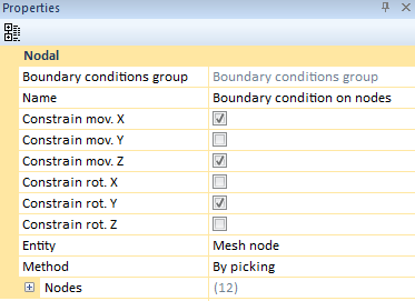
Nodal Boundary Condition (BC)
Single nodal BC will be applied to nodes. Take into account that if mesh is cleared then the Node List will be cleared.
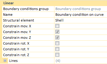
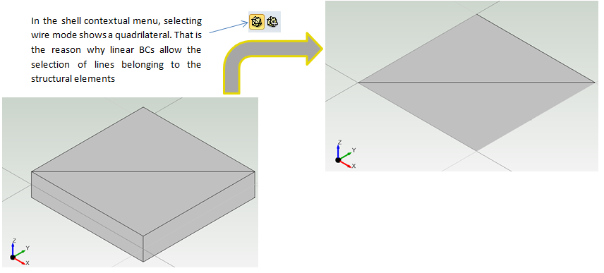
Linear boundary condition assigns a BC to a linear component of a structural element. If the selected structural element is not linear, CivilFEM will give the chance of selecting a group of lines that would perform a line list. If the selected element is a linear one, CivilFEM will apply the linear BC across the whole element.
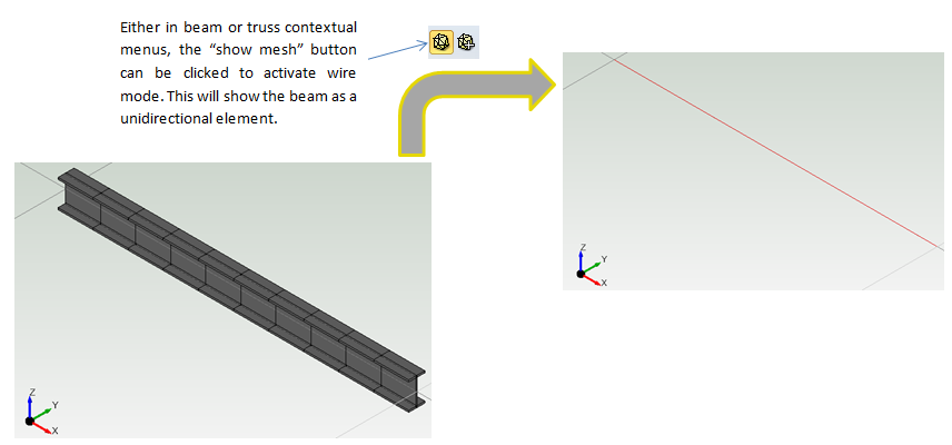
By "linear element" we are referring either to beams or trusses, for instance.
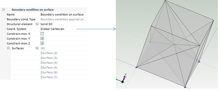
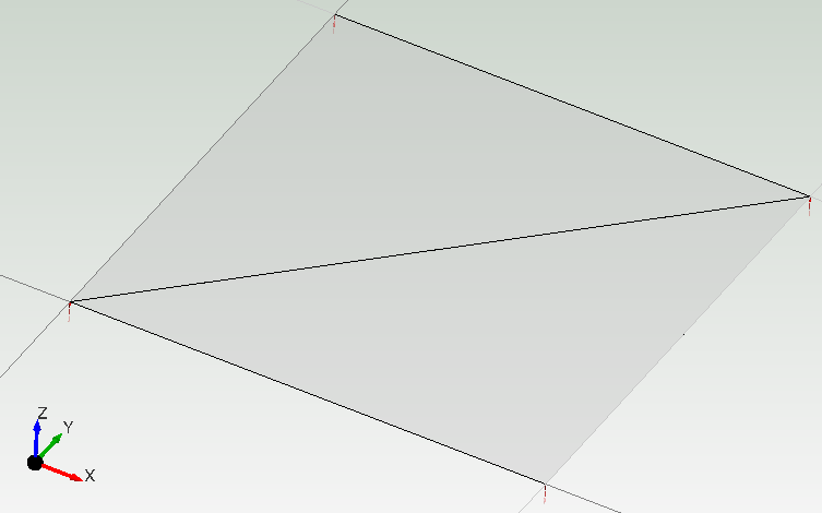
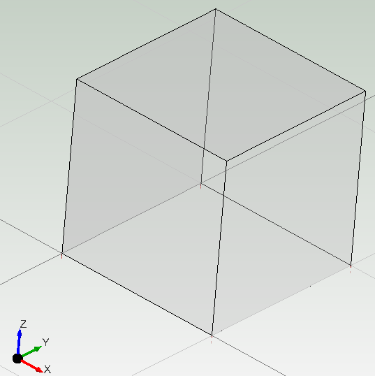
If the structural element is not linear (a shell for instance).
Once this process has been done, the user may choose any existing BC type.
Displacements are applied in order to simulate different situations, such as differential seats or shrinkage and creep.
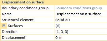
A single displacement in a support, can be introduced either by points or by nodes. If the user wants to define displacements by points, it is necessary to select the structural element where the BC will be applied, besides a point list and the displacement direction. The last step would be specifying the displacement value.
On the other hand, if the displacement designation is done by nodes, although both options are different in appearance, the concept is the same. In displacements by nodes, both the displacement direction and the displacement value have to be entered by the user.
Another remarkable aspect is that when the user chooses entering BCs by points or nodes, the HUD will be visualized in the following way:
If the user wants to use the selection tools, it will be necessary to click on the down arrow in order to see the second selection tool where the point or node selection box could be activated.
Displacements are applied in order to simulate different situations, such as differential seats or shrinkage and creep.
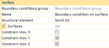
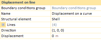
"Displacement on line" assigns a BC to a linear component of a structural element. If the selected structural element is not linear, CivilFEM will give the chance of perform a list of lines that shapes the perimeter of the structural element. If the selected element is a linear one, CivilFEM will apply the linear BC across the whole element.
By "linear element" we are referring either to beams or trusses, for instance.
If the structural element is not a linear element (a shell for instance).
Once the user has selected where displacements will be applied, both the displacement direction and the displacement value can be chosen.
Displacements will be taken into account in the solving process.