Before deleting a geometric entity user must be aware of the hierarchy of solid model and finite element model entities. A lower order entity cannot be deleted if it is attached to a higher-order entity. Thus, a point cannot be deleted if it is attached to a line, an area cannot be deleted if it has been meshed or belongs to a structural element, a volume was involved in a boolean operation and so forth.
Geometric attributes
Once the geometric entity is created geometric attributes are generated as well. These attributes depend on each entity:
Bounding box X-axis
It refers to the X-axis coordinate pair of a projected box with the smallest measure (area, volume) within which all the points lie.
Bounding box Y-axis
It refers to the Y-axis coordinate pair of a projected box with the smallest measure (area, volume) within which all the points lie.
Bounding box Z-axis
It refers to the Z-axis coordinate pair of a projected box with the smallest measure (area, volume) within which all the points lie.
Chord length
Length of the straight line between the start and end vertex.
Curve length
Length of the curve.
Number of vertices
Number of vertices.
A curve is a general vector function of a single parametric variable 1. It can have many types of mathematical forms. (X,Y,Z) = function (1)
A curve has two points, one at each end.
A parametric coordinate (1) whose domain is from 0.0 at P1 (its origin) to 1.0 at P2.
Axis tool is toroughly used in some "Primitive" geometries, "Multiple copy" options as "Rotation" or "Translation-Rotation" and both "Extrude" and "Revolve" tools.
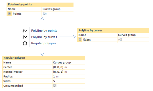
A polyline consists of line segments drawn between consecutive points. This CivilFEM utility may be executed by means of three options:
Polyline by points: the polyline is modeled by joining those points which shape the points list, by means of curves. This "Curves group" selection, in the geometry entity, would activate the whole group curves which shape the polyline.
Polyline by curves: the polyline is proceeded with the outline of curves that have been put together into the "edges" list selection. This "Curves group" selection, in the geometry entity, would activate the whole group curves which shape the polyline.
Regular polygon: the polyline is carried out through a regular polygon, either circumscribed or inscribed. A new "Curves group" would be created in the geometry entity.
The spline curve interpolates a list of vertex points. The creation process of a spline curve consists of entering a sequence of control points.A spline curve is constructed passing throughthem. In order to change the shape of this polynomial curve, two parameters can be modified: degree and continuity.
Polynomials have the general form:
Polynomial degree corresponds to the highest coefficient that is nonzero. Degree 0 (constant), degree 1 (linear), degree 2 (quadratic), degree 3 (cubic), …
Continuity describes the smoothness where the curves join (parametric or geometric continuity).
The shape of the curve depends on the degree of the polynomial, therefore the program will interpolate between a Min. and a Max. set degree.
A third degree polynomial is the most typically used for constructing smooth curves in computer graphics. It is used because of being the least polynomial degree that can support an inflection point. It is also very well behaved numerically meaning that the curves will usually be smooth.
When complex curves with a higher degree need to be created, polynomials tend to be very sensitive to the positions of the control points and thus do not always generate smooth shapes. Smoothness can be described by Continuity at the joints.
Parametric continuity (C) of a spline refers to the continuity of coordinate functions and smoothness for both the curve and its parameters.
Geometric continuity (G) is continuity of the curve itself.
The bezier curve is defined by a list of control points. The curve will, in general, not pass through the control points. Bezier curves always passes through the first and last control points and lies within the convex hull (smallest convex region containing points) of the control points. This curve type adds adjustable weights to provide closer approximations to arbitrary shapes.
Below, an 8 point line will be created in order to show the tool operation. Some weights will be changed to illustrate differences between weights.
As shown, transitions will be softer depending on the weight assigned to different points.
An arc may be defined by means of a circumference through its center point and two endpoints (starting point and point defining the angle), even by two points and a radius as well (starting, ending, auxiliar point and a radius) or, lastly, by three points (starting, ending and intermediate points).
If Arc option is clicked, "Arc (P,P,C)" is selected by default.
Arc (P,P,C)
Defines an arc with two points of the circumference and the center. Direction option is able to reverse the arc´s direction.
Arc (P,P,R)
Defines an arc with two points, an auxiliary point and the radius. The auxiliary point defines the rotation direction depending on the location of the point.
A circumference defined by its center and radius, even by three points as well or, lastly, by means of two points and its center. Otherwise, an ellipse curve is defined by its center and half-axis or by its center point and two endpoints.
If the Circumference or Ellipse button is clicked, the option "Circumf. (C,R)" is selected by default.
Circumf. (C,R)
Defines a circumference using the center, a normal vector and a radius. The circumference is created in the plane normal to the entered vector.
Circumf. (P,P,P)
Defines a circumference using three points.
Circumf. (C,P,P)
Defines a circumference using the center and two points. These three points define the plane in which the circumference will be created.
Ellipse (C,n,e)
Define an ellipse using the center, a normal vector, the major axis direction and both the major and minor radius.
Ellipse (C,P,P)
Define an ellipse using the center and two points.