Before deleting a geometric entity user must be aware of the hierarchy of solid model and finite element model entities. A lower order entity cannot be deleted if it is attached to a higher-order entity. Thus, a point cannot be deleted if it is attached to a line, an area cannot be deleted if it has been meshed or belongs to a structural element, a volume was involved in a boolean operation and so forth.
Geometric attributes
Once the geometric entity is created geometric attributes are generated as well. These attributes depend on each entity:
Bounding box X-axis
It refers to the X-axis coordinate pair of a projected box with the smallest measure (area, volume) within which all the points lie.
Bounding box Y-axis
It refers to the Y-axis coordinate pair of a projected box with the smallest measure (area, volume) within which all the points lie.
Bounding box Z-axis
It refers to the Z-axis coordinate pair of a projected box with the smallest measure (area, volume) within which all the points lie.
Area
Area of the entity.
Number of edges
Number of edges.
Number of vertices
Number of vertices.
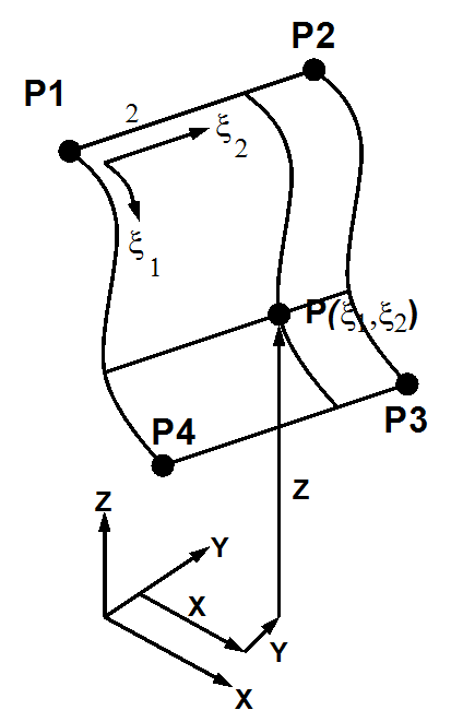
A simple surface is a general vector function of two parametric variables 1 , 2
(X,Y,Z) = function (1, 2)
A simple surface has 3 or 4 bounding edges.
A parametric origin and parametric coordinates whose domains are in the range [0, 1]
A simple surface with 3 visible edges has a fourth degenerated edge.
Surfaces defined by connecting points must be input in a clockwise or counterclockwise order around the surface. This order also determines the positive normal direction of the area according to the right-hand rule and the curves numbering order.
A surface defined by its four vertices, a square by three points and its side length or a square defined by one point, its normal vector and side length.
Quad (P,P,P,P)
Define a quadrilateral surface by four points.
Quad (P,P,P)
Define a quadrilateral surface by three points and its size. Point 1 defines the quadrilateral center; point 2 defines the X axis half-distance; point 3 defines Y axis half-distance; size parameter multiplies these half-distances for creating the quadrilateral.
Quad (P,n)
Define a quadrilateral surface using: one point, a normal vector and its size.
A circle is defined by its center point and two endpoints (starting point and point defining the angle) or by three points (starting, ending and intermediate points). Otherwise, an ellipse is defined by its center and half-axis or by its center point and two endpoints.
Circle (C,R,n)
Defines a circle using the center, a normal vector and a radius. The circle is created in the plane normal to the entered vector.
Circle (C,P,P)
Defines a circle using the center and two points. These three points define the plane in which the circle will be created.
Ellipse(C, P, P)
Define an ellipse using the center and two points.
The Angle establishes the surface angle, 360º being a complete circle.
Surface defined by a list of straight line segments between a list of points.
Regular Polygon
Define a regular polygon using: the center, a vector normal to the plane containing the polygon and the circumference radius. The "Sides" option defines the number of sides that the polygon will have.
"Circumscribed" tool defines if polygon is circumscribed or inscribed to a circumference.
By closed polyline
Define a surface shaped by a polyline. The Polyline can be used to create both a regular polygon and an irregular one.
By curves
Define a surface shaped by a closed set of lines. Lines can be used both to create a regular polygon and an irregular one.
Surface defined by spline curves. The design process of a Spline surface consists of defining a point cloud, or points list, that will act as a support for the Spline surface. The point cloud adjustment is done depending on polynomial degree and surface continuity, specified by the user. Thus, if the the user wants to change the shape of this polynomial surface, these parameters must be readjusted.
Continuity describes the smoothness where the surfaces join (parametric or geometric continuity).
Shape of surface depends on the polynomial´s degree, therefore program will interpolate between a Min. and a Max. set degree.
When complex surfaces with high degree needs to be constructed, polynomials tend to be very sensitive to the positions of the control points and thus do not always make smooth shapes. Smoothness can be described by Continuity at joints.
Parametric continuity (C) of a spline means that continuity of coordinate functions, smoothness both of the surfaces and of its parameterizations.
Geometric continuity (G) is continuity of the surface itself.
As it was previously said a cloud point is necessary to be created. Thus, both in "Num. U" and "Num.V" boxes, points in X and Y direction have to be entered. Num U is related to the X axis while Num V is attached to Y axis.
For instance, a point cloud will be visualized:
So, in this case, Num U= 3 whereas Num V= 4. This values are the point cloud dimensions.
Another remarkable step is selecting all points starting from points in Num V direction (Y axis). Order in which points must be entered is specified ahead. The example will be visualized ahead.
Surface defined by Bezier curves. Bezier surface tool defines a surface that is related to a point cloud, that is, a points list. Every point of that point cloud has a weight parameter that is linked to the curvature degree.
In the Bezier surface properties there are some parameters that will be explained below:
Both "Num. U" and "Num. V" parameters are related to the divisions in the local X and Y axis, respectively. Thus, the number of points in the X and Y direction that defines the point cloud dimensions have to be entered. This will be illustrated in an example:
So, in this case, Num U= 3 whereas Num V= 4.
Now the user needs to select the points starting from points in Num V direction (Y axis). The order in which the points must be entered is specified below.
Once the points are entered, the next step consists of entering all their weights. As stated previously, the weights will be taken into account in the surface curvature calculation. Below both the weights and the final geometry are shown.
The more the weight, the bigger the surface curvature.
A hollow cylinder defined by the center of its base, radius and height or by the centers of its bases and a point on its lateral surface. A cylindrical surface sector can be created by changing the truncation angle (by default 360º).
Cone
A hollow cone defined by the center of its base and radius.
Sphere
A hollow sphere defined by its center point and radius. A spherical surface sector can be created by changing the angle in the U parametric direction (by default 360º) and the angle in the V parametric direction (by default 180º).
Box
A hollow box defined by its vertex and dimensions or by two opposite vertices.
Torus
A hollow torus is defined by the coordinates of the center, an axis, Both of the radius and an ending angle. A toroidal surface sector can be created by changing the portion angle (by default 360º).
Create a surface on top of other existing surface, with a given area
Sew surfaces tool allows the user to establish a new surface from a group of selected surfaces. Those surfaces must be sharing a union element between them, that is, either a point or a line.
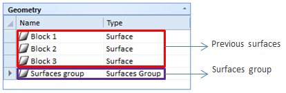
The concept is easy to understand, for instance, here we have a group of surfaces:
It is noticeable that two of those surfaces are linked by its edge while the third surface will be attached by its vertex to the previous ones. Then, the sew surface option is selected:
Once this utility has been executed, the geometry entity group would has the appearance described ahead:
Therefore, if the three blocks would be hidden with button in their contextual menu, the surfaces group geometry would be entirely showed.