|
|||||
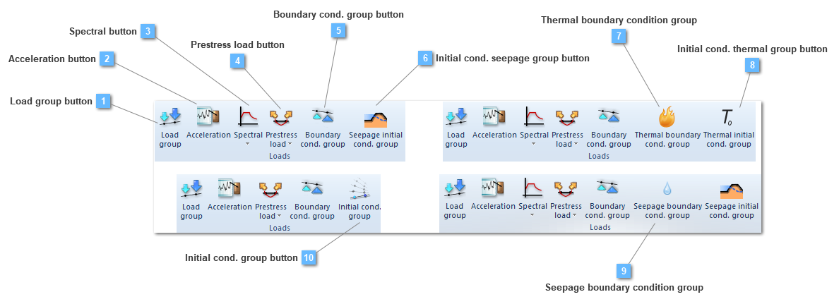
Initial cond. seepage group button
Creates a initial seepage conditions group
This type of load group allows establishing a new initial seepage conditions, submitting the structural element, or any of them, to a specific initial condition. Due to be a seepage condition, this value will depend on seepage units. Initial seepage conditions groups are similar to the seepage boundary conditions groups in the sense that they are applied over any structural element.
Seepage initial condition button will be available as long as a static structural or a seepage analysis are being carried out.
The properties bar menu is visualized ahead:

This condition will be significant, especially, in coupled analysis. This will be more explained in the seepage initial condition contextual menu.
This condition is very useful in case the user would like to establish an initial condition of water level. Nevertheless seepage initial conditions would be only functional in case of taking place a Mohr coulomb, Cam clay or even a nonlinear elastic behavior.
|
Thermal boundary condition group
Creates a thermal boundary conditions group.
Thermal boundary condition group button will be only available if a thermal analysis is being carried out.

There are two types of Boundary Conditions both in transient and static/steady state analysis: nodal temperatures and nodal/element heat fluxes. In this last mentioned ,nodal/element group, the temperature flux, the convective BCs and the radiation, may be included.
CivilFEM includes in the Boundary Conditions list, these which are defined ahead:
Nodal temperatures
Nodal/Element temperatures
This list of boundary conditions will be widely detailed in the Simple boundary condition group toolbar, inside the Thermal boundary condition chapter.
Prescribed nodal temperatures are constant with time unless a time dependent table is referenced. The same situation happens if the user requires to introduce a flux, this one would be constant with time unless a a time dependent table is referenced.
That is, table would have the appearance ahead for the heat transfer:

This dependent table is configured in the defined material (only if the analysis is a thermal one). For further information, consult the material toolbar menu.
Thermal analysis only needs the existence of thermal boundary conditions, that is, structural boundary conditions are no required, unless a structural analysis has to be carried out as well.
|
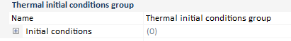
Initial cond. thermal group button
Creates a initial thermal conditions group
This type of load group allows establishing a new initial thermal conditions, submitting the structural element, or any of them, to a specific initial condition. Due to be a thermal condition, this value will depend on temperature units. Initial thermal conditions groups are similar to the thermal boundary conditions groups in the sense that they are applied over any structural element.
Thermal initial condition button will be only available if a thermal analysis is being carried out.
The properties bar menu is visualized ahead:
This condition will be significant, especially, in coupled analysis. This will be more explained in the thermal initial condition contextual menu.
|
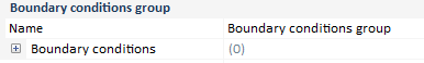
Seepage boundary condition group
Creates a seepage boundary conditions group.
Seepage boundary condition group button will be only available if a seepage analysis is being carried out.
There are two types of Boundary Conditions both in transient and static/steady state analysis: nodal total heads and nodal/element hydraulic fluxes.
CivilFEM includes in the Boundary Conditions list, these which are defined ahead:
Nodal temperatures
Nodal/Element temperatures
This list of boundary conditions will be widely detailed in the Simple boundary condition group toolbar, inside the Seepage boundary condition chapter.
Prescribed nodal total heads are constant with time unless a time dependent table is referenced. The same situation happens if the user requires to introduce a hydraulic flux, this one would be constant with respect time unless a a time dependent table is referenced.
This dependent table is configured in the defined material (only if the analysis is a seepage one). For further information, consult the material toolbar menu.
Porous material is shape by the conditions ahead:

Being the Kh and the mv coefficients, the hydraulic conductivity and the coefficient of volume compressibility, respectively.
Seepage analysis only needs the existence of seepage boundary conditions, that is, structural boundary conditions are no required, unless a structural analysis has to be carried out as well.
|