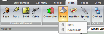
Menu

Model Utils toolbar

Model Utils toolbar
1

Connection button

1. Connection button
Apply connection on nodes
 
Connections are a very useful way of tying nodes of the model between them. This can be used to distribute a load between several adjacent nodes, for example, or to tie the movement of several nodes among themselves.
 
By default this model util will tie all freedom degrees of tied nodes as a rigid link to the master node.
 
If "By coefficient" option is selected, then ui = Coeff*ufor the freedom degree selected will be used to create the tying equation.
 
For instance:
 
We want to tie the center node of a hole in a plate with the surrounding nodes of the hole. After creating the plate and the hole that goes through the plate, we create the connection:
 
First step will consist of clicking on "Connection" in Mesh tab.
 
 
Secondly, the user has to select the Master node to which all nodes are going to be connected.
 
Then, the selected tied nodes are put together into a list. Control-click can be used to select several nodes.
 
 
By last, connection type (Rigid, By coefficient, By spring, Uncoupled) can be accessed through the properties of the created connection.
 
 
2

Mass button

2. Mass button
Create a mass
 
CivilFEM provides a "Mass" utility which allows the definition punctual masses applied at a point or node.
 
Mass utility has six degrees of freedom: translations in the nodal x, y, and z directions and rotations about the nodal x, y, and z axes.
 
Those model utils are defined by a concentrated by a single point over a defined structural element.
 
When visualizing mass entities the user see grey spheres in the place where the command has been executed. An example is added ahead:


Mass properties bar is structured as follows:
 
 
In this chart, it is also available to modify the mass imposed conditions.
 
The total mass, provided in a point or in a node, will correspond to the addition of Mass X, Mass Y and Mass Z. This is because although the masses are not mobilized, their existence implies an increasing in the weight of the structure.
 
Every introduced mass will be taken into account in the structural mass calculation. Mass result will be available, once the user has solved the model and has loaded the results, in the Information button. This button is located in the List toolbar.
 
3

Insertion button

3. Insertion button
Create an insertion
 
When generating the model, it is typical to define the relationships among different degrees of freedom by using elements to connect the nodes. However, sometimes user needs to be able to model distinctive features other special internodal connections which cannot be adequately described with elements. Such special associations among nodal degrees of freedom can be established by using coupling and constraint equations. This technique enables the user to link degrees of freedom in ways that elements cannot.
 
CivilFEM provides an Insertion model definition option which allows the definition of host bodies and lists of elements or nodes to be inserted in the host bodies. The degrees of freedom of the nodes in the inserted element list are automatically tied using the corresponding degrees of freedom of the nodes in host body elements based on their isoparametric location in the elements.
 
The degrees of freedom of the nodes in the inserted structural element are automatically tied using the corresponding degrees of freedom of the nodes in host body elements based on their isoparametric location in the elements.
 
The Insertion model definition option can be used to place reinforcing bars into solid elements. It also can be used to link two different meshes.
 
For instance, next image represents how a tendon structural element is inserted inside a solid Torus (host) and both DOFs are tied together.
 
 
Transformation must not be used at any nodes of host body elements and at inserted nodes, unless the same set of local coordinate system is used for all nodes involved.
 
To define an Insertion three data are needed:
 
  • First Structural: element as host element.
  • Second Structural: element as element to be inserted.
  • Exterior Tolerance: a node is considered within a host element if the distance between the element and the node is smaller than the tolerance times average edge length of the element, unless the node is actually inside another host element. Default is 0.05.
 
In this chart, it is also available to modify the insertion imposed conditions.
 
In other instance, in CivilFEM, the multiple insertion option is also available. That is, the user may insert more than one structural element into a host element.
 
Just like in the non-multiple insertion, the exterior tolerance would be fixed in the properties bar options.
 
It would be available, as well, to select more than one host element, that is, insertions could belong to different structural elements.
 
 
4

Spring button

4. Spring button
Create a spring
 
A spring is an elastic tool that is used to store mechanical energy and which retains its original shape after a force is removed. Springs are typically defined in a stress free or “unloaded” state. This means that no longitudinal loading conditions exist unless preloading is specified. Those are defined as longitudinal and they connect two bodies together or connect a body to ground. Longitudinal springs generate a force that depends on linear displacement. Six types of springs are available:
The force in a linear mechanical spring is given by:
 
 
Spring stiffness units are Force/Length.
 
A point spring can be defined in three ways:
 
  • Fixed DOF: spring has two nodes, and the stiffness/force is dependent upon the displacement in the prescribed direction.
  • To Ground: spring has a single node, and the stiffness/force is dependent upon the displacement in the fixed direction.
  • True Direction: spring has two nodes, and the stiffness/force is along a line between the two nodes. The direction is updated with deformation if Large Strain is activated.
 
A preload in the spring may be specified through an initial force input. If the degrees of freedom are specified as zero for a mechanical run, the spring acts along the line joining the two nodes. This line direction is updated during an incremental stress analysis only if large displacement is flagged.
 
If the second node is specified as zero, the spring is assumed to be fixed to ground along the specified degree of freedom. The displacement of the ground along the specified degree of freedom is assumed to be zero.
 
For linear spring case, k constant for each node is computed as follows (Linear structural element with 2 elements and three nodes):
 
 
For surface spring case, k constant for node A is computed as follows (structural element with a quadrilateral and triangular elements), for plan view:
 
 
For nonlinear springs the stiffness can be varied as a function of relative displacement or angle. In this case, initial force capability is disabled. For dynamic analysis, a nonlinear spring damping table is available (force versus relative velocity). Dashpot damping is obtained from gradient values.
 
Relative displacement (or velocity) is taken as follows:
 
  • Springs defined by means one degree of freedom between two nodes:
DOF Increment of node 2 – DOF Increment of node 1.
  • To ground springs: – DOF Increment of node 1.
  • True direction: DOF is the relative location of the two nodes, positive displacement if they get further and negative if the get closer.
 
For rotational springs a rotational or torsional stiffness K is used (Force*length/angle) and a different cordinate system can be used to define the spring directions. For rotational springs a nonlinear stiffness (moment vs relative rotation table) is available as well.
 
Activation and Deactivation Time can be set for all Spring types to be taken into account in construction stage analyses.


5

Remesh button

5. Remesh button
Edit Remesh options for a structural element, if remesh is requiered:
 
6

Crack Definition

6. Crack Definition
Define the properties of the crack definition:
 
Crack Tip node/ Crack tip node path: Defines the node (2D model) or the nodes (3D model) for the beginning of the crack
 
Crack grow method: Define the way the crack is produced:    
 
  • Remeshing based growth: Crack growth by means of remeshing is available for 2-D solid elements, shells and 3-D solid elements (need remesh option).
     
  • Growth by mesh cutting: For this option, the crack can grow arbitrarily through a 2-D or shell mesh without global remeshing. Nodes are shifted and elements are split up in order to create the cut and to improve the mesh.
     
  • Growth along element edges or faces: For this option, the crack can grow along element edges for 2-D and shell elements and along faces for 3-D elements. The
    element edge or face closest to the crack growth direction is used. New nodes are automatically inserted and the element connectivity is changed for elements around the crack tip in order to grow the crack
     
    Crack propagation mode:
     
  • Fatigue Crack Growth : Here we specify a maximum growth increment, which is scaled between different cracks and along crack fronts. Each time the end of the fatigue load cycle is reached, the crack will grow according to this specification
 
  • Direct Crack Growth: Here, the goal is to determine the load at which a crack will grow and which path it will take when it grows. In direct growth crack propagation nothing happens with the crack until a crack growth criterion is fulfilled
     
 
Maximum crack growth increment: Maximum value of crack growth when crack propagation mode is set to fatigue
 
Fatigue time period : Time after that a crack growth is performed
 
High cycle fatigue calculation:  Option to calculate the number of fatigue cycles from the information collected in a fatigue calculation. In order to activate this we select the High Cycle Fatigue Calculation option in the fatigue settings menu and enter the parameters for Paris law.