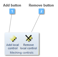
Add button
Add a local mesh control to the structural element
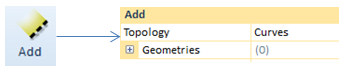
Add tool is commonly used in order to apply local mesh conditions to the shell structure. The allowed controls in shells are only available for curves.
Other alternative is to use the target number of elements to control element size. Only the approximate number of the elements can be reached.
In many cases, the mesh produced by default element sizes is not be appropriate due to the physical characteristics of the structure. In special cases including models with stress concentrations or singularities, user will have to get more involved with the meshing process and can gain better results by using the local meshing controls.
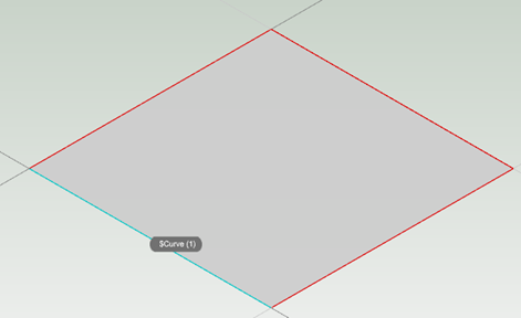
When a local mesh control is required to be entered, CivilFEM allows to set those ones in the edges of the shell. It may be possible to selected from 1 to as many edges as the shell would have.
In this case only one edge has been selected, therefore in the rest of edges, the global mesh controls will be applied.
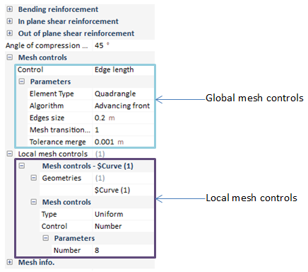
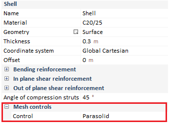
This local mesh control is visualized beneath the "mesh controls" options, inside the shell properties bar.
$Curve (1) is referred to an auxiliary geometry created when the surface were modeled. As can be noted, parameter number has been changed from 10 to 8, so the rest of edges will be meshed under global mesh controls.
The shell were modeled to be 1 x 1 m so, if global mesh conditions are applied, edges get divided into 5 parts (1/0.2). Therefore, the edge in which local mesh controls are applied, get divided into 8 parts, just as it was ordered.
On the other hand, in Mentat versions, from 2016 onwards, assigning local mesh controls on non-auxiliary geometry is available as well. This option is only functional, both in shells and solids, in Parasolid meshes.
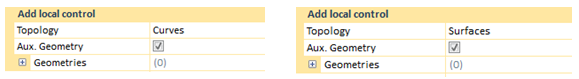
The local mesh options allow the user to select controls on non-auxiliary lines or surfaces.
It could be required to set local controls on these lines, plotted on the shell surface. CivilFEM only gets the user to access to the non-auxiliary geometry if the "Aux. Geometry" check is deactivated.
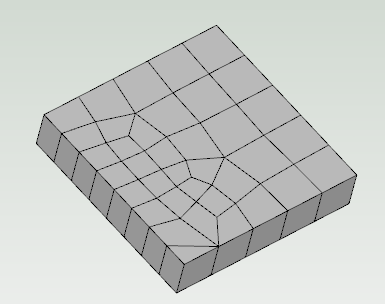
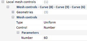
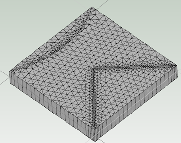
When all this process is carried out, a new item is entered in the local mesh control drop. Inside, the curves mesh controls are available in order to be updated, depending on the user preferences. In this case, the control will be applied by number, besides assigning a parameter of 60.
Therefore, here is the result of applying the local mesh controls, previously described.
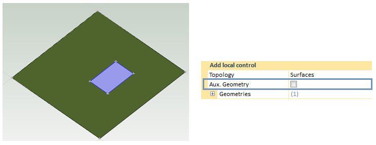
To put it the other way round, now a new surface will be taken as non-auxiliary geometry. As it was previously said, CivilFEM only allows the user to access to this geometry type if the "Aux. Geometry" check is deactivated.
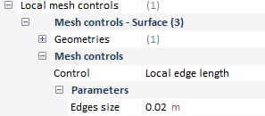
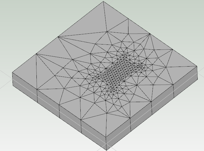
Again, a new item has been entered in the local mesh control drop. Now it belongs to a local control mesh in a surface, so 0.02 meters is entered as parameter of its local edge length.
Therefore, mesh is plotted ahead.
|