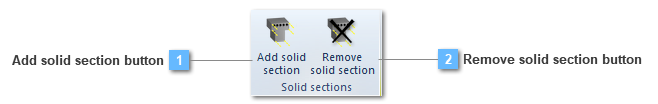
Add solid section button
Add a solid section to the structural element
If the user needs to define a section which is non defined on the predefined CivilFEM´s menu, this utility will be very useful.
This option allows user creating a new section apart from a solid structural element. On the other hand, it will be only necessary to assign a coordinate system and CivilFEM will take the properly section.
Once this operation has been carried out, the program will have created a new section which has been shaped by means of the solid previously created.
This section is attached to a similar contextual menu than other sections, therefore it will be available to be reinforced if it is a concrete section. For further information about sections, check the cross section toolbar.
This section would be available in order to be attached to another structural element, however, this is another utility but not necessary so as to obtain solid section results.
In addition, this utility could be only carried out in case a concrete material shapes the section.
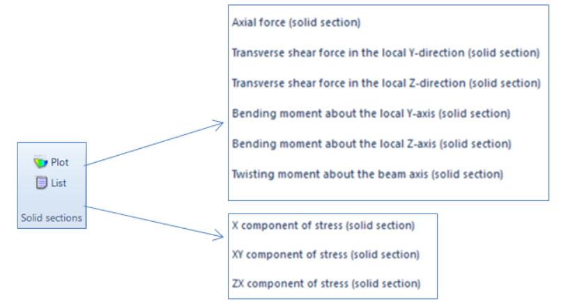
After establishing the load state and solving the model, in the results ribbon, concretely in the Solid Section part, two new options can be visualized: the plot and the list options.
The plot tool shows the results in a visual manner so as that the user can realize of the distribution by means of the colored legend, while the list tool comes out a table with the name, the ID and the force and moment values of the solid section.
In regard to the results visualization, these will be plotted in a border window instead of in the model view window. This window will be shaped: in first by the plot with its result values, secondly by the results drop downs and, finally, by the forces and moments result values.
On the other hand, we can see that the axis of the solid section are included in the plot visualization. Therefore, the forces and moments will be provided in reference to those.
Beneath, the different utility of the drop downs will be detailed:
-
The section drop down allows to select the different created solid sections.
-
In the results drop downs, the user will be able to order the plotting of any result contained on the results drop. Moreover, if the mouse is brought near the plotted section, the appropriated value for the section, on that point, will be visualized.
-
In the unit drop the user can change the units the different values are provided.
-
By last, the plot drop down allow the user to know where the solid section is locate. This will be get then selecting the option "Structural element" in the Plot drop. The next image visualize this previously described information.
|