|
|||||
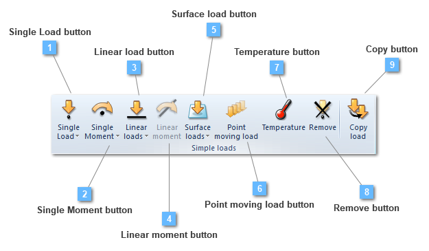


Single Moment button
Add a moment to the load group
Single moments are concentrated moments applied over any structural element, not necessarily at an already existing point or node. Selected points, or nodes depending on the application method, will perform the points list on which the load is going to be applied. If there is no attached node, the moment is interpolated between the nearest existing nodes.

Most of the required data needed to create a single moment, both by points or nodes, will be defined below.
Different moments applied at the same location are always accumulated.
The main difference between creating a load by points or by nodes is that "by points" is done using geometry entities while "by nodes" is done using the nodes of a structural element.
Another remarkable idea is that defining the load by nodes grants the opportunity of selecting more than one entity, whereas defining the load by points only allows the selection of a single point.
In regards to the loads property bar, it is subject to change depending on the chosen analysis type.
For instance, if we have a static, modal or buckling analysis, the load property bar does not change.

Nevertheless, the properties bar will be submitted to some changes if a transient analysis is carried out. For instance, the load will be dependent on time, becoming necessary to establish a function in order to indicate the load behavior along the whole process.

On another instance, when establishing a harmonic analysis, two different type of loads may be defined: either harmonic or prestressing loads.

Both types can be explained by this expression:

If the structural analysis requires harmonic loads, both the first and second term will exist. Nevertheless, if prestressing loads are required for the structural analysis, the second term will be 0.

These are the property bars for both harmonic and prestressing loads. As it can be seen, harmonic loads include a phase parameter while prestressing loads do not.
 | ||||||||||
Linear load button
Add a linear load to the load group
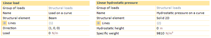
Linear loads button manage to establish the load type in order to enter: whether a load or a hydrostatic pressure.

On the one hand, the linear load option is able to shape either linear loads or linear hydrostatic pressures. While a linear load is able to be applied over a line attached to a linear (truss or beam), a shell or even in a 2D and 3D solid structural element, the linear hydrostatic pressure will be only possible to be applied over 2D models, that is, only if the structural element is a linear one or a 2D solid.
. The calculated equivalent nodal forces are obtained by equally lumping the uniformly distributed loads onto the nodes. The calculated equivalent nodal forces are obtained by equally lumping the uniformly distributed loads onto the nodes.
Linear load utility is able to apply a specific load value into a line list, that is, over a group of lines. Different linear loads applied at the same location are always accumulated.
In regard to the linear load, if the current structural element is a truss or a beam, there will be only a line over which the load can be applied. However, if the structural element is a shell, or either a 2D or a 3D solid, the user will be able to choose the line in order to apply that load.
The application of this load type depends on the analysis. For instance, if we have a static, modal or buckling analysis, the load property bar does not change.

Linear loads can be non-uniform, having different values at each end with a linear variation, that is the reason why Load at end I and Load at end J parameters are available to changes.
Required data for linear load application are ahead:
Nevertheless, the properties bar will be submitted to some changes if a transient analysis is carried out. For instance, the load will be dependent on time, becoming necessary to establish a function in order to indicate the load behavior along the whole process.
In a transient analysis, "Factor at end I" and "Factor at end J" are set instead of "Load at end I" and "Load at end J". Both factors I and J allow the user to enter non-uniform loads.

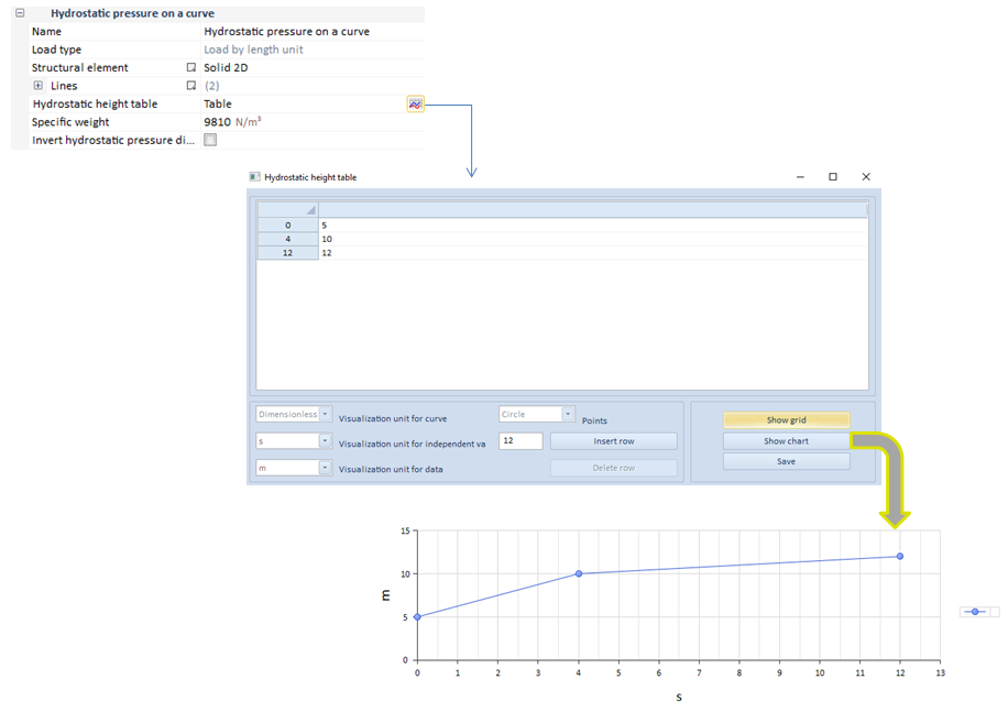
However, in respect with the linear hydrostatic pressure, this follows the same assumption than the linear load. That is, on a linear truss or beam structural elements, only a line will be accessible to be selected whereas, on a 2D solid, one or more lines that shape the structural element, could be attached.

This will be the appearance of its properties bar on a static, buckling, modal or harmonic analysis. However, on a transient analysis, the hydrostatic height will be dependent on time, becoming necessary to establish a function in order to indicate the load behavior along the whole process.
Required data for surface hydrostatic pressure application are:
On another instance, when establishing a harmonic analysis, two different type of loads may be defined: either harmonic or prestressing loads.
Both types can be explained by this expression:
If the structural analysis requires harmonic loads, both the first and second term will exist. Nevertheless, if prestressing loads are required for the structural analysis, the second term will be 0.

These are the property bars for both harmonic and prestressing loads. As it can be seen, harmonic loads include a phase parameter while prestressing loads do not.
| ||||||||||||||||||||||||
Surface load button
Add a surface load
Surface loads button manage to establish the load type in order to enter: whether a load or a hydrostatic pressure.
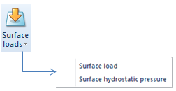
On the one hand, the surface load option shapes distributed or pressure loads applied over a surface attached to a shell or a solid structural element. The calculated equivalent nodal forces are obtained by equally lumping the uniformly distributed loads onto the nodes. On the other hand, shaping a surface hydrostatic pressure is also possible.
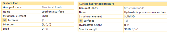
In regard to the surface load, if the current structural element is a shell, there will be only a surface over which the load can be applied. However, if the structural element is a solid, the user will be able to choose the surface in order to apply the load.

Required data for surface load application are:
The application of this load type depends on the analysis. For instance, if we are carrying out a static, modal or buckling analysis, the properties bar of the load does not change.

Nevertheless, the properties bar will be submitted to some changes if a transient analysis is carried out. For instance, the load will be dependent on time, becoming necessary to establish a function in order to indicate the load behavior along the whole process.

On another note, glancing over the load properties bar, there are two concepts that have not been detailed yet: the orientation and the gradient of this surface load.
Orientation: defines the load direction.

If the user selects "Parallel to a vector" as orientation, the load will be applied using the specified direction. Nevertheless, if "Normal to the surface" orientation is chosen, loads will always be applied perpendicular to the selected surface. "Normal to the surface" orientation is very common in curved surfaces or irregular sections.
Gradient: specifies a slope for the surface load.
If the user is required to perform a gradient slope in a surface load, both the slope value and a line taken as a reference in order to determine the gradient direction, must be specified.

However, in respect with the surface hydrostatic pressure, this follows the same assumption than the surface load. That is, on a shell structural element, only a surface will be accessible to be selected whereas, on a solid, one or more surface that shape the structural element, could be attached.

This will be the appearance of its properties bar on a static, buckling, modal or harmonic analysis. However, on a transient analysis, the hydrostatic height will be dependent on time, becoming necessary to establish a function in order to indicate the load behavior along the whole process.

Required data for surface hydrostatic pressure application are:
On another instance, when establishing a harmonic analysis, two different type of loads may be defined: either harmonic or prestressing loads.
Both types can be explained by this expression:
If the structural analysis requires harmonic loads, both the first and second term will exist. Nevertheless, if prestressing loads are required for the structural analysis, the second term will be 0.

These are the properties bars for both harmonic and prestressing loads. As it can be seen, harmonic loads include a phase parameter while prestressing loads do not.
| ||||||||||||||||||||||
Point moving load button
Add a point moving load
The point moving load option creates dynamic loads dependent on time, that go along a structural element line. The user can assign the initial time when the load to be applied starts, as well as the load speed.
This tool is only available in a transient analysis.

Apart from defining the direction and the load value, it is necessary to assign a path (line of application), the initial time in which the load starts acting, the speed at which the load goes along the structural element and the number of steps.
An example is shown:
The case consist of a shell in which a 10000 N dynamic load is applied.
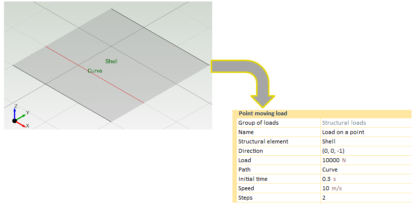
The moving load characteristics have been defined. The load case is going to be applied during 1 s, so the initial time has been fixed to a calculation time period of (0.3s).
Path (curve) where the load is applied. If the user wants to apply the moving load in another curve that does not belong to the shell, it has to be entered as another geometric entity. In this case, moving loads will be applied on the "curve" line .
Speed at which the loads will travel the path will be 10 m/s.
2 steps have been defined, so two loads will be set an both ends and another one will be set in the middle of the curve.

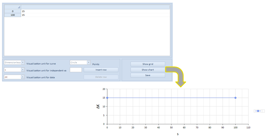
Moving load data can be changed by the user. Any change can be applied using the grid options.

As it is shown in the different charts, CivilFEM is auto calculating the equivalent loads during the specified time.
Moving loads are used in several engineering cases such as bridges.
Finally, times assigned to the different loads must be carefully chosen in conjunction with the time that will be set in the load case. If the user wants to obtain the maximum moment in a structural element, it is necessary to fix the time of the load case with the time in the structural element section in which the moving load has its maximum values. This process is used to evaluate influence lines.
| ||||||||||||||
Temperature button
Add a temperature increment or decrement to the load group
Structural temperature increment (C, F, K) can be defined in all structural elements. For shell structural elements the user can define different temperature increments on both top and bottom faces. The local Z axis of the shell element determines the top/bottom face. (Positive local z direction indicates the top face and negative indicates the bottom face).
On the other hand, beam structural elements only allow the application of one temperature increment because it is a linear element.
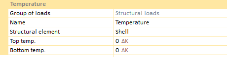 
Required data for temperature load are as follows:
This chart shows the required data for shells. If it referred to a beam structural element, the chart would have only one increment.
Application of this type of load depends on the analysis. For instance, if the required analysis is static, modal or buckling, the load property bar does not change. Examples will be presented by means of a beam structural element.

Nevertheless, the properties bar will be submitted to some changes if a transient analysis is carried out. For instance, the load will be dependent on time, becoming necessary to establish a function in order to indicate the load behavior along the whole process.
On another instance, when establishing a harmonic analysis, two different type of loads may be defined: either harmonic or prestressing loads.
In spite of having the possibility to choose between harmonic or prestressing loads, temperature chart doesn't need to change.
 | ||||||||||