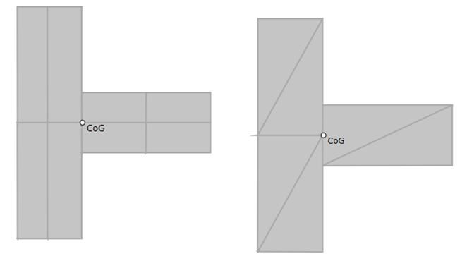
Generic concrete sections
CivilFEM gives the user the chance of defining a new concrete section in case of requiring a different one from which are defined on the program menu. This can be carried out by two different procedures:
-
-
Defining the section by means of the tesselate.
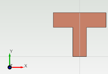
Capturing a concrete section by a surface
The first step in order to define a concrete captured section is to create a new surface. This surface will be an auxiliar one, being this the concrete cross section assigned to the mesh linear structural element.
The captured concrete section window will be visualized ahead.
To perform this, it will be only necessary to create a new concrete material, along with the previous so called auxiliar surface, to be created. The "Size" parameter is refered to the distance between tessellas.
Once this process has been finished, the new available captured section can be assigned to a linear structural element, that is, both for a beam and a truss structural element.
On the other hand, in order to perform this cross section type, the surface has to be defined in the XY plane.
Furthermore, it is necessary to clarify that there is a limit for the number of tessella inside a captured section. This limit will be 25 tessella. If the element size set by the user gives more than 25 tessella (pre-integrated), element results (stresses and strains) will not be available for the linear structural element with the captured section associated.
Pre-integrated sections can only use elastic material behavior and cannot account for any plasticity. The model will be solved but their results will correspond with a elastic analysis.
Defining a concrete section by points
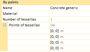
CivilFEM allows the user to perform a concrete cross section by defining its tessellate. That is, this tool requires the points of tessellas to be entered. The concrete generic cross section properties bar will be visualized ahead.
To perform this, it will be only necessary to create a new concrete material, along with the definition of the points of the tessellas of this new section. Every tessella will be shaped by four points, therefore the will be only necessary to click on them so as to define the tessellate.
A new cross section by point instance will be carry out beneath:
In first instance, it is mandatory to say that the surface has to be defined in the XY plane.
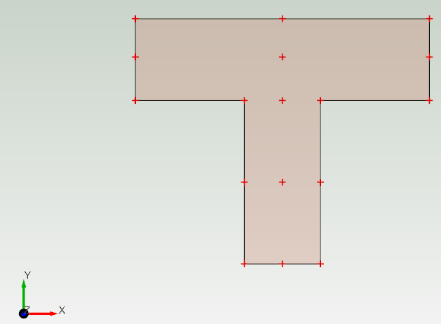
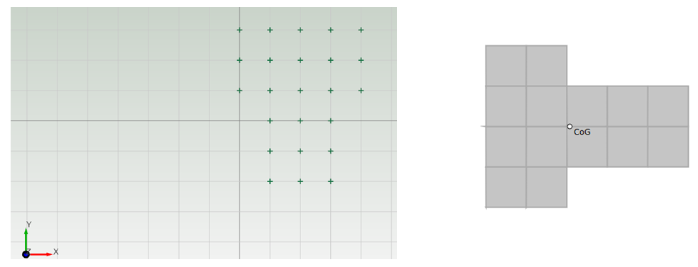
In order to perform this task more simply, both a new surface and the tessellate vertexes have been created so, the user will only have to click on the points, four by four and CivilFEM will design this section.
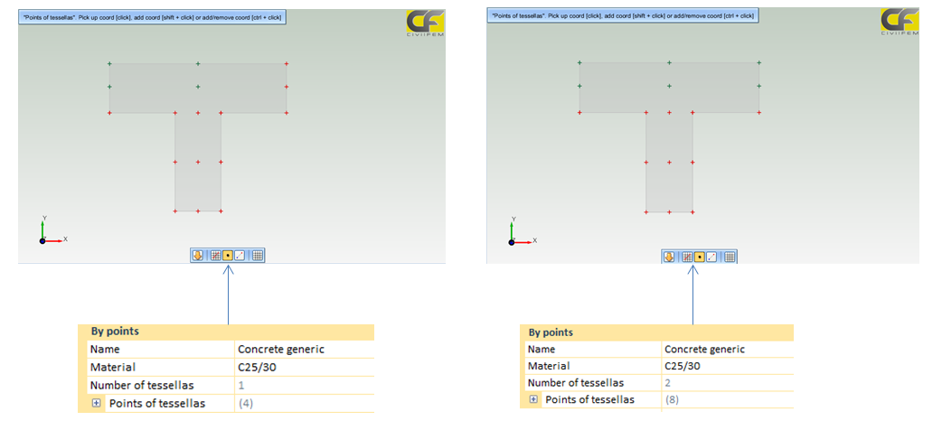
In the first image, only one tessella has been already selected, whereas in the second image, there have been selected two of them. This can be visualize on the "Number of tessellas" property.
-
To pick a new point click on it.
-
To add a new point press shift and click at a time.
-
To add/remove a point, press ctrl and click at a time.
If the user requires to add the same point to the point of tessellas list, due to be shared by different tessellas, the combo shift and click will be used.
The first image beneath will visualize the whole process fulfilled by plotting the cross section with the tessellate.
In addition, as seen in the second image above, there is the possibility of defining a triangular tessellate. This can be achieved by clicking twice on the last point in order to complete the four points per tessella.
Moreover, it would be possible to select points from the grid directly, just as in the image ahead:
Once this process has been finished, the new available captured section can be assigned to a linear structural element, that is, both for a beam and a truss structural element.
On the other hand, there are some rules and conventions when defining this general section:
-
Each quadrilateral segment is defined by entering the coordinates of the four corner points in the local XY-plane.
-
The corner points must be entered in a counterclockwise sense.
-
The quadrilateral segments must describe a simply connected region; i.e., there must be no holes in the section, and the section cannot be composed of unconnected “islands” and should not be connected through a single point.
-
The quadrilateral segments do not have to match at the corners. Internally, the edges must, at least, partly match.
-
The segments must not overlap each other (i.e., the sum of the areas of each segment must equal the total area of the segment).
-
A section cannot have more than 100 integration points in total. This limits each section to, at most, 100 segments that, by necessity, will use single point integration. If less than 100 segments are present in a section, they may use higher order integration schemes, as long as the total number of points in the section does not exceed 100.

