
3.2. Finite Element Technology
3.4.5. Construction process analysis
3.5.2. Pardiso Direct Sparse method
4.2.4. Tensors and associated invariants
4.2.5. Forces and moments in beams
4.2.6. Generalized strains in beams and trusses
4.2.7. Forces and Moments in Shells
4.2.8. Generalized Strains in Shells
4.7. Checking and Design results
5.1.1. Forces and Moments Sign Criteria
5.1.2. Reinforcement Directions
5.1.4. Axial + Bending Check and Design
5.2.1. Hypothesis of the Calculation
5.2.2. Calculation Process of the Reinforcement Design Moments
5.3.2. Equivalent Forces and Moments for Reinforcement Calculation
5.3.5. Reinforcement Checking in Intermediate Layer
5.4. Design according to the Orthogonal Directions Method
5.4.2. Design Forces and Moments
5.4.3. Maximum Allowable Stress/Strain in Reinforcement
5.5. Out-of-Plane Shear Load according to EC2 and ITER
5.5.2. Out-of-Plane Shear Checking
5.5.3. Out-of-Plane Shear Design
5.6. Out-of-Plane Shear Load according to Structural code (Spanish code)
5.6.2. Out-of-Plane Shear Checking
5.6.3. Out-of-Plane Shear Design
5.7. Out-of-Plane Shear Load according to ACI-318-05
5.7.2. Out-of-Plane Shear Checking
5.7.3. Out-of-Plane Shear Design
5.8. Out-of-Plane Shear Load according to ACI-318-14
5.8.2. Out-of-Plane Shear Checking
5.8.3. Out-of-Plane Shear Design
5.9. Out-of-Plane Shear Load according to ACI-349-01
5.9.2. Out-of-Plane Shear Checking
5.9.3. Out-of-Plane Shear Design
5.10. Out-of-Plane Shear Load according to EHE-08
5.10.2. Out-of-Plane Shear Checking
5.10.3. Out-of-Plane Shear Design
5.11. In-Plane Shear Load according to ACI 349-01
5.11.2. In-Plane Shear Checking for Walls
5.11.3. In-Plane Shear Design for Walls
5.11.4. In-Plane Shear Checking for Slabs (Seismic Loads)
5.11.5. In-Plane Shear Design for Slabs (Seismic Loads)
5.12. Cracking Checking according to Eurocode 2 (EN 1992-1-1:2004/AC:2008)
5.12.2. Reinforcement Stress Calculation
5.13. Cracking Checking according to Structural Code (Spanish code)
5.13.2. Reinforcement Stress Calculation
5.14. Cracking Checking according to ACI 318-05 and ACI 318-14
5.14.2. Reinforcement Stress Calculation
Chapter 6 Reinforced Concrete Sections
6.2.2. Diagram Construction Process
6.2.3. Determination of the Diagram Center
6.3. Axial Load and Biaxial Bending Checking
6.4. Axial Load and Biaxial Bending Design
6.5. Axial Force and Biaxial Bending Calculation Codes
6.5.1. Eurocode 2, ITER Design Code and Structural Code (Spanish code)
6.5.10. Australian Standard 3600
6.5.12. Brazilian Code NBR6118
6.5.13. AASHTO Standard Specifications for Highway Bridges
6.5.15. Russian Code SP 52-101
6.6.1. Previous considerations
6.6.2. Shear and torsion code properties
6.6.3. Code Dependent Parameters for Each Section
6.6.4. Shear and Torsion according to Eurocode 2 (EN 1992-1-1:2004/AC:2008) and ITER Design Code.
6.6.5. Shear and Torsion according Structural Code (Spanish Code)
6.6.6. Shear and Torsion according to ACI 318-05
6.6.7. Shear and Torsion according to ACI 318-14
6.6.8. Shear and Torsion according to ACI 349-01 and ACI349-06
6.6.9. Shear and Torsion according to BS8110
6.6.10. Shear and Torsion according to GB50010
6.6.11. Shear and Torsion according to AASHTO Standard Specifications for Highway Bridges
6.6.12. Shear and Torsion according to NBR6118
6.6.13. Shear and Torsion according to EHE-08
6.6.14. Shear and Torsion according to IS 456
6.7.1 Cracking according to Eurocode 2 (EN 1992-1-1:2004/AC:2008)
6.7.2 Cracking according to Structural Code (Spanish code)
6.7.3 Cracking according to ACI 318-05
Chapter 7 Code Check for Structural Steel Members
7.1. Steel Structures According to Eurocode 3
7.1.4. Structural steel code properties
7.1.6. Section Class and Reduction Factors Calculation
7.1.7. Checking of Members in Axial Tension
7.1.8. Checking of Members in Axial Compression
7.1.9. Checking of Members under Bending Moment
7.1.10. Checking of Members under Shear Force
7.1.11. Checking of Members under Bending Moment and Shear Force
7.1.12. Checking of Members under Bending Moment and Axial Force
7.1.13. Checking of Members under Bending, Shear and Axial Force
7.1.14. Checking for Buckling of Members in Compression
7.1.15. Checking for Lateral-Torsional Buckling of Beams Subjected to Bending
7.1.17. Critical Forces and Moments Calculation
7.2. Steel Structures According to AISC ASD/LRFD 13th Ed.
7.2.3. Structural steel code properties
7.2.6. Checking of Members for Tension (Chapter D)
7.2.7. Checking of Members in Axial Compression (Chapter E)
7.2.8. Compressive Strength for Flexural Buckling
7.2.9. Compressive Strength for Flexural-Torsional Buckling
7.2.10. Compressive Strength for Flexure
7.2.11. Checking of Members for Shear (Chapter G)
7.2.12. Checking of Members for Combined Flexure and Axial Tension / Compression (Chapter H)
7.2.13. Checking of Members for Combined Torsion, Flexure, Shear and/or Axial Force (Chapter H)
7.3. Steel Structures According to British Standard 5950
7.3.5 Structural steel code properties
7.3.7 Section Class and Reduction Factor Calculation.
7.3.8 Checking of Bending Moment and Shear Force (BS Article 4.2)
7.3.9 Checking of Lateral Torsional Buckling Resistance (BS Article 4.3)
7.3.10 Checking of Members in Axial Tension (BS Article 4.6)
7.3.11 Checking of Members in Axial Compression (BS Article 4.7)
7.3.12 Tension Members with Moments (BS Article 4.8.2)
7.3.13 Compression Members with Moments (BS Article 4.8.3)
7.4. Steel Structures According to ASME BPVC III Sub. NF
7.4.4 Structural Steel Properties
7.4.10 Axial Compression & Bending Checking
7.5. Steel Structures According to GB50017
7.5.4 Structural steel code properties
7.5.5 Cross Section Type Classification
7.5.9 Bending & Shear Checking
7.5.11 Bending & Axial Checking
7.5.12 Compression Buckling Checking
7.6. Steel Structures According to IS800-07
7.6.3 Structural steel code properties
7.6.5 Section Class and Reduction Factors Calculation
7.6.6 Checking of Members in Axial Tension
7.6.7 Checking of Members under Bending Moment
7.6.8 Checking of Members under Shear Force
7.6.9 Checking of Members under Bending Moment and Shear Force
7.6.10 Checking of Members under Bending Moment + Axial Force and Bi-axial Bending + Axial Force
7.6.11 Checking for Buckling of Compression Members
7.6.13 Checking for Lateral-Torsional Buckling of Members Subjected to Bending and Axial Compression
7.6.14 Critical Forces and Moments Calculation
7.7. Steel Structures According to AASHTO LRFD (2012)
7.7.4. Section Class and Reduction Factors Calculation
7.7.5. Members Subjected to Compression
7.7.6. Members Subjected to Bending
7.7.7. Members Subjected to Tension
7.7.8. Members Subjected to Axial Compression
7.7.9. Members Subjected to Flexure
7.7.10. Members Subjected to Shear
7.7.11. Members Subjected to Combined Forces
7.8. Steel Structures According to AISC ASD/LRFD 14th Ed.
7.8.3. Structural steel code properties
7.8.6. Checking of Members for Tension (Chapter D)
7.8.7. Checking of Members in Axial Compression (Chapter E)
7.8.8. Compressive Strength for Flexural Buckling
7.8.9. Compressive Strength for Flexural-Torsional Buckling
7.8.10. Compressive Strength for Flexure
7.8.11. Checking of Members for Shear (Chapter G)
7.8.12. Checking of Members for Combined Flexure and Axial Tension / Compression (Chapter H)
7.8.13. Checking of Members for Combined Torsion, Flexure, Shear and/or Axial Force (Chapter H)
7.9. Steel Structures According to Structural Code (Spanish code)
7.1.4. Structural steel code properties
7.1.6. Section Class and Reduction Factors Calculation
7.1.7. Checking of Members in Axial Tension
7.1.8. Checking of Members in Axial Compression
7.1.9. Checking of Members under Bending Moment
7.1.10. Checking of Members under Shear Force
7.1.11. Checking of Members under Bending Moment and Shear Force
7.1.12. Checking of Members under Bending Moment and Axial Force
7.1.13. Checking of Members under Bending, Shear and Axial Force
7.1.14. Checking for Buckling of Members in Compression
7.1.15. Checking for Lateral-Torsional Buckling of Beams Subjected to Bending
7.1.17. Critical Forces and Moments Calculation
8.2. Spectrum Calculation according to Eurocode 8
8.3. Spectrum Calculation according to NCSE-2002
8.4. Combination of modes and directions
8.4.1. Complete Quadratic Combination Method (CQC)
8.4.2. Square Root of the Sum of the Squares
8.4.3. Combination of maximum modal values
Chapter 9 Miscellaneous Utilities
9.1. Parameters and Expressions
9.2. CivilFEM Python Programming
Welcome to the Theory Manual for CivilFEM Powered by Marc. This manual presents the theoretical descriptions of every calculation procedure used by the program and describes the relationship between the input data and the results given by CivilFEM. This manual is essential for understanding how the program calculates results as well as how to interpret the results correctly.
The Theory Manual provides the theoretical basis of the algorithms included in the program. With knowledge of the underlying theory, the user can perform analyses efficiently and confidently on CivilFEM by using the capabilities to their full potential while being aware of the limitations.
Reading the whole manual will not be necessary; it is recommended to read only the paragraphs containing the specific algorithms being utilized.
Take into account that there is a online CivilFEM help manual.
· MSC. Software Help Documentation
Linear finite element analysis is characterized by a force-displacement relationship that only contains linear terms. Linear system of equations always produces a unique solution while in nonlinear analysis does not guarantee a unique solution. In fact, there may be multiple solutions or no solution at all. The task of providing analysis directives (i.e. controls by which the program will come to a solution) is far from simple. Solving nonlinear equations is an incremental and iterative process.
A linear static structural analysis with a known external load can be performed in one step. If nonlinearities are expected, it may be necessary to apply the load in increments and let each load increment iterate to the equilibrium state, within a specified tolerance, using a particular iteration scheme such as Newton-Raphson.
In this CivilFEM Theory Manual version only linear static loads are considered. In the figure below there is an example of loading workflow covering all that civil engineering needs.

The word loads in CivilFEM terminology includes load groups, accelerations, spectra and boundary conditions.
Linear analysis is the type of stress analysis performed on linear elastic structures. Because linear analysis is simple and inexpensive to perform and generally gives satisfactory results, it is the most commonly used structural analysis.
Nonlinearities due to material, geometry, or boundary conditions are not included in this type of analysis. The behavior of an isotropic, linear, elastic material can be defined by two material constants: Young’s modulus, and Poisson’s ratio.
CivilFEM allows user to perform linear elastic analysis using any element type in the program. Various kinematic constraints and loadings can be prescribed to the structure being analyzed; the problem can include both isotropic and anisotropic elastic materials.
The principle of superposition holds under conditions of linearity. Therefore, several individual solutions can be superimposed (summed) to obtain a total solution to a problem.
Linear analysis does not require storing as many quantities as does nonlinear analysis; therefore, it uses the core memory more sparingly.
This section describes the basic concepts of finite element technology. CivilFEM solver was developed on the basis of the displacement method. The stiffness methodology used addresses force-displacement relations through the stiffness of the system.
The force displacement relation for a linear static problem can be expressed as:
Ku = f
Where is the system stiffness matrix, is the nodal displacement, and is the force vector.
Assuming that the structure has prescribed boundary conditions both in displacements and forces, the governing equation can be written as:
![]()
![]() is the unknown
displacement vector,
is the unknown
displacement vector, ![]() is the prescribed force vector,
is the prescribed force vector,![]() is the prescribed
displacement vector, and
is the prescribed
displacement vector, and ![]() is the reaction force. After solving for the displacement vector,
the strains in each element can be calculated from the strain-displacement
relation in terms of element nodal displacement as:
is the reaction force. After solving for the displacement vector,
the strains in each element can be calculated from the strain-displacement
relation in terms of element nodal displacement as:
![]()
The stresses in the element are obtained from the stress-strain relations as:
![]()
Where ![]() and
and ![]() are stresses and
strains in the elements, and
are stresses and
strains in the elements, and ![]() is the displacement
vector associated with the element nodal points;
is the displacement
vector associated with the element nodal points; ![]() and L are
strain-displacement and stress-strain relations, respectively.
and L are
strain-displacement and stress-strain relations, respectively.
In a dynamic problem, the effects of mass and damping must be included in the system. The equation governing a linear dynamic system is:
M![]()
![]() + Ku = f
+ Ku = f
Where M is the system mass matrix, D is the damping matrix, following equation is the acceleration vector, and is the velocity vector. The equation governing an undamped dynamic system is:
M![]() + Ku = f
+ Ku = f
The equation governing undamped free vibration is:
M![]() + Ku = 0
+ Ku = 0
Natural frequencies and modal shapes of the structural system are calculated using this equation.
K![]()
![]()
CivilFEM’s dynamic analysis capability allows the user to perform the following calculations:
1. Modal analysis.
2. Harmonic analysis.
3. Spectrum analysis.
4. Transient analysis.
Damping and nonlinear effects, including material nonlinearity, and boundary nonlinearity, can be incorporated. All nonlinear problems should be analyzed using direct integration methods.
CivilFEM uses the Lanczos method to extract eigenvalues (natural frequencies) and eigenvectors (mode shapes), optimal for several modes. After the modes are extracted, they can be used in a transient analysis or spectrum response calculation.
In dynamic eigenvalue analysis, we find the solution to an undamped linear dynamics problem:
![]()
Where K is the stiffness matrix, M is the
mass matrix, ![]() are the
eigenvalues (frecuencies) and
are the
eigenvalues (frecuencies) and ![]() are the
eigenvectors. In CivilFEM, if the extraction is performed after increment zero,
K is the tangent stiffness matrix, which can include material and geometrically
nonlinear contributions. The mass matrix is formed from both distributed mass
and point masses.
are the
eigenvectors. In CivilFEM, if the extraction is performed after increment zero,
K is the tangent stiffness matrix, which can include material and geometrically
nonlinear contributions. The mass matrix is formed from both distributed mass
and point masses.
The Lanczos algorithm converts the original eigenvalue problem into the determination of the eigenvalues of a tri-diagonal matrix. The method can be used either for the determination of all modes or for the calculation of a small number of modes. For the latter case, the Lanczos method is the most efficient eigenvalue extraction algorithm. A simple description of the algorithm is as follows. Consider the eigenvalue problem:
![]()
Previous equation can be rewritten as:
![]()
Consider the transformation:
u ![]() Q
Q ![]()
Substituting last equation into previous
one and premultiplying by the matrix ![]() on both sides of the
equation, we have:
on both sides of the
equation, we have:
![]()
The Lanczos algorithm results in a transformation matrix Q such that:
![]()
![]()
where the matrix T is a symmetrical tri-diagonal matrix of the form:

Consequently, the original eigenvalue problem is reduced to the following new eigenvalue problem:
![]()
The eigenvalues can be calculated by the standard QL-method.
Within CivilFEM it can be selected either the number of modes to be extracted, or a range of modes to be extracted. The Sturm sequence check can be used to verify that all of the required eigenvalues have been found.
In addition, user can select the lowest frequency to be extracted to be greater than zero.
Eigenvalue extraction is controlled by the maximum number of iterations for all modes in the Lanczos iteration method in convergence controls.
After the modal shapes (and frequencies) are extracted, it is allowed to recover stresses and reactions for a specified number of modes during a modal or a buckling analysis.
The stresses are computed from the modal displacement vector φ ; the nodal reactions are calculated from:
![]()
The nodal vector of modal mass is calculated as m = Mφ.
The participation factor for a given mode is defined as
![]()
Where:
|
cnj |
is the participation factor for mode n in the jth direction. |
|
|
is the eigenvector value for mode n and degree of freedom i. |
|
|
is the mass matrix. |
|
|
Defines the magnitude of the rigid body response of degree of freedom i to impose rigid body motion in the jth direction and takes the following form:
|
Where:
|
X, Y, and Z |
are the coordinates of the respective node. |
|
|
are the coordinates of center of rotation. |
|
|
is the unit vector (carrying 1 for row j and the rest being zeros) |
The effective modal masses are calculated as squares of the participation factors.
![]()
Where ![]() is the effective
modal mass for mode n in the jth direction.
is the effective
modal mass for mode n in the jth direction.
While the nodal vector of modal masses gives the significance of mass participation of the node for the given mode in the given direction, the effective modal mass gives an idea about the mass contribution of the whole structure (or model) for the mode in the given direction.
Any sustained cyclic load will produce a sustained cyclic response in a structural system. Harmonic response analysis gives the ability to predict the sustained dynamic behavior of structures, thus enabling to verify whether or not designs will successfully overcome resonance, fatigue, and other harmful effects of forced vibrations.
Harmonic response analysis allows to analyze structures vibrating around an equilibrium state. This equilibrium state can be unstressed or statically prestressed. Statically prestressed equilibrium states can include material and/or geometric nonlinearities. User can compute the damped response for prestressed structures at various states.
In many practical applications, components are dynamically excited. These dynamic excitations are often harmonic and usually cause only small amplitude vibrations. CivilFEM linearizes the problem around the equilibrium state. If the equilibrium state is a nonlinear, statically prestressed situation, CivilFEM considers all effects of the nonlinear deformation on the dynamic solution. These effects include the following:
• Initial stress.
• Change of geometry.
• Influence on constitutive law.
The vibration problem can be solved as a linear problem using complex arithmetic.
The analytical procedure consists of the following steps:
1. CivilFEM calculates the response of the structure to a static preload (which can be nonlinear) based on the constitutive equation for the material response. In this portion of the analysis, the program ignores inertial effects.
2. CivilFEM calculates the complex-valued amplitudes of the superimposed response for each given frequency, and amplitude of the boundary tractions and/or displacements. In this portion of the analysis, the program considers both material behavior and inertial effects.
3. You can apply different loads with different frequencies or change the static preload at your discretion. All data relevant to the static response is stored during calculation of the complex response.
The small amplitude vibration problem can be written with complex arithmetic as follows:
![]()
![]()
![]()
Where:
![]()
![]() is the complex
response vector,
is the complex
response vector,
![]()
![]() is the complex load
vector,
is the complex load
vector,
![]() ,
,
![]() is the excitation
frequency.
is the excitation
frequency.
K![]()
Where:
![]() are element
stiffness matrices,
are element
stiffness matrices,
![]() are the spring
stiffness matrices.
are the spring
stiffness matrices.
![]()
Where:
![]() are element mass
matrices,
are element mass
matrices,
![]() are mass point
contributions
are mass point
contributions
![]()
Where:
![]() are element
damping matrices,
are element
damping matrices,
![]() are damper
contributions,
are damper
contributions,
![]() is
the mass damping coefficient,
is
the mass damping coefficient,
![]() is
the stiffness damping coefficient,
is
the stiffness damping coefficient,
![]() is
the numerical damping coefficient.
is
the numerical damping coefficient.
If all external loads and forced displacements are in phase and the system is undamped, this equation reduces to:
![]()
The element damping matrix (![]() ) can be obtained for
any material with the use of a material damping matrix which allows the user to
input a real (elastic) and imaginary (damping) stress-strain relation. The
material response is specified with the constitutive equation.
) can be obtained for
any material with the use of a material damping matrix which allows the user to
input a real (elastic) and imaginary (damping) stress-strain relation. The
material response is specified with the constitutive equation.
![]()
Where B and C can be functions of deformation and/or frequency.
The global damping matrix is formed by the integrated triple product. The following equation is used:
![]()
Where ![]() is the
strain-displacement relation.
is the
strain-displacement relation.
Similarly, the stiffness matrix K is based on the elastic material matrix B.
The output of CivilFEM consists of stresses, strains, displacements and reaction forces, all of which may be complex quantities. The strains are given by
![]()
and the stresses by
![]()
The reaction forces are calculated with
![]()
The printout of the nodal values consists of the real and imaginary parts of the complex values, but you can request that the amplitude and phase angle be printed.
Harmonic response analysis is a technique used to determine the steady-state response of a linear structure to loads that vary sinusoidally (harmonically) with time. The idea is to calculate the structure's response at several frequencies and obtain a graph of some response quantity (usually displacements) versus frequency.
A harmonic analysis, by definition, assumes that any applied load varies harmonically (sinusoidally) with time. To completely specify a harmonic load, three pieces of information are usually required: the amplitude, the phase angle, and the forcing frequency range.


![]()

The amplitude is the maximum value of the load.
The phase angle is a measure of the time by which the load lags (or leads) a frame of reference. On the complex, it is the angle measured from the real axis. The phase angle is required only if you have multiple loads that are out of phase with each other.
Increments in frequency can be linear or logarithmic:
·
If linear:
![]()
![]()
· If logarithmic increments in frequency:

![]()
The spectrum response capability allows obtaining maximum response of a structure subjected to know spectral base excitation response. This is of particular importance in earthquake analysis and random vibration studies. You can use the spectrum response option at any point in a nonlinear analysis and, therefore, ascertain the influence of material nonlinearity or initial stress.
The spectrum response capability technique operates on the eigenmodes previously extracted to obtain the maximum nodal displacements, velocities, accelerations, and reaction forces. You can choose a subset of the total modes extracted by either specifying the lowest n modes or by selecting a range of frequencies.
Enter the displacement response spectrum ![]() for a particular
digitized value of damping through the RESPONSE SPECTRUM model definition.
CivilFEM performs the spectrum analysis based on the latest set of modes
extracted. The program lumps the mass matrix to produce
for a particular
digitized value of damping through the RESPONSE SPECTRUM model definition.
CivilFEM performs the spectrum analysis based on the latest set of modes
extracted. The program lumps the mass matrix to produce ![]() . It hen obtains the
projection of the inertia forces onto the mode
. It hen obtains the
projection of the inertia forces onto the mode ![]()
![]()
The spectral displacement response for the ![]()
![]()
CivilFEM then calculates the square roots of the sum of the squares as
![]() DISPLACEMENT
DISPLACEMENT
![]() VELOCITY
VELOCITY
![]() ACCELERATION
ACCELERATION
![]() FORCE
FORCE
The internal forces given by Force equation are identified as reaction forces on the post file. The force transmitted by the structure to the supporting medium (also referred to as base shear) is only reported in the out file and is given by
![]() TRANSMITTED
FORCE
TRANSMITTED
FORCE
Transient dynamic analysis deals with an initial-boundary value problem. In order to solve the equations of motion of a structural system, it is important to specify proper initial and boundary conditions. You obtain the solution to the equations of motion by using either modal superposition (for linear systems) or direct integration (for linear or nonlinear systems). In direct integration, selecting a proper time step is very important. For both methods, you can include damping in the system.
The following sections discuss the seven aspects of transient analysis listed below.
1. Direct Integration
2. Time Step Definition
3. Initial Conditions
4. Time-Dependent Boundary Conditions
5. Mass Matrix
6. Damping
Direct integration is numerical method for solving the equations of motion of a dynamic system. It is used for both linear and nonlinear problems. In nonlinear problems, the nonlinear effects can include geometric, material, and boundary nonlinearities. For transient analysis, CivilFEM offers two direct integration operators listed below.
a) Newmark-beta Operator
b) Generalized-Alpha Operator
Consider the equations of motion of a structural system:
![]()
where M, C, and K are mass, damping, and stiffness matrices, respectively, and a, v, u, and F are acceleration, velocity, displacement, and force vectors. Various direct integration operators can be used to integrate the equations of motion to obtain the dynamic response of the structural system. The technical background of the two direct integration operators available in CivilFEM is described below.
a) Newmark-Beta Operator
This operator is probably the most popular direct integration method used in finite element analysis. For linear problems, it is unconditionally stable and exhibits no numerical damping. The Newmark-beta operator can effectively obtain solutions for linear and nonlinear problems for a wide range of loadings. The procedure allows for change of time step, so it can be used in problems where sudden impact makes a reduction of time step desirable. This operator can be used with adaptive time step control. Although this method is stable for linear problems, instability can develop if nonlinearities occur. By reducing the time step and/or adding (stiffness) damping, you can overcome these problems.
The generalized form of the Newmark-beta operator is
![]()
![]()
where superscriptn denotes a value at the nth time step and u, v, and a take on their usual meanings.
The particular form of the dynamic equations corresponding to the trapezoidal rule
![]()
results in
![]()
where the internal force R is

Dynamic equation allows implicit solution of the system
![]()
Notice that the operator matrix includes K,
the tangent stiffness matrix, Hence, any nonlinearity results in a
reformulation of the operator matrix. Additionally, if the time step changes,
this matrix must be recalculated because the operator matrix also depends on
the time step. It is possible to change the values of 𝛾
and ![]() through
the global solution controls.
through
the global solution controls.
b) Generalized Alpha Operator
One of the drawbacks of
the existing implicit operators is the inability to easily control the
numerical dissipation. While the Newmark-Beta method has no dissipation and
works well for regular vibration problems. A single scheme that easily allows
zero/small dissipation for regular structural dynamic problems and high-frequency
numerical dissipation for dynamic contact problems is desirable. In (Chung, J.
and Hulbert, G.M., “A time integration algorithm for structural dynamics
with improved numerical dissipation: The Generalized-α Method”,
Journal of Applied Mechanics, Vol. 60, pp. 371 - 375, June 1993) a Generalized-alpha
method has been presented as an unconditionally stable, second-order algorithm
that allows user-controllable numerical dissipation. The dissipation is
controlled by choosing either the spectral radius S of the operator or
alternatively, two parameters ![]() and
and
![]() .
The choice of the parameters provides a family of time integration algorithms
that encompasses the Newmark-Beta and the Hilber-Hughes-Taylor time integration
methods as special cases.
.
The choice of the parameters provides a family of time integration algorithms
that encompasses the Newmark-Beta and the Hilber-Hughes-Taylor time integration
methods as special cases.
The equilibrium equations for the generalized alpha method can be expressed in the form
![]()
where
![]()
![]()
![]()
The displacement and velocity updates are identical to those of the Newmark algorithm
![]()
![]()
where optimal values of the parameters ![]() and 𝛾 are related to
and 𝛾 are related to ![]() and
and ![]() by
by
![]()
![]()
It is seen that the ![]() and
and ![]() parameters can be
used to control the numerical dissipation of the operator. A simpler measure is
the spectral radius ρ. This is also a measure of the numerical
dissipation; a smaller spectral radius value corresponds to greater numerical
dissipation. The spectral radius of the generalized alpha operator can be
related to the
parameters can be
used to control the numerical dissipation of the operator. A simpler measure is
the spectral radius ρ. This is also a measure of the numerical
dissipation; a smaller spectral radius value corresponds to greater numerical
dissipation. The spectral radius of the generalized alpha operator can be
related to the ![]() and
and ![]() parameters as
follows
parameters as
follows
![]()
![]()
ρ varies between 0 and 1. Accordingly,
the ranges for the ![]() and
and ![]() parameters are given
by
parameters are given
by
![]() and
and ![]() corresponds to a
spectral radius of 0.0.
corresponds to a
spectral radius of 0.0.
It can also be noted that the case of ρ = 1 has no dissipation and corresponds to a mid-increment Newmark-beta operator.
In a transient dynamic analysis, time step parameters are required for integration in time.
Enter parameters to specify the time step size and period of time for this set of boundary conditions.
When using the Newmark-beta operator, decide which frequencies are important to the response. The time step in this method should not exceed 10 percent of the period of the highest relevant frequency in the structure. Otherwise, large phase errors will occur. The phenomenon usually associated with too large a time step is strong oscillatory accelerations. With even larger time steps, the velocities start oscillating. With still larger steps, the displacement eventually oscillates. In nonlinear problems, instability usually follows oscillation. When using adaptive dynamics, you should prescribe a maximum time step.
As in the Newmark-beta operator, the time step in Houbolt integration should not exceed 10 percent of the period of the highest frequency of interest. However, the Houbolt method not only causes phase errors, it also causes strong artificial damping. Therefore, high frequencies are damped out quickly and no obvious oscillations occur. It is, therefore, completely up to the engineer to determine whether the time step was adequate.
For the Generalized-alpha operator, depending on the chosen parameters, the integration scheme can vary between the Newmark-beta operator and the Single-step houbolt operator. For spectral radii < 1, there is artificial damping in the system. Depending on the type of problem, the Generalized-alpha parameters and the associated time step should be carefully chosen to reduce phase errors and effects of artificial damping.
In nonlinear problems, the mode shapes and frequencies are strong functions of time because of plasticity and large displacement effects, so that the above guidelines can be only a coarse approximation. To obtain a more accurate estimate, repeat the analysis with a significantly different time step (1/5 to 1/10 of the original) and compare responses.
Nonlinear analysis is usually more complex and expensive than linear analysis. Also, a nonlinear problem can never be formulated as a set of linear equations. In general, the solutions of nonlinear problems always require incremental solution schemes and sometimes require iterations within each load/time increment to ensure that equilibrium is satisfied at the end of each step. Superposition cannot be applied in nonlinear problems.
Newton-Raphson is the iterative procedures supported in CivilFEM.
A nonlinear problem does not always have a unique solution. Sometimes a nonlinear problem does not have any solution, although the problem can seem to be defined correctly.
Nonlinear analysis requires good judgment and uses considerable computing time. Several runs are often required. The first run should extract the maximum information with the minimum amount of computing time. Some design considerations for a preliminary analysis are:
· Minimize degrees of freedom whenever possible.
· Halve the number of load increments by doubling the size of each load increment.
· Impose a coarse tolerance on convergence to reduce the number of iterations. A coarse run determines the area of most rapid change where additional load increments might be required. Plan the increment size in the final run by the following rule of thumb: there should be as many load increments as required to fit the nonlinear results by the same number of straight lines.
CivilFEM solves nonlinear static problems according to one of the following two methods: tangent modulus or initial strain. Examples of the tangent modulus method are elastic-plastic analysis, nonlinear springs, nonlinear foundations, large displacement analysis and gaps. This method requires at least the following three controls:
· A tolerance on convergence.
· A limit to the maximum allowable number of iterations.
· Specification of a minimum number of iterations.
In many nonlinear analyses, it is useful to have CivilFEM automatically determine the appropriate load step size. For an adaptive scheme, the load step size changes from one increment to the other and also within an increment depending on convergence criteria and/or user-defined physical criteria.
Selecting a proper load step increment is an important aspect of a nonlinear solution scheme. Large steps often lead to many iterations per increment and, if the step is too large, it can lead to inaccuracies and nonconvergence. On the other hand, using too small steps is inefficient.
When a fixed step fraction scheme is used, it is important to select an appropriate step fraction size that captures the loading history and allows for convergence within a reasonable number of recycles. For complex load histories, it is necessary to prescribe the loading through time tables while setting up the run.
For fixed stepping, there is an option to have the load step automatically cut back in case of failure to obtain convergence. When an increment diverges, the intermediate deformations after each iteration can show large fluctuations and the final cause of program exit can be any of the following: maximum number of iterations reached, elements going inside out or, in a contact analysis and nodes sliding off a rigid contact body. If the cutback feature is activated and one of these problems occur, the state of the analysis at the end of the previous increment is restored and the increment is subdivided into a number of subincrements. The step size is halved until convergence is obtained or the user-specified number of cutbacks has been performed. Once a subincrement is converged, the analysis continues to complete the remainder of the original increment. No results are written to the post file during subincrementation. When the original increment is finished, the calculation continues to the next increment with the original increment count and time step maintained.
The Newton-Raphson method can be used to solve the nonlinear equilibrium equations in structural analysis by considering the following set of equations:
![]()
Where u is the nodal-displacement vector, F is the external nodal-load vector, R is the internal nodal-load vector (following from the internal stresses), and K is the tangent-stiffness matrix. The internal nodal-load vector is obtained from the internal stresses as

In this set of equations, both R and K are
functions of u. In many cases, F is also a function of u (for example, if F
follows from pressure loads, the nodal load vector is a function of the
orientation of the structure). The equations suggest that use of the
Newton-Raphson method is appropriate. Suppose that the last obtained
approximate solution is termed ![]() , where
, where ![]() indicates the
iteration number. First equation can then be written as
indicates the
iteration number. First equation can then be written as
![]()
This equation is solved for ![]() and the next
appropriate solution is obtained by
and the next
appropriate solution is obtained by
![]()
Solution of this equation completes one
iteration, and the process can be repeated. The subscript ![]() denotes the
increment number representing the state t = n. Unless stated otherwise, the
subscript n+1 is dropped with al quantities referring to the current
state.
denotes the
increment number representing the state t = n. Unless stated otherwise, the
subscript n+1 is dropped with al quantities referring to the current
state.
The Newton-Raphson method is the default in CivilFEM (see figure below).

The Newton-Raphson method provides good
results for most nonlinear problems, but is expensive for large,
three-dimensional problems, when the direct solver is used. The computational
problem is less significant when the iterative solvers are used. Figure above
illustrates the graphical interpretation of the Newton-Raphson iteration
technique in one dimension to find the roots of the function ![]() starting from
increment 1 where
starting from
increment 1 where ![]() to increment 2 where
to increment 2 where
![]()
The iteration process stops when the convergence criteria are satisfied.
The arc-length procedures assume that the
control of the nonlinear behavior and possible instabilities is due to
mechanical loads, and that the objective is to obtain an equilibrium position
at the end of the loadcase. Hence, while the program may increase or decrease
the load, the load can always be considered to be ![]() , where Fb
and Fe are the loads at the beginning and end of the loadcase. The
scale factor does not necessarily vary linearly from 0 to 1 over the
increments, and may, in fact, become negative.
, where Fb
and Fe are the loads at the beginning and end of the loadcase. The
scale factor does not necessarily vary linearly from 0 to 1 over the
increments, and may, in fact, become negative.
Mechanical loads, as shown above, are applied in a proportional manner and thermal loads are applied instantaneously.

This means that any automatic load incrementation method is limited to mechanical input histories that only have linear variations in load or displacement and thermal input histories that have immediate change in temperature. For example, one may not use a rigid body with a linearly changing velocity, since the resulting displacement of the rigid body would give parabolically changing displacements. In this case, one would need to use a constant velocity for the arc length method to work properly.
For the arc length method, care must be taken to appropriately define the loading history in each loadcase. The load case should be defined between appropriate break points in the load history curve. For example, in figure above, correct results would be obtained upon defining three distinct loadcases between times 0-t1, t1-t2, and t2-t3 during the model preparation. However, if only one load case is defined for the entire load history between 0-t3, the total applied load for the loadcase is zero.
The solution methods described above involve an iterative process to achieve equilibrium for a fixed increment of load. Besides, none of them have the ability to deal with problems involving snap-through and snap-back behavior. An equilibrium path as shown in figure below displays the features possibly involved.

The issue at hand is the existence of multiple displacement vectors, u , for a given applied force vector, F . The arc-length methods provide the means to ensure that the correct displacement vector is found by CivilFEM. If you have a load controlled problem, the solution tends to jump from point 2 to 6 whenever the load increment after 2 is applied. If you have a displacement controlled problem, the solution tends to jump from 3 to 5 whenever the displacement increment after 3 is applied. Note that these problems appear essentially in quasi-static analyses. In dynamic analyses, the inertia forces help determine equilibrium in a snap-through problem.
Thus, in a quasi-static analysis sometimes it is impossible to find a converged solution for a particular load (or displacement increment):
![]()
This is illustrated in previous figure where both the phenomenon of snap-through (going from point 2 to 3) and snap-back (going from point 3 to 4) require a solution procedure which can handle these problems without going back along the same equilibrium curve.
As shown in figure
below, assume that the solution is known at point A for load level ![]() . For arriving at
point B on the equilibrium curve, you either reduce the step size or adapt the
load level in the iteration process.
. For arriving at
point B on the equilibrium curve, you either reduce the step size or adapt the
load level in the iteration process.

To achieve this end, the equilibrium equations are augmented with a constraint equation expressed typically as the norm of incremental displacements. Hence, this allows the load level to change from iteration to iteration until equilibrium is found.
The default procedure for convergence criterion in CivilFEM is based on the magnitude of the maximum residual load compared to the maximum reaction force. This method is appropriate since the residuals measure the out-of-equilibrium force, which should be minimized. This technique is also appropriate for Newton methods, where zero-load iterations reduce the residual load. The method has the additional benefit that convergence can be satisfied without iteration.
The basic procedures are outlined below.
![]()
![]()
![]()
![]()
Where F is the force
vector, and M is the moment vector, ![]() and
and ![]() are control
tolerances.
are control
tolerances. ![]() indicates the
component of F with the highest absolute value.
indicates the
component of F with the highest absolute value.
![]()
![]()
![]()
![]()
Where ![]() is the displacement
increment vector, δu is the correction to incremental displacement
vector,
is the displacement
increment vector, δu is the correction to incremental displacement
vector, ![]() is the
correction to incremental rotation vector, and
is the
correction to incremental rotation vector, and ![]() is the rotation
iteration vector. With this method, convergence is satisfied if the maximum
displacement of the last iteration is small compared the actual displacement
change of the increment. A disadvantage of this approach is that it results in
at least one iteration, regardless of the accuracy of the solution.
is the rotation
iteration vector. With this method, convergence is satisfied if the maximum
displacement of the last iteration is small compared the actual displacement
change of the increment. A disadvantage of this approach is that it results in
at least one iteration, regardless of the accuracy of the solution.

Staged construction of many structures as tunnels, excavations and bridges involve that certain elements in your model may become come into existence or cease to exist.
Using the activation/deactivation time capability allows the manual deactivation of elements during the course of an analysis, which can be useful to model ablation, excavation and other problems. By default, after the elements are deactivated, they demonstrate zero stresses and strains on the post file. However, internally, they retain the stress state in effect at the time of deactivation and this state can be postprocessed or printed at any time. At the later stage in the analysis, the elements can again be activated.
By default the activated elements will appear in their original position (will be reactivated in their originally specified geometric configuration) unless the behaviour of the contruction process is changed and then free motion of deactivated elements will be allowed. To achieve this effect, the program does not actually remove deactivated elements. Instead, it deactivates them by multiplying their stiffness by a severe reduction factor. This factor is set to 1.0E-9 by default, but can be given other values.
Element loads associated with deactivated elements are zeroed out of the load vector, but only if the construction process behaviour option is not checked. In this case, loading must be set accordingly in the corresponding structural elements and timing. The mass and energy of deactivated elements are not included in the summations over the model. An element's strain is also set to zero as soon as that element is deactivated.
In like manner, when elements are activated they are not actually added to the model; they are simply reactivated. User must create all elements, including those to be activated in later stages of your analysis.
When an element is reactivated, its stiffness, mass, element loads, etc. return to their full original values. Elements are reactivated with no record of strain history (or heat storage, etc.); that is, a reactivated element is generally strain-free. Initial strain defined as a real constant, however, is not be affected by birth and death operations.
Large-deflections effects should be included to obtain meaningful results.
The finite element formulation leads to a set of linear equations. The solution is obtained through numerically inverting the system. Because of the wide range of problems encountered with CivilFEM, there are several solution procedures available.
Most analyses result in a system which is real, symmetric, and positive definite. While this is true for linear structural problems, assuming adequate boundary conditions, it is not true for all analyses.
Each iteration of the Newton-Raphson Method requires solving the system of equations. This can be done with a Direct Solver or with an Iterative Solver.
With recent advances in solver technology, the time spent in assembly and recovery now exceeds the time spent in the solver.
Which solution method to use depends very much on the problem. In some cases, one method can be advantageous over another; in other cases, the converse might be true.
Whether a solution is obtainable or not with a given method, usually depends on the character of the system of equations being solved, especially on the kind on nonlinearities that are involved.
As an example in problems which are linear until buckling occurs, due to a sudden development of nonlinearity, it is necessary to guide the arc-length algorithm by making sure that the arc length remains sufficiently small prior to the occurrence of buckling.
Even if a solution is obtainable, there is always the issue of efficiency. The pros and cons of each solution procedure, in terms of matrix operations and storage requirements have been discussed in the previous sections. A very important variable regarding overall efficiency is the size of the problem. The time required to assemble a stiffness matrix, as well as the time required to recover stresses after a solution, vary roughly linearly with the number of degrees of freedom of the problem. On the other hand, the time required to go through the direct solver varies roughly quadratically with the bandwidth, as well as linearly with the number of degrees of freedom.
In small problems, where the time spent in the solver is negligible, user can easily wipe out any solver gains, or even of assembly gains, with solution procedures such as a line search which requires a double stress recovery. Also, for problems with strong material or contact nonlinearities, gains obtained in assembly in modified Newton-Raphson can be nullified by increased number of iterations or nonconvergence.
A linear finite element system is expressed as:
Ku = F
And a nonlinear system is expressed as:
![]()
Where K is the elastic stiffness matrix,![]() is the tangent
stiffness matrix in a nonlinear system,
is the tangent
stiffness matrix in a nonlinear system, ![]() is the displacement
vector, F is the applied load vector, and r is the residual.
is the displacement
vector, F is the applied load vector, and r is the residual.
The linearized system is converted to a minimization problem expressed as:
![]()
For linear structural problems, this process can be considered as the minimization of the potential energy. The minimum is achieved when
![]()
The function ψ decreases most rapidly in the direction of the negative gradient,
![]()
The objective of the iterative techniques
is to minimize function, ![]() , without inverting
the stiffness matrix. In the simplest methods,
, without inverting
the stiffness matrix. In the simplest methods,
![]()
Where
![]()
The problem is that the gradient directions are too close, which results in poor convergence.
An improved method led to the conjugate gradient method, in which
![]()
![]()
The trick is to choose ![]() to be K conjugate to
to be K conjugate to ![]() ,
,![]() , …,
, …,![]() .
.
Hence, the name “conjugate gradient methods”. Note the elegance of these methods is that the solution may be obtained through a series of matrix multiplications and the stiffness matrix never needs to be inverted.
Certain problems which are ill-conditioned can lead to poor convergence. The introduction of a preconditioner has been shown to improve convergence. The next key step is to choose an appropriate preconditioner which is both effective as well as computationally efficient. The easiest is to use the diagonal of the stiffness matrix. The incomplete Cholesky method has been shown to be very effective in reducing the number of required iterations.
Traditionally, the solution of a system of linear equations was accomplished using direct solution procedures, such as Cholesky decomposition and the Crout reduction method. These methods are usually reliable, in that they give accurate results for virtually all problems at a predictable cost. For positive definite systems, there are no computational difficulties. For poorly conditioned systems, however, the results can degenerate but the cost remains the same. The problem with these direct methods is that a large amount of memory (or disk space) is required, and the computational costs become very large.
The solution of the linear equations may be solved using multi-processors using the hardware provided solver, the multifrontal solver, the Pardiso solver. If a multiprocessor machine is available, then Pardiso solver is recommended.
CivilFEM can make use of multiple processors when performing an analysis in parallel mode. The type of parallelism used is based upon domain decomposition. A commonly used name for this is the Domain Decomposition Method (DDM). The model is decomposed into domains of elements, where each element is part of one and only one domain. The nodes which are located on domain boundaries are duplicated in all domains at the boundary. These nodes are referred to as inter-domain nodes below. The total number of elements is thus the same as in a serial (nonparallel) run but the total number of nodes can be larger. The computations in each domain are done by separate processes on the machine used. At various stages of the analysis, the processes need to communicate data between each other. This is handled by means of a communication protocol called MPI (Message Passing Interface). MPI is a standard for how this communication is to be done and CivilFEM makes use of different implementations of MPI on different platforms. CivilFEM uses MPI regardless of the type of machine used.
The types of machines supported are shared memory machines, which are single machines with multiple processors and a memory which is shared between the processors and cluster of separate workstations connected with some network. Each machine (node) of a cluster can also be a multiprocessor machine.
Only Pardiso solver supports shared memory machines and out-of-core solution in parallel on a cluster of workstations. The main reason for running an analysis in parallel on a shared memory machine is speed. Since all processes run on the same machine sharing the same memory, the processes all compete for the same memory. There is an overhead in memory usage so some parts of the analysis need more memory for a parallel run than a serial analysis. The matrix solver, on the other hand, needs less memory in a parallel analysis. Less memory is usually needed to store and solve several smaller systems than a single large one.
In the case of a cluster, the picture is somewhat different. Suppose a number of workstations are used in a run and one process is running on each workstation. The process then has full access to the memory of the workstation. If a analysis does not fit into the memory of one workstation, the analysis could be run on, say, two workstations and the combined memory of the machines may be sufficient.
The amount of speed-up that can be achieved depends on a number of factors including the type of analysis, the type of machine used, the size of the problem, and the performance of communications. For instance, a shared memory machine usually has faster communication than a cluster (for example, communicating over a standard Ethernet). On the other hand, a shared memory machine may run slower if it is used near its memory capacity due to memory access conflicts and cache misses etc.
The conjugate gradient iterative solver operates simultaneously on the whole model. It works to a large extent like in a serial run. For each iteration cycle, there is a need to synchronize the residuals from the different domains.
Load cases must be generated when all load groups are defined and prior the solving process in order to obtain results. Only with load groups definition is not enough to solve and an error message will appear if at least one load case is not created.
Then user is ready to solve the analysis, a prompt message is displayed in order to save a backup copy of the model (a file name and directory path must be specified).
Load cases are solved independently following the sequence of specified Calculation Time variables. Each load case one generates its corresponding results file (.RCF with the same name as the load case).
Increments are points within a load case at which solutions are calculated. They are used for different reasons:
![]() In a nonlinear static or steady-state analysis,
increments are used to apply the loads gradually so that an accurate solution
can be obtained.
In a nonlinear static or steady-state analysis,
increments are used to apply the loads gradually so that an accurate solution
can be obtained.
![]() In a linear or nonlinear transient analysis,
increments are used to satisfy transient time integration rules (which usually
dictate a minimum integration time step for an accurate solution).
In a linear or nonlinear transient analysis,
increments are used to satisfy transient time integration rules (which usually
dictate a minimum integration time step for an accurate solution).
In a linear static analysis increments have no meaning and a single increment is solved for each load case.
Iterations are additional solutions calculated at a given increment for equilibrium convergence purposes. They are iterative corrections used only in nonlinear analyses (static or transient), where convergence plays an important role.
The messages provided by CivilFEM at various points in the output show the current status of the problem solution. Several of these messages are listed below.
![]() Initializing solver engine.
Initializing solver engine.
Start the solution process.
![]() Checking the model.
Checking the model.
Checks the consistency of the model.
![]() Creating input for Marc.
Creating input for Marc.
Links with the external Marc solver.
![]() Solving load case n.
Solving load case n.
Indicates solver is about to enter the stiffness matrix assembly.
![]() Solving increment x.
Solving increment x.
Indicates the start of the solution of the linear system.
![]() Increment x has been solved.
Increment x has been solved.
Indicates the end of matrix decomposition and completion of increment number x.
![]() Marc run completed successfully.
Marc run completed successfully.
All load cases are solved without singularities.
![]() Finished solving.
Finished solving.
Indicates results file has been written to disk.
In addition to these messages, exit messages indicate normal and abnormal exists from solver. Following table shows the most common exit messages:
|
MARC EXIT 13 |
Input data errors were detected by the program. |
|
MARC EXIT 2004 |
Operator matrix (for example, stiffness matrix in stress analysis) has become non-positive definite and the analysis terminated. |
|
MARC EXIT 3002 |
Convergence has not occurred within the allowable number of iterations. |
|
EXIT 3015 |
If the minimum time step is reached and the analysis still fails to converge. |
Failure to satisfy user-defined physical criteria can occur due to two reasons: the maximum number of cutbacks allowed by the user can be exceeded, or the minimum time step can be reached. In this case, the analysis terminates with exit 3002 and exit 3015, respectively. These premature terminations can be avoided by using the option to continue the analysis even if physical criteria are not satisfied.
Solution process can be terminated anytime and writing data of results file will be skipped.
User can control the solution data written on the results file when solving (.RCF). It writes outthe specified solution results item for every load case. By default all solution results will be written and available to list and plot. The list of results is the following:
|
NODAL RESULTS |
|
|
UT |
Displacements |
|
UR |
Rotations |
|
RF |
Reaction forces |
|
RM |
Reaction moments |
|
CPRESS |
Contact normal stress |
|
CSHEAR |
Contact shear stress |
|
CNORMF |
Contact normal force |
|
CSHEARF |
Contact shear force |
|
CSTATUS |
Contact status |
|
TRUSS/BEAM/SHELL/SOLID RESULTS |
|
|
S |
Stresses |
|
E |
Total strain |
|
EE |
Elastic strain |
|
PE |
Plastic strain |
|
PEEQ |
Equivalent plastic strain |
|
MISES |
Von Mises equivalent stress |
|
PRESS |
Equivalent pressure stress |
|
SF |
Forces (O.BS.) |
|
SM |
Moments (O.BS.) |
|
SE |
Generalized strains (O.BS.) |
|
SK |
Curvatures (O.BS.) |
|
CE |
Cracking strain (N.B.) |
|
SP |
Principal stresses (O.S.) |
(O.BS.) Only available in beam and shell elements.
(N.B.) Not available in beam elements.
(O.S.) Only available in solid elements.
The term initial state refers to the state of a structure at the start of an analysis. Typically, the assumption is that the initial state of a structure is undeformed and unstressed. In many cases, it is necessary to analyze a nonlinear process in several stages. Each stage may involve different structural elements and boundary conditions, but history data such as displacements, stresses and strains have to be carried over for entities to be passed from one stage to another.
The Initial State option is designed to read data from a Marc results file solver (t16) and to use the data as initial conditions in the new analysis.
Typical analyses thay may need Initial State are construction or evolutive processes (tunnel, retaining walls, etc.)
This option takes several steps:
a)
Run first stage analysis of the model to generate
result files (for example solving a single lload case with just gravity in a).
It is important to use a different model name to solve this stage. Make sure that
Intermediate files are not deleted (uncheck corresponding box in Configuration
options) and output results for initial state is activated:


b) Start a new model (with a new model name) by adding new structural elements, contact pairs and other boundary conditions.
c)
Load the .t16 Marc results file. This
file can be located inside Marc_Run folder:

![]()
d)
Choose stresses and/or displacements to be
included as Initial State.

e) Run a new analysis.
There are some conditions to be taken into account to carry out an analysis with Initial State:
· For 2D analyses, only plane strain behavior is supported.
· Linear structural elements as beam or cables are not supported.
· Node numbering must be correlative. If merge tool has been performed and nodes were fused then nodes must be re-numbered.
· If model includes different structural elements participating in a construction or evolutive analysis (using activation/deactivation material time) then individual mesh must be performed first on structural elements where Initial State will be studied. For example, if a tunnel construction analysis is carried out then original unexcavated soil must be meshed first.
Groundwater and pore pressures are very import to modelize the correct behavior of soils. CivilFEM can takes into account the underground water conditions in soils. There are three ways to indicate the water table in an initial water table condition :
- By using the result file generated by a seepage analysis.
- By defining the water table orthogonal to an axis.
- By defining the water with a geometry (surfaces for 3d and curves for 2d).
In all cases CivilFEM will compute the water pore pressure at the barycenter of each element. Then the internal water pressure calculated is applied to the soil skeleton by a distributed normal pressure on element edges (2D) or element faces(3D) in order to work with the effective stresses.
If water conditions generates external water pressure (i.e. water load on soil boundaries) user must introduce the hydrostatic pressure in a load group.
By default, suction (pore water pressure above phreatic level) is ignored. Pore water pressures are applied only to solid structural elements.
Different initial water conditions can be specified to each structural load case by assigning the different initial water table condition to each load case. This can be usefull to modelize the variation of phreatic level. For example, during a construction procces, users can first resolve the seepage problem for the different stages and then use this results files to define the pore water pressure in the structural analysis.
Once solution process is completed successfully it is time to analyze the results and verify the criteria for acceptance. For each load case, the requested results are stored in a binary file. The following three basic steps are needed to gain access to the results.
![]() Step 1: Open the results file.
Step 1: Open the results file.
![]() Step 2: Select the desired information.
Step 2: Select the desired information.
![]() Step 3: Select an appropriate display technique
and display the results.
Step 3: Select an appropriate display technique
and display the results.
The first step is to read data from the results file into the model. The model should contain the same entities for which the solution was calculated, including the structural elements, nodes, elements, cross sections, material properties and coordinate systems.
Each load case is saved in an independent file. After choosing the desired load case it must be loaded (.RCF file) replacing any results previously displayed.
The solution of the finite element analysis involves a geometrical discretization of the object, and if applicable, also a temporal discretization. The geometrical discretization is obtained by creating the finite element mesh that consists primarily of nodes and elements. The results (depending on their nature) are supplied at either the nodes or the integration points of the elements. We make the distinction by referring to one as data at nodes, and the other as data from elements at integration points.
Data at nodes is a vector where the number of degrees of freedom of the quantity indicates the number of components in the vector. Data from elements at integration points is either scalar, vector, or tensor data.
The data from elements at integration points are not in a form that can be used directly in a graphics program.
A node may be shared by several elements. Each element contributes a potentially different value to that shared node. The values are summed and averaged by the number of contributing elements.
If a node is shared by elements of different materials, the averaging process may not be appropriate. To prevent the program from averaging values, do not use the AVERAGE option.
In CivilFEM there are three Result Types:
![]() Node Results.
Node Results.
![]() End Results.
End Results.
![]() Element Results.
Element Results.
Nodal results are displayed or listed according to the global coordinate system. The following quantities at each nodal point are available:
- Displacements and rotations.
- Reaction forces and moments at fixed boundary conditions.
End results
are derived data as generalized stresses and strains:
- Forces and moments: axial, bending, shear, twist.
- Curvatures.
The system provides the element data for each node end (I,J for beams, I,J,K,L for shells). The orientation of these physical components depends on the structural element coordinate system.
Element results are derived data as stresses and strains.
The system provides the element data at each integration point. All quantities are total values at the current state (at the end of the current load case), and the physical components are printed for each tensor quantity (stress, strain). The orientation of these physical components depends on the structural element coordinate system.
In addition to the physical components, certain invariants are given, as follows:
von Mises intensity – calculated for strain type quantities as

CivilFEM uses these measures in the plasticity and creep constitutive theories. For example, incompressible metal creep and plasticity are based on the equivalent von Mises stress. For beam, truss, and plane stress elements, an incompressibility assumption is made regarding the non calculated strain components.
For plane strain elements:
![]()
Pressure – calculated as:
![]()
Previous equation represents the negative hydrostatic pressure for stress quantities. For strain quantities, the equation gives the dilatational magnitude. This measurement is important in hydrostatically dependent theories (Mohr-Coulomb or extended von Mises materials), and for materials susceptible to void growth.
The principal values are calculated from the physical components. The eigenvalue problem is solved for the principal values using the Jacobi transformation method. Note that this is an iterative procedure and may give slightly different results from those obtained by solving the cubic equation exactly.
Conventional finite element implementation of Mindlin shell theory results in the transverse shear distribution being constant through the thickness of the element.
CivilFEM prints generalized stresses and generalized total strains for each integration point.
The generalized stresses printed out for shell elements are:
- In-plane and transverse shell forces (per unit length)

- Shell moments (per unit length)

The generalized strains printed are:
![]()
![]()
(Stretch)
![]()
![]()
(Curvature)
Physical stress values are output only for the extreme layers. In addition, thermal, plastic, creep, and cracking strains are printed for values at the layers, if applicable.
Although the total strains are not output for the layers, they can be calculated using the following equations:
![]()
![]()
![]()
Where h is the directed distance from the midsurface to the layer; are the stretches; and are the curvatures as printed.
More information about shell results in chapter Forces and Moments Sign Criteria.
The printout for beam elements is similar to shell elements, except that the section values are force, bending and torsion moment, and bimoment for open section beams. These values are given relative to the section axes (X, Y, Z).
Before a beam member can be designed, it is necessary to understand the section forces distribution along the axial direction of the beam. For example, if variations of shear force and moment along axial direction are plotted, the graphs are termed shear diagram and moment diagram, respectively.
i ≤ j ≤ 3
|
TENSORS AND ASSOCIATED INVARIANTS |
|
ij-component of stress |
|
Von Mises equivalent stress |
|
Pressure |
|
ij-component of elastic strain |
|
ij-component of plastic strain |
|
Equivalent plastic strain |
Forces and moments are calculated with respect to the coordinate system of the elements.
|
BEAM FORCES AND MOMENTS |
|
Axial force |
|
Transverse shear force in the local 2-direction |
|
Transverse shear force in the local 3-direction |
|
Bending moment about the local i-axis (i = 1:2) |
|
Twisting moment about the beam axis. |
|
Bimoment |
Sign criteria of Force and Moment are explained below using a single element (I, J ends):
![]() Axial Force FX:
Axial Force FX:

![]() Shear Force FY:
Shear Force FY:

![]() Shear Force FZ:
Shear Force FZ:

![]() Twisting moment MX:
Twisting moment MX:

![]() Bending moment MY:
Bending moment MY:

![]() Bending moment MZ:
Bending moment MZ:

|
BEAM GENERALIZED STRAINS |
|
Axial strain |
|
Transverse shear strain in the local 2-direction |
|
Transverse shear strain in the local 3-direction |
|
Curvature about the local 1-axis |
|
Curvature about the local 2-axis |
|
Twist about the local 3-axis |
|
Bicurvature |
|
SHELL FORCES AND MOMENTS |
|
Direct membrane force per unit width in local 1-direction |
|
Direct membrane force per unit width in local 2-direction |
|
Shear membrane force per unit width in local 1-2 plane |
|
Transverse shear force per unit width in local 1-direction |
|
Transverse shear force per unit width in local 2-direction |
|
Bending moment force per unit width about local 2-axis |
|
Bending moment force per unit width about local 1-axis |
|
Twisting moment force per unit width in local 1-2 plane |
|
SHELL GENERALIZED STRAINS |
|
Direct membrane strain in local 1-direction |
|
Direct membrane strain in local 2-direction |
|
Shear membrane strain in local 1–2 plane |
|
Transverse shear strain in the local 2-3 plane |
|
Transverse shear strain in the local 1-3 plane |
|
Curvature about local 2-axis |
|
Curvature about local 1-axis |
|
Surface twist in local 1–2 plane |
|
Current section thickness |
CivilFEM also prints out the following quantities at each nodal point (i = 1-3).
|
DISPLACEMENTS, ROTATIONS AND REACTION FORCES |
|
i-component of displacement |
|
i-component of rotation |
|
i-component reaction force |
|
i-component reaction moment component |
Contact results.
|
Contact Status
|
|
Normal stress |
|
Shear stress |
|
Normal force |
|
Shear force |
Contact status: useful to detect when two surfaces have contacted. This result applies to nodes on contacting surfaces.
a) A value of 0 means that a node is not in contact.
b) A value of 1 means that a node is in contact.
Contact normal stress: component along the normal of the contact surface of the traction vector.
Contact shear stress: component along the tangent plane of the contact surface of the traction vector.
Contact normal force: component along the normal of the contact surface of the equivalent nodal force of traction vectors.
Contact shear force: component along the tangent plane of the contact surface of the equivalent nodal force of traction vectors.
These results are described in Friction Modeling chapter.
In a typical postprocessing process, user reads one results file (load case1 data, for instance) into the database and process it. Each time data is stored a new set of results (another .rcf file), program clears the results portion of the database and then brings in the new results data. If operations are different between sets of results data, (such as comparing and storing the maximum of two load cases), the load combinations must be performed.
A load combination is a linear postprocess operation between load cases already solved. The outcome of the operation creates a new results file, which permits user to display and list the load case combination as with any other standard results file.
The resulting load cases are obtained by combining linearly the initial load cases, as defined in the combination rules, with the desired coefficients.
The combination rules are defined in a new window (Automatic User Combination Tool) and single load cases must exist beforehand.

Summable data are those that can "participate" in the database operations. All primary data (DOF solutions) are considered summable. Among the derived data, component stresses, elastic strains, thermal gradients and fluxes, magnetic flux density, etc. are considered summable.
Sometimes, combining "summable" data may result in meaningless results, such as nonlinear data (plastic strains, hydrostatic pressures), thermal strains, etc. Therefore, exercise your engineering judgement when reviewing combined load cases.
The data stored in the CivilFEM results file are stored in two different types of data blocks: blocks of nodal results (displacements, reactions, etc.), element results (stresses, strains, etc.) and/or extreme results (forces and moments) in load cases (.rcf files) and blocks of code check/design results (explained in following chapters) as total criterion, allowable stresses, design resistance, etc. (.crcf files).
The utility ENVELOPE has been developed to create of other result files as envelope of others previously obtained. Envelopes have to be homogeneous; specifically, they must be obtained by the application of the same code and process to the same model. The new results file will be homogeneous with the previous ones, with a similar identification and the same utilities for reading, plotting and listing.
There are 3 types of envelopes:
![]() Maximum values envelope.
Maximum values envelope.
![]() Minimum values envelope.
Minimum values envelope.
![]() Maximum absolute value envelope.
Maximum absolute value envelope.
And the available result types:
![]() Displacements.
Displacements.
![]() Stresses and strains.
Stresses and strains.
![]() Axial force.
Axial force.
![]() Bending moment.
Bending moment.
![]() Torsional moment.
Torsional moment.
![]() Shear force.
Shear force.
![]() Reactions.
Reactions.
![]() Rest of results (code check/design).
Rest of results (code check/design).
For example, a new envelope file from different homogeneous results files can store the maximum displacements in absolute value and minimum values for rest of results types.

The Envelope window is located in Results tab:

This results window is very user friendly and very easy to manage:

Once CivilFEM results data are stored, user can perform arithmetic operations among results data such as addition and subtraction of nodal and element results.
This tool is accessable through within Results tab:

This results window is very user friendly and very easy to manage, user just need to select the appropriate results file and multiply any available result by a coefficient.
Then a new derived result file will be created.

After loading a .rcf result file, the user can perform a code check or design using the results from the loaded result file. By clicking on the corresponding icon, the user will be able to select the desired option:

After choosing the kind of checking or design option (Axial, bending, torsion, shear, etc), CivilFEM will generate a new kind of file with the extension .crcf that can be loaded in the Results tab. Opening this file will generate a whole new result list that will contain the obtained checking/design results.
Here is an example of a shear/torsion check using a concrete beam.
After solving the model we load the result file which is a .rcf file:

Then we select Concrete, Check Beams, Shear/Torsion and click Shear Qy and Torsion. The user can choose the file name in the window:

After clicking OK, the Check .crcf is generated and it can be loaded in the Result tab. Note that the extension needs to be changed to .crcf in the file window.

Now the different checking options can be selected and plotted or listed.
History results is a tool created to review analysis results at specific locations as a function of time, frecuency or any other available result. For example, user can graph results versus time in transient analysis or graph force versus displacement results in a nonlinear analysis.
First, introduce the results files desired to be plotted. This results files can be sorted by load case calculation time automatically.
Add results data to define results and locations to graph/list. One of this result data must be identified as x-axis. Results data selected will be graphed versus the x-axis data.

The following figure illustrates the sign criteria for forces and moments. The direction shown in the figure represents the positive direction of the force/moment.

|
Tx |
Axial force in X direction |
|
Ty |
Axial force in Y direction |
|
Txy |
Shear force in XY plane |
|
Mx |
Bending moment about Y axis (XZ plane) |
|
My |
Bending moment about X axis (YZ plane) |
|
Mxy |
Torsional moment XY |
|
Nx |
Shear force in X |
|
Ny |
Shear force in Y |
Three type of reinforcements are considered for concrete shells:
· Axial+Bending reinforcement.
· Out of plane shear reinforcement.
· In-plane shear reinforcement.
Note: Some design methods or codes consider in-plane shear together with axial+bending. In these cases, a single group of reinforcement is provided that covers these actions.
The following diagrams show the different reinforcements along with the axis on which they are defined.


The interaction diagram is a curve in space that contains the forces and moments (axial load, bending moment) corresponding to the shell ultimate strength states. In CivilFEM the ultimate strength states are determined through the pivots diagram.

A pivot is a strain limit associated with a material and its position in the shell vertex. If the strain in a section’s pivot exceeds the limit for that pivot, the shell vertex is considered cracked. Thus, pivots establish the positions of the strain plane. So, in an ultimate strength state, the strain plane supports at least one pivot of the shell vertex.
In CivilFEM pivots are defined as material properties and these properties (pivots) are extrapolated to all the points through the thickness of the shell vertex, accounting for the particular material of each point (concrete or reinforcement). Therefore, for the section’s strain plane determination, the following pivots and their corresponding material properties will be considered:
|
A Pivot |
EPSmax. Maximum allowable strain in tension at any point of the shell vertex (the largest value of the maximum strains allowable for each point of the section in case there are different materials in the section). |
|
B Pivot |
EPSmin. Maximum allowable strain in compression at any point of the section (the largest value of the maximum strains allowable for each point of the section). |
|
C Pivot |
EPSint. Maximum allowable strain in compression at the interior points of the section. |
Navier’s hypothesis is assumed for the determination of the strains plane. The strains plane is defined according to the following equation:
e (z) = eg + K·z EQN.1
where:
|
e (z) |
Strain of a point of the shell vertex. Depends on its z location. |
|
eg |
Strain in the center of the section (center of gravity). |
|
K |
Curvature. |
CivilFEM uses the elements (eg,K) to determine the strains plane (ultimate strength plane) of the shell vertex. The process is composed of the following steps:
1. Values of eg are chosen arbitrarily within the valid range:
EPSmin (B pivot ) < eg < EPSmax (A pivot)
If there is no A pivot, (no reinforcement steel or if the ACI, AS3600 or BS8110 codes are used) there is no tension limit, and this is considered as infinite.
2. Two extreme admissible strains (EPSmin and EPSmax) are defined (different strains for different materials)
3. For each point of the shell vertex, the minimum ultimate strength curvature (K) is calculated.
4. The K curvature adopted will be the minimum of all the curvatures of the shell vertex points, according to the condition K ³ 0.
5. From the obtained K curvature and eg (strain imposed at the center of gravity) the deformation corresponding to each of the shell vertex points e(z), is determined using EQN.1.
6. From the e(z) strain, the stress corresponding to each point of the shell vertex (sp) is calculated. With this method, the stress distribution inside the shell vertex will be determined.
7. The ultimate axial force and bending moment is obtained by integrating the resulting stresses.
Note: For the design process, two components of forces and moments will be calculated: the component relative to the fixed points (corresponding to the concrete) and the component relative to the scalable points (corresponding to the bending reinforcement). The final forces and moments will be equal to the sum of the forces and moments of both components. The forces and moments due to the component for scalable points will be multiplied by the reinforcement factor (w).
(F, M)real = (F, M)fixed + w·(F, M)scalable
Steps 1 to 7 are repeated, adjusting the eg value and calculating the corresponding ultimate axial force and bending moment. Therefore, each value of eg represents a point in the interaction diagram of the shell vertex.

The checking procedure only verifies the shell vertex strength requirements; thus, requirements relating to the serviceability conditions, minimum reinforcement amounts or reinforcement distribution for each code and structural type will not be considered.
It is assumed that plane sections will remain plane. The longitudinal strain of concrete and steel will be proportional to the distance from the neutral axis.
Checking of elements with regards to axial force and bending moment is performed as follows:
1. Acting forces and moments on the shell vertex (F, M) are obtained from the CivilFEM results file (file .RCF).
2. To construct the interaction diagram of the shell vertex, the ultimate strain state is determined such that the ultimate forces and moments are homothetic to the acting forces and moments with respect to the diagram center.

3. The strength criterion of the shell vertex is defined as the ratio between two distances. As shown above, the distance to the “center” of the diagram (point A of the figure) from the point representing the acting forces and moments (point P of the figure) is labeled as d1 and the distance to the center from the point representing the homothetic ultimate forces and moments (point B) is d2.
![]()
If the criterion is less than 1.00, the forces and moments acting on the shell vertex will be inferior to its ultimate strength, and the shell vertex will be safe. On the contrary, for criterion higher than 1.00, the shell vertex will be considered as not valid.
The reinforcement designs produced by the various design methods designed in this chapter will be valid for a criterion value of 1.00 within a tolerance of 1%.
The reinforcement design of shells under bending moments is accomplished by the method developed by R.H. Wood and G.S.T. Armer.
Once the reinforcement design moments have been calculated, a design for flexure is performed for each shell vertex.
Bending moments Mx and My and torsional moments Mxy are calculated from the shell calculation and obtained from the CivilFEM results file. Once these moments are obtained, the program searches for the pair of design moments Mx* and My*. This pair of moments is necessary for the reinforcement design and must include all the possible moments generated by Mx, My and Mxy in every direction.
CivilFEM provides the possibility of placing the reinforcement in two oblique directions: in the X direction of the element or in a direction at an angle a with the element Y direction.

Design moments for the bottom reinforcement:
![]()
![]()
If either moment is negative, they will be defined as:
1. If Mx* < 0
![]()
![]()
2. If My* < 0
![]()
![]()
Design moments for the top reinforcement:
![]()
![]()
If either moment is positive, they will be defined as:
3. If Mx* > 0
![]()
![]()
4. If My* > 0
![]()
![]()
From these design moments, the required top and bottom reinforcement amounts will be calculated with the same procedure as for beams under bending moments.
A rectangular diagram is adopted as the concrete stress-strain diagram. The diagram is formed by a rectangle with a height y given by a function of the neutral axis depth x and a width equal to 0.85 fcd:
y = 0.8 x for x ≤ 1.25 h
y = h for x > 1.25 h
Where h is the depth of the cross-section.
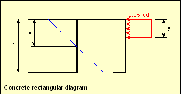
The steel reinforcement stress-strain diagram is taken as bilinear with the horizontal plastic branch:
![]()
The center of gravity of the reinforcement will be placed at a point determined by the mechanical cover defined in each shell vertex.
In the absence of compression reinforcement, the engineering criteria will be taken as the maximum strength of the tensile reinforcement:
![]()
Reinforcement design for flexure follows these steps:
1. Obtaining material strength properties. These properties are obtained from the material properties associated with each shell vertex, which should be previously defined in CivilFEM database.
2. Obtaining shell thickness geometrical data. Shell geometrical data must be defined within the CivilFEM shell structural element.
3. Obtaining reinforcement data. The only data concerning flexure design will be the values for the mechanical cover; these must be defined within the CivilFEM shell structural element.
4. Obtaining internal forces and moments.
5. Calculating the limit bending moment. Depending on the active code, the limit bending moment is calculated as follows:
![]()
Where:
|
b |
Width (one unit length). |
||||||||||||||||||||||
|
d |
Effective depth: d = h – rc |
||||||||||||||||||||||
|
h |
Shell thickness depth. |
||||||||||||||||||||||
|
rt |
Mechanical cover for the tension reinforcement. |
||||||||||||||||||||||
|
rc |
Mechanical cover for the compression reinforcement. |
||||||||||||||||||||||
|
XLim |
Neutral axis depth for the limit bending
moment: |
||||||||||||||||||||||
|
ecu |
Maximum strain of the extreme compression fiber of the concrete. Depends on the selected code (material EPSmin property). |
||||||||||||||||||||||
|
esy |
Elongation for the elastic limit: |
||||||||||||||||||||||
|
β |
Compression depth in the concrete rectangular diagram:
|
6. Calculating the required reinforcement. If the design bending moment (Md) is greater than the limit bending moment, both the tension and compression reinforcements will be designed. Otherwise, only the tension reinforcement will be designed.
Md ≤ Mlim
![]()
From Xn (neutral axis depth), the reinforcements are obtained by:
Tensile reinforcement:
![]()
Compression reinforcement: Asc=0
Md >Mlim
Stress in compression reinforcement is given by:
![]()
Therefore, the resultant reinforcement is:
Tensile reinforcement:

Compression reinforcement:
![]()
7. Obtaining design results. Design results are stored in the CivilFEM results file:
ASTX Reinforcement amount at X top.
ASBX Reinforcement amount at X bottom.
ASTY Reinforcement amount at Y top.
ASBY Reinforcement amount at Y bottom.
Design under Bending Moment and In-Plane Loading:
1. The reinforcement design of shells under bending moment and in plane loading is accomplished by Model Code CEB-FIP 1990.
2. Reinforcements are defined as an orthogonal net (directions of this net are taken as element X and Y axes).
The shell is considered to be divided in three, ideal layers. The outer layers provide resistance to the in-plane effects of both bending and in-plane loading; the inner layer provides for a shear transfer between the outer layers.

From the forces and moments per unit length (mSdx, mSdy, mSdxy, nSdx, nSdy and vSd) that are calculated from the design and obtained from the CivilFEM results file, the following equivalent forces per unit length are obtained:
![]()
![]()
![]()
Where:
|
zx, zy, zv |
Lever arms between the axial forces in the X and Y directions respectively and the shear forces. |
|
y |
Lever arm between the shear forces (Distance from the mean plane of the slab to the selected force). |
Following the Model Code, CivilFEM adopts the values:
![]()
![]()
Where h is the overall thickness of the plate.
So, the former equations change now to:
![]()
![]()
![]()
These parameters are obtained by:
![]()
![]()
They are also represented in the following figure:

Depending on position of the point (ax, ay), the applicable procedure is as follows (If |vSd| » 0, the program utilizes the sign of nSdx and nSdy, to place the point in the correct zone). The internal system providing resistance to in-plane loading may be one of four cases:
CASE I - Tension in reinforcement in two directions and oblique compression in concrete.

CASE II - Tension in reinforcement in Y direction and oblique compression in concrete.

CASE III - Tension in reinforcement in X direction and oblique compression in concrete.

CASE IV - Biaxial compression in the concrete.

According to the case, resistances for the ultimate limit states are the following:
|
Case |
Reinforcements |
Concrete |
|
I |
fytd |
fcd2 |
|
II |
fytd |
fcd2 |
|
III |
fytd |
fcd2 |
|
IV |
fytd |
fcd1 |
Where:
fytd = fytk / gs Design tension strength of steel
fcd2 = 0.60 [1 - fck/250] fcd (MPa)
fcd1 = 0.85 [1 - fck/250] fcd (MPa)
It is assumed that the shell is reinforced with an orthogonal mesh with dimensions of ax and ay.

The angle q is defined between the X-axis and the direction of compression. It can be defined by the user adhering to the condition of 1/3 ³ tan q ³ 3 (By default, q = 45º).
Forces and moments that support a cell of ax x ay dimensions are:
npx = ay . npSdx
npy = ax . npSdy
vpx = ax . vpSd
vpy = ay . vpSd
In general, vpx ¹vpy

1. CASE 1
The method of struts and ties will be applied to the following truss:

Applying the forces equilibrium in node A:

![]()
From the equilibrium of node B, the result is:

![]()
To check if these forces and moments are feasible, the strength of the concrete is checked.
Concrete area:
![]()
Stress on concrete struts:
![]()
This stress is compared to fcd2 to obtain the concrete maximum compression criterion:
![]()
2. CASE II

By equilibrium in node A:

Nh1 cosq + Nh2 cosq = npx
Nh1 sinq - Nh2 sinq = -Vpy
![]()
![]()
By equilibrium in node B:

Na2 = sinq (Nh1+Nh2) + npy
Maximum compression stress on concrete struts:
![]()
This stress is compared to fcd2 to obtain the concrete maximum compression criterion:
![]()
3. CASE III

By equilibrium in node B:
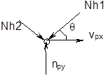
Nh1 cosq - Nh2 cosq = vpx
Nh1 sinq + Nh2 sinq = npy
![]()
![]()
By equilibrium in node A:

Na1 = (Nh1 + Nh2) cos q + npx
The maximum compression stress on concrete struts:
![]()
This stress is compared to fcd2 to obtain the maximum compression of the concrete criterion:
![]()
4. CASE IV – Assuming reinforcing bars are braced
In this situation, the struts and tie model will be the following:
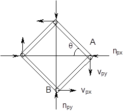
Hyperstatic structure to be separated into
two load states.
Both states have simple solutions due to symmetry.
- Solution of Structure 1:
· Node A:
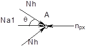
2Nh . cos q + Na1 = npx
· Node B:

2Nh . sin q + Na2 = npy
· Movements compatibility
Where:
Ah = Concrete strut area
Aa1 = Horizontal steel amount
Aa2 = Vertical steel amount
Eh = Concrete modulus of elasticity
Ea = Steel modulus of elasticity
a = Cell width (ax)
b = Cell depth (ay), (b/a = tan q)
![]()
![]()
The length of the concrete struts before deformation:
![]()
![]()
Differentiating this expression:
![]()
However, Da and Db must coincide with the strain of steel bars:
![]()
![]()
DL must coincide with the strain of the concrete struts:
![]()
![]()
![]()
From the obtained equations, the following linear system is created:

Which when solved gives:
![]()
![]()
![]()
- Solution of Structure 2:
Due to non-symmetrical loads, the central bars (steel) are not applicable; therefore, equation 2 is determinant, and the following expression is obtained:

Nh2 sinq + Nh1 sinq = vpy
Nh2 cosq - Nh1 cosq = 0
![]()
Therefore:
![]()
![]()
![]()
Total Actions in Case IV
Adding the actions of 1 and 2:
![]()
![]()
![]()
Where:
![]()
![]()
![]()
With the assumption of braced bars, Na1 and Na2 signs correspond to compression for a + sign and tension for a - sign.
5. CASE IV – Assuming reinforcing bars are not braced
For steel bars without braces, there are two possible determinant truss configurations.
· Case 1
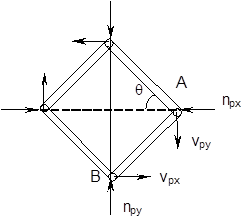
By equilibrium in A node:

Nh1 cosq + Nh2 cosq = npx
Nh1 sinq - Nh2 sinq = vpy
![]()
![]()
By equilibrium in B node:

Na2 = sinq (Nh1+Nh2) - npy > 0
· Case 2

By equilibrium in B node:

Nh1 cosq - Nh2 cosq = vpx
Nh1 sinq + Nh2 sinq = npy
![]()
![]()
By equilibrium in A node:

Na1 = sinq (Nh1 + Nh2) - npx > 0
· Discussion:
With this situation, CivilFEM will select whichever of the two cases satisfies:
Nh1, Nh2 ³ 0 and Na1, Na2 ³ 0
If neither case results in appropriate signs, it will be impossible to equilibrate the force and moment states without bracing the steel bars.
The maximum compression stress on the concrete struts is:
![]()
This stress is compared with fcd1 to obtain the concrete maximum compression criterion:
![]()
For all the cases, steel reinforcement amounts per unit length of the shell are:
![]()
![]()
The checking process described in 6.4.2.5 article of Model Code CEB-FIP1990 will be executed.

The principal shear force is:
![]()
Acting on a surface at an angle f, relative to the Y-axis
![]()
The following check is to performed: V1 £ VRdl
![]()
![]()

Where d is the total depth without the mechanical cover (in mm), and rx, ry are the ratios for the reinforcement closest to the face in tension, in the direction perpendicular to the surface that V1 acts on.
![]() Material properties described in section 9.3.3.
Material properties described in section 9.3.3.
![]() zx, zy, zv and y parameters which are defined
for each element as a fraction of the depth at each point. As previously
stated, CivilFEM uses the specifications from section 6.5.4 of the CEB Model
Code.
zx, zy, zv and y parameters which are defined
for each element as a fraction of the depth at each point. As previously
stated, CivilFEM uses the specifications from section 6.5.4 of the CEB Model
Code.
![]()
![]()
![]() The parameter that indicates whether the bars of
the element are braced.
The parameter that indicates whether the bars of
the element are braced.
![]() Angle q between the reinforcement X axis (element X
axis) and the direction of compression. By default, q = 45º (although any angle
is valid if 1/3 ³ tan q ³ 3).
Angle q between the reinforcement X axis (element X
axis) and the direction of compression. By default, q = 45º (although any angle
is valid if 1/3 ³ tan q ³ 3).
Va1 and Va2 reinforcement amounts per unit length of the shell.
1. The design of reinforcement for bending moments and axial forces is performed independently for each direction.
2. Reinforcements are defined as an orthogonal mesh (directions of this mesh are taken as element X and Y axes).

The axial forces (T*x, T*y) and bending moments (M*x, M*y) used for the design are those obtained for the reinforcement directions as follows:
If torsional moment and membrane shear force are neglected:
T*x = Tx
T*y = Ty
M*x = Mx
M*y = My
If torsional moment (Mxy) and membrane shear force (Txy) are taken into account, then two processes are performed depending on considering membrane (in-plane) shear as tension and as compression.
1) Torsional moment and membrane shear force in tension:
![]()
![]()
![]()
![]()
2) Torsional moment and membrane shear force in compression:
![]()
![]()
![]()
![]()
If only torsional moment (Mxy) is considered:
T*x=Tx
T*y=Ty
![]()
![]()
Where X and Y represent the orthogonal directions of bending reinforcement of the shell.
Reinforcement is designed using one of the following conditions:
Reinforcements design for the Orthogonal Directions method follows these steps:
1) Obtaining material strength properties. These properties are obtained from the material properties associated with each shell structural element, which should be previously defined in CivilFEM model.
2) Obtaining shell vertex geometrical data. Vertex geometrical data must be defined within the CivilFEM model.
3) Obtaining reinforcement data. The only data associated with the bending moment design are the mechanical cover values for the reinforcement; these must be defined within the CivilFEM shell structural elements.
4) Obtaining internal forces and moments. The acting bending moments and axial forces are those obtained for the X and Y directions of each element (T*x, T*y, M*x, M*y).
5) Check and design. Depending on the active code, the checking or design is performed using the pivot diagram described for the checking and design of concrete cross sections.
For checking, the criteria for axial force and bending moment are obtained as for the pivot diagram for beams for each direction.
All reinforcements are considered as scalable for design. The obtained reinforcement factor is therefore the value that must be used to multiply the upper and lower reinforcement amount to fulfill the code requirements.
6) Checking results. Checking results are stored in the CivilFEM results file:
Criterion for X direction.
Criterion for Y direction.
7) Design results. Design results are stored in the CivilFEM results file:
Reinforcement amount for X direction, top surface.
Reinforcement amount for X direction, bottom surface.
Reinforcement amount for Y direction, top surface.
Reinforcement amount for Y direction, bottom surface.
Design criterion for X direction.
Design criterion for Y direction.
Check and Design for Out-of-Plane Shear Loadings according to Eurocode 2 (EN 1992-1-1:2004/AC:2008) and ITER Design Code
Shear check or design according to Eurocode 2 (EN 1992-1-1:2004/AC:2008) and ITER Design Code requires a series of parameters described below:
1) Materials strength properties. These properties are obtained from the material properties associated with each one of the shell vertices and for the active time. Those material properties should be previously defined. The required data are the following:
fck characteristic compressive strength of concrete.
fcd design strength of concrete.
fyk characteristic yield strength of reinforcement.
fywd design strength of reinforcement.
γc partial safety factor for concrete.
γs partial safety factor for reinforcement.
2) Shell vertex geometrical data:
th thickness of the shell vertex (shell structural element).
3) Geometrical parameters. Required data are the following:
c bending reinforcement mechanical cover (shell structural element).
ρ1i ratio of the longitudinal tensile reinforcement per unit length of the shell:
![]()
where:
Ass area of the tensile reinforcement (shell structural element).
q angle of the compressive struts of concrete with the longitudinal axis of the member, (parameter THETA of shell structural element):
![]() Eurocode 2 (EN
1992-1-1:2004/AC:2008)
Eurocode 2 (EN
1992-1-1:2004/AC:2008)
![]() ITER Design Code
ITER Design Code
Mean compressive stress ![]()
Mean
tensile stress ![]()
4) Shell vertex reinforcement data. Required data are the following:
Ass area of reinforcement per unit area, (parameter ASS of shell structural element).
The reinforcement ratio may also be obtained with the following data:
sx, sy spacing of the stirrups in each direction of the shell, (parameters SX and SY of shell structural element).
φ diameter of bars (parameter PHI of shell structural element).
nx, ny number of stirrups per unit length in each direction of the shell (parameters NX and NY of shell structural element).
5) Shell vertex internal forces. The shear force (VEd) acting on the vertex as well as the concomitant axial force (NEd) are obtained from the CivilFEM results file (.RCF).
![]()
which forms an angle with the axis Y
![]()
The value taken
for the design compression force (![]() ) is the
maximum considering all directions:
) is the
maximum considering all directions:
![]()
Design compression force takes into account axial force in x, y directions and in-plane shear using Mohr’s circle stress transformation equations.
The total shear
reinforcement ![]() is computed from those in
each direction, according to equation LL.123 (Annex LL from EN 1992-2:2005):
is computed from those in
each direction, according to equation LL.123 (Annex LL from EN 1992-2:2005):
![]()
Design shear force VEd is compared with the design shear resistance (VRd,c):
![]()
![]()
With the constraints:
![]()
![]()
Where:
|
|
|
|
|
|
|
|
|
|
|
|
|
|
|
|
|
|
|
|
|
|
|
|
|
|
|
|
|
|
||
|
|
|
|
|
|
|
|
If shear reinforcement is defined in the section, VEd must be less than the minimum between the shear reinforcement force:
![]()
and the maximum design shear force resisted without crushing of concrete compressive struts:
Eurocode 2 (EN 1992-1-1:2004/AC:2008):
![]()
ITER Design Code:
![]()
where:

The shear reinforcement must be less than or equal to (Eurocode 2 only):
![]()
Results are written for each end in the CivilFEM results file:
If there is no shear reinforcement defined, the following results can be obtained:
![]()
![]()
![]()
![]()
Tensile strength for the longitudinal reinforcement
![]()
![]() Shear
reinforcement not defined
Shear
reinforcement not defined
![]() Shear
reinforcement defined
Shear
reinforcement defined
![]() Shear
reinforcement not defined
Shear
reinforcement not defined
![]() , Shear
reinforcement defined
, Shear
reinforcement defined
The shear criterion indicates whether the shell vertex is valid for the design forces (if it is less than 1, the vertex satisfies the code provisions; whereas if it exceeds 1, the vertex will not be valid). Furthermore, it includes information about how close the design force is to the ultimate strength. The shear criterion is defined as follows:
|
|
|
|
A value of 2100 for this criterion indicates that VRd,c, VRd,s or VRd,max are null.
First, a check is made to determine if the design shear force VEd is less than or equal to the shear design resistance (VRd,c):
![]()
![]()
with constraints:
![]()
![]()
where:
|
|
= |
|
|
|
|
in MPa |
|
k |
= |
|
|
|
= |
0.15 |
|
|
= |
|
|
|
|
in mm2 |
|
|
|
|
|
𝝂 |
= |
|
![]() =
= ![]()
![]() in N
in N
Results are written for each end in the CivilFEM results file as the following parameters:
|
|
|
|
|
|
|
|
A check is made to ensure that VEd does not exceed the maximum design shear force resisted without crushing of the concrete compressive struts.
Eurocode 2 (EN 1992-1-1:2004/AC:2008):
![]()
ITER Design Code:
![]()
where:

The following results will be saved:
|
|
|
|
|
|
|
|
|
|
If the design shear force is greater than the shear force required to crush the concrete compressive struts, the reinforcement design will not be feasible; as a result, the reinforcement parameter will be defined as 2100.
In this case, the element will be marked as not designed.
The required strength of the reinforcement is given by:
![]()
The amount of reinforcement per length unit is given by:
![]()
The following is also verified (Eurocode 2 only):
![]()
If design shear force is greater than the shear force due to crushing of concrete compressive struts, the reinforcement design will not be feasible; therefore, the parameter containing this datum will be marked with 2100. In this case, the element will be marked as not designed.
ASST and ASSB parameters store the amount of top and bottom reinforcement required due to the additional tensile force DFtd , in the longitudinal reinforcement due to shear VEd.
DFtd=
0,5 VEd (![]() )
)
![]()
ASST= DAsl for negative Bending Moments
ASSB= DAsl for positive Bending Moments
Results are written for each element end in the CivilFEM results file as the parameters:
|
|
|
|
|
|
|
|
|
|
|
|
Check and Design for Out-of-Plane Shear Loadings according to Structural Code (Annex 19)
Shear check or design according to Structural Code (Annex 19) requires a series of parameters described below:
4) Materials strength properties. These properties are obtained from the material properties associated with each one of the shell vertices and for the active time. Those material properties should be previously defined. The required data are the following:
fck characteristic compressive strength of concrete.
fcd design strength of concrete.
fyk characteristic yield strength of reinforcement.
fywd design strength of reinforcement.
γc partial safety factor for concrete.
γs partial safety factor for reinforcement.
5) Shell vertex geometrical data:
th thickness of the shell vertex (shell structural element).
6) Geometrical parameters. Required data are the following:
c bending reinforcement mechanical cover (shell structural element).
ρ1i ratio of the longitudinal tensile reinforcement per unit length of the shell:
![]()
where:
Ass area of the tensile reinforcement (shell structural element).
q angle of the compressive struts of concrete with the longitudinal axis of the member, (parameter THETA of shell structural element):
![]()
4) Shell vertex reinforcement data. Required data are the following:
Ass area of reinforcement per unit area, (parameter ASS of shell structural element).
The reinforcement ratio may also be obtained with the following data:
sx, sy spacing of the stirrups in each direction of the shell, (parameters SX and SY of shell structural element).
φ diameter of bars (parameter PHI of shell structural element).
nx, ny number of stirrups per unit length in each direction of the shell (parameters NX and NY of shell structural element).
5) Shell vertex internal forces. The shear force (VEd) acting on the vertex as well as the concomitant axial force (NEd) are obtained from the CivilFEM results file (.RCF).
![]()
which forms an angle with the axis Y
![]()
The value taken
for the design compression force (![]() ) is the
maximum considering all directions:
) is the
maximum considering all directions:
![]()
Design compression force takes into account axial force in x, y directions and in-plane shear using Mohr’s circle stress transformation equations.
The total shear
reinforcement ![]() is computed from those in
each direction, according:
is computed from those in
each direction, according:
![]()
Design shear force VEd is compared with the design shear resistance (VRd,c):
![]()
![]()
With the constraints:
![]()
![]()
Where:
|
|
|
|
|
|
|
|
|
|
|
|
|
|
|
|
|
|
|
|
|
|
|
|
|
|
|
|
|
|
||
|
|
|
|
|
|
|
|
If shear reinforcement is defined in the section, VEd must be less than the minimum between the shear reinforcement force:
![]()
and the maximum design shear force resisted without crushing of concrete compressive struts:
![]()
where:
The shear reinforcement must be less than or equal to :
![]()
Results are written for each end in the CivilFEM results file:
If there is no shear reinforcement defined, the following results can be obtained:
![]()
![]()
![]()
![]()
Tensile strength for the longitudinal reinforcement
![]()
![]() Shear
reinforcement not defined
Shear
reinforcement not defined
![]() Shear
reinforcement defined
Shear
reinforcement defined
![]() Shear
reinforcement not defined
Shear
reinforcement not defined
![]() , Shear
reinforcement defined
, Shear
reinforcement defined
The shear criterion indicates whether the shell vertex is valid for the design forces (if it is less than 1, the vertex satisfies the code provisions; whereas if it exceeds 1, the vertex will not be valid). Furthermore, it includes information about how close the design force is to the ultimate strength. The shear criterion is defined as follows:
|
|
|
|
A value of 2100 for this criterion indicates that VRd,c, VRd,s or VRd,max are null.
First, a check is made to determine if the design shear force VEd is less than or equal to the shear design resistance (VRd,c):
![]()
![]()
with constraints:
![]()
![]()
where:
|
|
= |
|
|
|
|
in MPa |
|
k |
= |
|
|
|
= |
0.15 |
|
|
= |
|
|
|
|
in mm2 |
|
𝝂 |
= |
|
![]() =
= ![]()
![]() in N
in N
Results are written for each end in the CivilFEM results file as the following parameters:
|
|
|
|
|
|
|
|
A check is made to ensure that VEd does not exceed the maximum design shear force resisted without crushing of the concrete compressive struts.
![]()
where:
The following results will be saved:
|
|
|
|
|
|
|
|
|
|
If the design shear force is greater than the shear force required to crush the concrete compressive struts, the reinforcement design will not be feasible; as a result, the reinforcement parameter will be defined as 2100.
In this case, the element will be marked as not designed.
The required strength of the reinforcement is given by:
![]()
The amount of reinforcement per length unit is given by:
![]()
The following is also verified:
![]()
If design shear force is greater than the shear force due to crushing of concrete compressive struts, the reinforcement design will not be feasible; therefore, the parameter containing this datum will be marked with 2100. In this case, the element will be marked as not designed.
ASST and ASSB parameters store the amount of top and bottom reinforcement required due to the additional tensile force DFtd , in the longitudinal reinforcement due to shear VEd.
DFtd=
0,5 VEd (![]() )
)
![]()
ASST= DAsl for negative Bending Moments
ASSB= DAsl for positive Bending Moments
Results are written for each element end in the CivilFEM results file as the parameters:
|
|
|
|
|
|
|
|
|
|
|
|
Shear checking or design according to ACI 318-05 requires the data described below:
1. Material strength properties. Material properties are assigned to each shell structural element. These material properties must be defined prior to the check and design process. The required properties are:
f’c specified compressive strength of concrete.
fy specified yield strength of reinforcement.
2. Shell vertex data:
th thickness of the shell vertex (shell structural element).
Required properties are:
3. Shell vertex reinforcement data.
c bending reinforcement mechanical cover (shell structural element).
Ass the area of bending reinforcement per unit length. This parameter is used for checking (parameters of shell structural element).
4. Shell vertex shear reinforcement data.
Ass area of shear reinforcement per unit of area. This parameter is used for checking (parameter of shell structural element).
The shear reinforcement ratio may also be obtained from:
AssX, AssY area of shear reinforcement per unit of area in each direction of the shell. (parameters of shell structural element)
sx, sy spacing of the stirrups in each direction of the shell, (parameters of shell structural element).
diameter of bars in mm (shell structural element).
Nx, Ny number of stirrups per unit length in each direction of the shell (parameters of shell structural element).
5. Shell vertex internal forces. The shear force acting on the vertex as well as the concomitant membrane force are obtained from the CivilFEM results file (.RCF). For each direction of the shell vertex:
Force Description
Vu Design out-of-plane shear force
Nu Axial force (positive for compression).
The shear strength provided by concrete (Vc) is calculated with the following expression:
![]()
(ACI 318-05 Eqn:11-3)
where:
bw = 1 (unit length)
![]() square
root of specified compressive strength of concrete, in psi (always taken as
less than 100 psi).
square
root of specified compressive strength of concrete, in psi (always taken as
less than 100 psi).
For sections subject to a compressive axial force,
![]()
(ACI 318-05 Eqn:11-4)
where:
Nu/(th·bw) expressed in psi.
If section is subjected to a tensile force so that the tensile stress is less than 500 psi:
![]()
(ACI 318-05 Eqn:11-8)
If the shell is subjected to a tensile force so that the tensile stress exceeds 500 psi, it is assumed Vc=0.
The calculation result for all elements is stored in the CivilFEM results file as the parameter VC (# is the direction of the shell, X or Y):
VC_# Shear strength provided by concrete.
![]()
The strength provided by the shear reinforcement (Vs) is calculated with the following expression:
![]()
(ACI 318-05 Eqn.11-15)
The calculation result for all elements is stored in the CivilFEM results file as the parameter VS (# is the direction of the shell, X or Y direction):
VS_# Shear strength provided by transverse reinforcement.
![]()
The following condition must be satisfied:
![]()
(ACI 318-01 Eqn.11.5.6.8)
This condition is reflected in the total criterion.
The nominal shear strength (Vn) is the sum of the provided by concrete and by the shear reinforcement:
![]()
This nominal strength, is stored in the CivilFEM results file as the parameter VN (# is the direction of the shell, X or Y):
VN_# Nominal shear strength.
![]()
If reinforcement is required, the minimum allowable value is:
![]()
(ACI 318-05 Eqn.11-13)
The shell vertex will be valid for shear if the following condition is satisfied and if the reinforcement is greater than the minimum required:
![]()
(ACI 318-05 Eqn.11-1 and 11-2)
Where f is strength reduction factor (φ = 0.75 according to chapter 9.3.2.3 of code requirements). Therefore, the shear criterion for the validity of the shell vertex is as follows:
![]()
For each element, this value is stored in the CivilFEM results file as the parameter CRT_#.
If the strength provided by concrete is null and the shear reinforcement is not defined in the shell vertex, and the criterion is equal to 2100.
The φ∙Vn value is stored in CivilFEM results file as the parameter VFI_#.
The total checking criterion is defined as:

The shear strength provided by the concrete (Vc) is calculated by:
![]()
(ACI 318-05 Eqn.11-8)
where:
bw = 1 (unit length)
![]() square
root of specified compressive strength of concrete, in psi (always taken as
less than 100 psi).
square
root of specified compressive strength of concrete, in psi (always taken as
less than 100 psi).
For sections subject to a compressive axial force,
![]()
(ACI 318-05 Eqn.11-4)
where:
Nu/(th·bw) expressed in units of psi.
If the section is subjected to a tensile force such that the tensile stress is less than 500 psi,
![]()
(ACI 318-05 Eqn.11-8)
If the shell is subjected to a tensile force such that the tensile stress exceeds 500 psi, it is assumed that Vc=0.
The calculation result for all element ends is stored in the CivilFEM results file as the parameter VC (# is the direction of the shell, X or Y):
VC_# Shear strength provided by concrete.
![]()
The shell must satisfy the following condition to resist the shear force:
![]()
(ACI 318-05 Eqn.11-1 and 11-2)
where: ![]() is
the strength reduction factor (defined in Environment Configuration).
is
the strength reduction factor (defined in Environment Configuration).
Therefore, the required shear strength of the reinforcement is:
![]()
Calculated results are stored in the CivilFEM results file for both element ends as the parameter VS (# is the direction of the shell, X or Y):
VS_# Shear resistance provided by the transverse reinforcement.
![]()
The following condition must be satisfied:
![]()
(ACI 318-01 Eqn.11.5.6.8)
If the required shear strength of the reinforcement does not satisfy the expression above, the shell vertex cannot be designed; therefore, the reinforcement parameter will be set as 2100.
![]()
In this case, the element will be labeled as not designed.
Once the required shear strength of the reinforcement has been determined, the reinforcement is calculated as the maximum of the following expressions (for both X and Y directions):
![]() for both X and Y directions
for both X and Y directions
(ACI 318-05 Eqn.11-15)
These reinforcement areas will be proportionally increased, if needed, to reach the minimum required ratio:
![]()
(ACI 318-05 Eqn.11-13)
The area of the designed reinforcement per unit length is stored in the CivilFEM results file as:

In this case, the element will be labeled as designed (providing the design process is correct for all element ends).
Shear checking or design according to ACI 318-14 requires the data described below:
1. Material strength properties. Material properties are assigned to each shell structural element. These material properties must be defined prior to the check and design process. The required properties are:
f’c specified compressive strength of concrete.
fy specified yield strength of reinforcement.
![]() modification
factor for lightweight concrete (
modification
factor for lightweight concrete (![]() )
)
2. Shell vertex data:
th thickness of the shell vertex (shell structural element).
Required properties are:
3. Shell vertex reinforcement data.
c bending reinforcement mechanical cover (shell structural element).
Ass the area of bending reinforcement per unit length. This parameter is used for checking (parameters of shell structural element).
4. Shell vertex shear reinforcement data.
Ass area of shear reinforcement per unit of area. This parameter is used for checking (parameter of shell structural element).
The shear reinforcement ratio may also be obtained from:
AssX, AssY area of shear reinforcement per unit of area in each direction of the shell. (parameters of shell structural element)
sx, sy spacing of the stirrups in each direction of the shell, (parameters of shell structural element).
diameter of bars in mm (shell structural element).
Nx, Ny number of stirrups per unit length in each direction of the shell (parameters of shell structural element).
5. Shell vertex internal forces. The shear force acting on the vertex as well as the concomitant membrane force are obtained from the CivilFEM results file (.RCF). For each direction of the shell vertex:
Force Description
Vu Design out-of-plane shear force
Nu Axial force (positive for compression).
The shear strength provided by concrete (Vc) is calculated with the following expression:
![]()
(ACI 318-14 Eqn:11-3)
where:
bw = 1 (unit length)
![]() square
root of specified compressive strength of concrete, in psi (always taken as
less than 100 psi).
square
root of specified compressive strength of concrete, in psi (always taken as
less than 100 psi).
For sections subject to a compressive axial force,
![]()
(ACI 318-14 Eqn:11-4)
where:
Nu/(th·bw) expressed in psi.
If section is subjected to a tensile force so that the tensile stress is less than 500 psi:
![]()
(ACI 318-14 Eqn:11-8)
If the shell is subjected to a tensile force so that the tensile stress exceeds 500 psi, it is assumed Vc=0.
The calculation result for all elements is stored in the CivilFEM results file as the parameter VC (# is the direction of the shell, X or Y):
VC_# Shear strength provided by concrete.
![]()
The strength provided by the shear reinforcement (Vs) is calculated with the following expression:
![]()
(ACI 318-14 Eqn.11-15)
The calculation result for all elements is stored in the CivilFEM results file as the parameter VS (# is the direction of the shell, X or Y direction):
VS_# Shear strength provided by transverse reinforcement.
![]()
The following condition must be satisfied:
![]()
(ACI 318-01 Eqn.11.5.6.8)
This condition is reflected in the total criterion.
The nominal shear strength (Vn) is the sum of the provided by concrete and by the shear reinforcement:
![]()
This nominal strength, is stored in the CivilFEM results file as the parameter VN (# is the direction of the shell, X or Y):
VN_# Nominal shear strength.
![]()
If reinforcement is required, the minimum allowable value is:
![]()
(ACI 318-14 Eqn.11-13)
The shell vertex will be valid for shear if the following condition is satisfied and if the reinforcement is greater than the minimum required:
![]()
(ACI 318-14 Eqn.11-1 and 11-2)
Where f is strength reduction factor (φ = 0.75 according to chapter 21.2 of code requirements). Therefore, the shear criterion for the validity of the shell vertex is as follows:
![]()
For each element, this value is stored in the CivilFEM results file as the parameter CRT_#.
If the strength provided by concrete is null and the shear reinforcement is not defined in the shell vertex, and the criterion is equal to 2100.
The φ∙Vn value is stored in CivilFEM results file as the parameter VFI_#.
The total checking criterion is defined as:
The shear strength provided by the concrete (Vc) is calculated by:
![]()
(ACI 318-14 Eqn.11-8)
where:
bw = 1 (unit length)
![]() square
root of specified compressive strength of concrete, in psi (always taken as
less than 100 psi).
square
root of specified compressive strength of concrete, in psi (always taken as
less than 100 psi).
For sections subject to a compressive axial force,
![]()
(ACI 318-14 Eqn.11-4)
where:
Nu/(th·bw) expressed in units of psi.
If the section is subjected to a tensile force such that the tensile stress is less than 500 psi,
![]()
(ACI 318-14 Eqn.11-8)
If the shell is subjected to a tensile force such that the tensile stress exceeds 500 psi, it is assumed that Vc=0.
The calculation result for all element ends is stored in the CivilFEM results file as the parameter VC (# is the direction of the shell, X or Y):
VC_# Shear strength provided by concrete.
![]()
The shell must satisfy the following condition to resist the shear force:
![]()
(ACI 318-14 Eqn.11-1 and 11-2)
where: ![]() is
the strength reduction factor (defined in Environment Configuration).
is
the strength reduction factor (defined in Environment Configuration).
Therefore, the required shear strength of the reinforcement is:
![]()
Calculated results are stored in the CivilFEM results file for both element ends as the parameter VS (# is the direction of the shell, X or Y):
VS_# Shear resistance provided by the transverse reinforcement.
![]()
The following condition must be satisfied:
![]()
(ACI 318-01 Eqn.11.5.6.8)
If the required shear strength of the reinforcement does not satisfy the expression above, the shell vertex cannot be designed; therefore, the reinforcement parameter will be set as 2100.
![]()
In this case, the element will be labeled as not designed.
Once the required shear strength of the reinforcement has been determined, the reinforcement is calculated as the maximum of the following expressions (for both X and Y directions):
![]()
for both X and Y directions
(ACI 318-14 Eqn.11-15)
These reinforcement areas will be proportionally increased, if needed, to reach the minimum required ratio:
![]()
(ACI 318-14 Eqn.11-13)
The area of the designed reinforcement per unit length is stored in the CivilFEM results file as:
In this case, the element will be labeled as designed (providing the design process is correct for all element ends).
Shear checking or design according to ACI 349-01 requires a series of parameters that are described below. The formulas listed in this section utilize U.S. (British) units: inch (in), pound (lb), and second (s).
1. Material strength properties. Material properties are assigned to each active shell vertex. These material properties must be defined prior to checking and design. The required properties are:
f’c specified compressive strength of concrete.
fy specified yield strength of reinforcement.
2. Shell vertex data:
th thickness of the shell vertex.
Required properties are:
3. Shell vertex reinforcement data.
c bending reinforcement mechanical cover.
Ass the area of bending reinforcement per unit length. This parameter is used for checking (parameters of shell structural element).
4. Shell vertex shear reinforcement data.
Ass area of shear reinforcement per unit of area. This parameter is used for checking (parameters of shell structural element).
The shear reinforcement ratio may also be obtained from:
AssX, AssY area of shear reinforcement per unit of area in each direction of the shell. Parameters of shell structural element.
sx, sy spacing of the stirrups in each direction of the shell, parameters of shell structural element.
diameter of bars in mm.
Nx, Ny number of stirrups per unit length in each direction of the shell.
5. Shell vertex internal forces. The shear force acting on the vertex as well as the concomitant membrane force are obtained from the CivilFEM results file (.RCF). For each direction of the shell vertex:
Force Description
Vu Design out-of-plane shear force
Nu Axial force (positive for compression).
The shear strength provided by concrete (Vc) is calculated by:
![]()
(ACI 349-01 Eqn:11-3)
where:
bw = 1 (unit length)
![]() square
root of specified compressive strength of concrete, in psi (always taken as
less than 100 psi).
square
root of specified compressive strength of concrete, in psi (always taken as
less than 100 psi).
For sections subject to an axial compressive force,
![]()
(ACI 349-01 Eqn:11-4)
where:
Nu/(th·bw) expressed in units of psi.
If the section is subjected to a tensile force such that the tensile stress is less than 500 psi then,
![]()
(ACI 349-01 Eqn:11-8)
If the shell is subjected to a tensile force so that the tensile stress exceeds 500 psi, it is assumed Vc=0.
The calculation result for all elements is stored in the CivilFEM results file as the parameter VC (# is the direction of the shell, X or Y):
VC_# Shear strength provided by concrete.
![]()
The strength provided by shear reinforcement (Vs) is calculated with the following expression:
![]()
(ACI 349-01 Eqn.11-15)
The calculated result for all elements is stored in the CivilFEM results file as the parameter VS (# is the direction of the shell, X or Y):
VS_# Shear strength provided by transverse reinforcement.
![]()
The following condition must be satisfied:
![]()
(ACI 349-01 Eqn.11.5.6.8)
This condition is reflected in the total criterion.
The nominal shear strength (Vn) is the sum of the concrete and shear reinforcement components calculated previously:
![]()
This nominal strength is stored in the CivilFEM results file as the parameter VN (# is the direction of the shell, X or Y):
VN_# Nominal shear strength.
![]()
If reinforcement is required, the minimum allowable value is:

(ACI 349-01 Eqn.11-13)
The shell vertex will be valid for shear if the following condition is satisfied:
![]()
(ACI 349-01 Eqn.11-1 and 11-2)
where f is strength reduction factor (φ = 0.85 according to chapter 9.3.2.3 of code requirements ) and if the reinforcement is greater than the minimum required. Therefore, the validity shear criterion is defined as follows:
![]()
For each element, this value is stored in the CivilFEM results file as the parameter CRT_#.
If the strength provided by concrete is null and the shear reinforcement is not defined in the shell vertex, the criterion is set equal to 2100.
The φ·Vn value is stored in the CivilFEM results file as the parameter VFI_#.
The total checking criterion is defined as:
The shear strength provided by concrete (Vc) is calculated with the following expression:
![]()
(ACI 349-01 Eqn.11-3)
where:
![]() = 1 (unit
length)
= 1 (unit
length)
![]() square
root of specified compressive strength of concrete, in psi (it is always taken
as less than 100 psi).
square
root of specified compressive strength of concrete, in psi (it is always taken
as less than 100 psi).
For sections subject to a compressive axial force,
![]()
(ACI 349-01 Eqn.11-4)
Where:
Nu/(th·bw) is expressed in psi.
If the section is subjected to a tensile force such that the tensile stress is less than 500 psi:
![]()
(ACI 349-01 Eqn.11-8)
If the shell is subjected to a tensile force such that the tensile stress exceeds 500 psi, it is assumed that Vc=0.
The calculation result for all elements is stored in the CivilFEM results file as the parameter VC (# is the direction of the shell, X or Y):
VC_# Shear strength provided by concrete.
![]()
The shell must satisfy the following condition to resist the shear force:
![]()
(ACI 349-01 Eqn.11-1 and 11-2)
Where f is the strength reduction factor (defined in Environment Configuration).
Therefore, the shear force the reinforcement must support is:
![]()
Calculation results are stored in the CivilFEM results file for all elements as the parameter VS (# is the direction of the shell, X or Y):
VS_# Shear resistance provided by the transverse reinforcement.
![]()
The following condition must be satisfied:
![]()
(ACI 349-01 Eqn.11.5.6.8)
If the shear force the reinforcement must support does not satisfy the expression above, the shell vertex cannot be designed, so the parameters where the reinforcement is stored are set to 2100. Then:
![]()
In this case, the element will labeled as not designed.
Once the shear force that the shear reinforcement must support has been obtained, the reinforcement is calculated as follows:

(ACI 349-01 Eqn.11-15)
for each direction X and Y
These reinforcement areas will be increased proportionally, if needed, to reach the minimum required ratio:
![]()
(ACI 349-01 Eqn.11-13)
The area of the designed reinforcement per unit of area is stored in the CivilFEM results file as:
ASSH_X = Shear reinforcement in X direction.
ASSH_Y = Shear reinforcement in Y direction.
ASSH = ASSH_X + ASSH_Y
In this case, the element will be marked as designed (providing the design process is correct for all element directions).
Shear checking or design according to EHE-08 requires the following parameters:
1) Materials strength properties. These properties are obtained from the material properties associated with each one of shell structural element and for the active time. Those material properties should be previously defined. The required data are the following:
fck characteristic compressive strength of concrete.
fyk characteristic yield strength of reinforcement.
fct,m mean tensile strength of concrete.
γc partial safety factor for concrete.
γs partial safety factor for reinforcement.
2) Shell vertex geometrical data:
th thickness of the shell structural element.
3) Geometrical parameters. Required data are the following:
c Bending reinforcement mechanical cover.
ρ1 ratio of the longitudinal tensile reinforcement per unit length of shell:
![]()
where:
Ass the area of the tensile reinforcement.
q angle of the compressive struts of concrete with the longitudinal axis of member.
![]()
4) Shell vertex reinforcement data. Data concerning reinforcements of the shell vertex must be included within CivilFEM database. Required data are the following:
Ass area of reinforcement per unit area.
The reinforcement ratio may also be obtained with:
sx, sy spacing of the stirrups in each direction of the shell.
φ diameter of bars.
nx, ny number of stirrups per unit length in each direction of the shell.
5) Shell vertex internal forces. The shear force acting on the vertex as well as the concomitant axial force are obtained from the CivilFEM results file (.RCF).
Design shear force (Vrd) is obtained from the shear forces in the X and Y directions:
![]()
Which forms an angle with the axis Y:
![]()
The value taken
for the design compression force (![]() ) is the
maximum considering all directions:
) is the
maximum considering all directions:
![]()
Design compression force takes into account axial force in x, y directions and in-plane shear using Mohr’s circle stress transformation equations.
The total shear
reinforcement ![]() is computed from those in
each direction, according to equation LL.123 (Annex LL from EN 1992-2:2005):
is computed from those in
each direction, according to equation LL.123 (Annex LL from EN 1992-2:2005):
![]()
The design shear force (Vrd) is compared to the oblique compression resistance of concrete (Vu1):
![]()
![]()
where:
f1cd design compressive strength of concrete.

K reduction factor by axial forces effect

s’cd effective axial stress in concrete (compression positive) accounting for the axial stress taken by reinforcement in compression.
For each element end, calculation results are written in the CivilFEM results file:
VU1 Ultimate shear strength due to oblique compression of the concrete.
![]()
CRTVU1 Ratio of the design shear (Vrd) to the resistance Vu1.
![]()
The design shear force (Vrd) must be less than or equal to the shear force due to tension in the web (Vu2):
![]()
![]()
Vsu contribution of transverse shear reinforcement in the web to the shear strength.
Vcu contribution of concrete to the shear strength.
Members Without Shear Reinforcement
![]()
![]()
![]()
where:
![]() (Compression positive)
(Compression positive)
![]() < 2, d in mm
< 2, d in mm
![]()
Member With Shear Reinforcement
![]()
Where As/s is the shear reinforcement area per unit length
In this case, the concrete contribution to shear strength is:
![]()
where:
![]() if
if ![]()
![]() if
if ![]()
qe inclination angle of cracks, obtained from:

σxd, σyd design normal stresses, at the center of gravity, parallel to the longitudinal axis of member and to the shear force Vd respectively (tension positive)
Taking ![]()
In addition, the increment in tensile force due to shear force is calculated with the following equation:
![]()
For each end, calculation results are written in the CivilFEM results file:
VSU Contribution of the shear reinforcement to the shear strength.
![]()
VCU Contribution of concrete to the shear strength.
![]()
VU2 Ultimate shear strength by tension in the web.
![]()
CRTVU2 Ratio of the design shear force (Vrd) to the resistance Vu2 .
![]()
If Vu2 = 0, the CTRVU2 criterion is assigned the value of 2100.
The increase in longitudinal reinforcement due to shear is stored in ASST and ASSB parameters (for top and bottom surfaces of the shell respectively).
The shear criterion indicates whether the shell vertex is valid for the design forces (if it is less than 1, the vertex satisfies the code provisions; whereas if it exceeds 1, the vertex will not be valid). Furthermore, it includes information about how close the design force is to the ultimate strength. The shear criterion is defined as follows:
![]()
For each end, this value is stored in the CivilFEM results file as the parameter CRT_TOT.
A value of 2100 for this criterion indicates Vu2 is equal to zero.
The design shear force (Vrd) is compared to the oblique compression resistance of concrete (Vu1):
![]()
![]()
where:
f1cd design compressive strength of concrete

K reduction coefficient by axial force effect
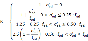
s’cd effective axial stress in concrete (compression positive) accounting for the axial stress taken by the reinforcement in compression.
For each element end, calculation results are written in the CivilFEM results file:
VU1 Ultimate shear strength due to oblique compression of the concrete in web.
![]()
CRTVU1 Ratio of the design shear force (Vrd) to the resistance Vu1.
![]()
If design shear force is greater than shear force that causes the failure by oblique compression of concrete in the web, the reinforcement design is not feasible. Therefore, the reinforcement parameter will be defined as 2100.
![]()
In this case, the element is labeled as not designed.
If there is no failure due to oblique compression, the calculation process continues.
First, a check is made to ensure the design shear force Vd is less than the strength provided by concrete in members without shear reinforcement (Vcu):
![]()
![]()
![]()
Where:
![]() (Compression positive)
(Compression positive)
![]() < 2, d in mm
< 2, d in mm
![]() limited to 60 MPa
limited to 60 MPa
If the shell does not require shear reinforcement, the following parameters are defined:
VCU Contribution of concrete to the shear strength.
![]()
VU2 Ultimate shear strength by tension.
![]()
VSU Contribution of the shear reinforcement to the shear strength.
![]()
ASSH Required amount of shear reinforcement.
![]()
If the shell requires shear reinforcement, sections under shear force will be valid if they satisfy the following condition:
![]()
![]()
Vsu contribution of shear transverse reinforcement in the web to shear strength.
Vcu contribution of concrete to shear strength.
![]()
where:
![]() if
if ![]()
![]() if
if ![]()
qe inclination angle of cracks, obtained from:
σxd, σyd design normal stresses at the gravity center, parallel to the longitudinal axis of the member and to the shear force Vd, respectively (tension positive)
Taking ![]()
Therefore, the shear reinforcement contribution is given by the equation below:
![]()
For each element end, the value of Vcu and Vsu is stored in the CivilFEM results file as the following parameters:
VCU Contribution of concrete to the shear strength.
![]()
VU2 Ultimate shear strength by tension.
![]()
VSU Contribution of the shear reinforcement to the shear strength.
![]()
Once the required shear strength of the reinforcement has been obtained, the reinforcement can be calculated from the equation below:

The area of designed reinforcement per unit of shell area is stored in the CivilFEM results file as the parameter:
![]()
In this case, the element will be labeled as designed (provided the design process is correct for all element shell vertices).
If the design is not possible, the reinforcement will be marked as 2100 and the element will not be designed.
ASST and ASSB parameters store the amount of top and bottom reinforcement required due to the additional tensile force DFtd , in the longitudinal reinforcement due to shear VEd.
![]()

ASST= DAsl for negative Bending Moments
ASSB= DAsl for positive Bending Moments
Shear checking or design according to ACI 349 require the parameters described below. The formulas listed in this section utilize U.S. (British) units: inch (in), pound (lb), and second (s).
1. Material strength properties. This data is obtained from the material properties assigned to each active shell vertex. These material properties must be defined prior to check and design. The required properties are:
f’c specified compressive strength of concrete.
fy specified yield strength of reinforcement.
2. Shell vertex data:
th thickness of the shell vertex.
Required properties are:
3. Shell vertex reinforcement data.
c bending reinforcement mechanical cover.
Ass the area of bending reinforcement per unit length.
4. Shell vertex shear reinforcement data.
AssipX, AssipX area of in plane shear reinforcement per unit of length in each direction of the shell.
5. Shell vertex internal forces. The shear force that acts on the vertex as well as the concomitant membrane force are obtained from the CivilFEM results file (.RCF). For each direction of the shell vertex:
Force Description
Vu Design in plane shear force
Nu Membrane force (positive for compression) perpendicular to Vu
6. Type of check/design. In-plane shear check/design according to ACI 349-01 is divided into the three following types:
· Walls with non-seismic loads. Covers chapter 14 of ACI 349-01 for walls.
· Walls with seismic loads. Covers chapters 14 and 21 of ACI 349-01 for walls.
· Slabs with seismic loads. Covers chapter 21 of ACI 349-01 for slabs.
For sections subjected to an axial compressive force, the shear strength provided by concrete (Vc) is calculated as:
![]()
![]()
(ACI 349-01 11.10.4 and 11.10.5)
Where:
![]() square root of specified
compressive strength of concrete, in psi (always taken less than 100 psi).
square root of specified
compressive strength of concrete, in psi (always taken less than 100 psi).
If the section is subjected to a tensile force such that the tensile stress is less than 500 psi then,
![]()
![]()
(ACI 349-01 11.10.5, 11.3.2.3)
If the shell is subjected to a tensile force such that the tensile stress exceeds 500 psi, it is assumed Vc=0.
The calculation result for all elements is stored in the CivilFEM results file as the parameter VC (# is the direction of the shell, X or Y):
VC_# Shear strength provided by concrete.
![]()
The strength provided by shear reinforcement (Vs) is calculated with the following expression:
![]()
![]()
![]()
(ACI 349-01 11.10.4 Eqn: 11-33)
The calculated result for all elements is stored in the CivilFEM results file as the parameter VS (# is the direction of the shell, X or Y):
VS_# Shear strength provided by reinforcement.
![]()
The nominal shear strength (Vn) is the sum of the concrete and shear reinforcement components calculated previously:
![]()
The shell vertex will be valid for shear if the following conditions are satisfied:
![]()
(ACI 349-01 Eqn: 11-1 and 11-2)
![]()
![]()
(ACI 349-01 11.10.3 and 11.10.4)
![]()
(ACI 349-01 11.10.9.2)
Where f is the strength reduction factor.
The shear criteria are calculated as:
![]()
![]()
![]()
(# is the direction of the shell, X or Y)
Therefore, the validity shear criterion is defined as follows:
![]()
These values are stored for all elements in the CivilFEM results
file as the parameters ![]() and
and ![]() .
.
If the strength provided by concrete is null and the shear reinforcement is not defined in the shell vertex, then Vn=0, and the criterion CRT_1 will be set equal to 2100.
If the shear reinforcement is not defined in the shell vertex, then the criterion CRT_3 is set equal to 2100.
The φ·Vn value is stored in the CivilFEM results file as the parameter VPHI_# (# is the direction of the shell, X or Y).
The nominal shear strength (Vn) is the sum of the concrete and shear reinforcement components:
![]()
But also limited by:
![]()
(ACI 349-01 21.6.5.2)
where Acv is the area of concrete:
![]()
The shell vertex will be valid for shear if the following conditions are satisfied:
![]()
![]()
(ACI 349-01 21.6.5.2)
![]()
![]()
(ACI 349-01 21.6.5.6)
![]()
(ACI 349-01 21.6.2.1)
Where f is the strength reduction factor.
The shear criteria are calculated as:
![]()
![]()
![]()
(# is the direction of the shell, X or Y)
Therefore, the validity shear criterion is defined as follows:
![]()
These values are stored for all elements in the CivilFEM results
file as the parameters ![]() and
and![]() .
.
In case the strength provided by concrete is null and the shear reinforcement is not defined in the shell vertex, then Vn=0, and the criterion CRT_1 is set equal to 2100.
If shear reinforcement is not defined in the shell vertex, then the criterion CRT_3 is set equal to 2100.
The φ·Vn value is stored in the CivilFEM results file as the parameter VPHI_# (# is the direction of the shell, X or Y).
For sections subject to an axial compressive force, the shear strength provided by concrete (Vc) is calculated by:
![]()
![]()
(ACI 349-01 11.10.4 and 11.10.5)
Where:
![]() square
root of specified compressive strength of concrete, in psi (always taken as
less than 100 psi).
square
root of specified compressive strength of concrete, in psi (always taken as
less than 100 psi).
If the section is subjected to a tensile force such that the tensile stress is less than 500 psi:
![]()
![]()
(ACI 349-01 11.10.5, 11.3.2.3)
If the shell is subjected to a tensile force so that the tensile stress exceeds 500 psi, it is assumed Vc=0.
The calculated result for each element is stored in the CivilFEM results file as the parameter VC (# is the direction of the shell, X or Y):
VC_# Shear strength provided by concrete.
![]()
The shell must satisfy the following condition to resist the shear force:
![]()
(ACI 349-01 11-1 and 11-2)
Where f is the strength reduction factor.
Required shear strength of the reinforcement:
![]()
The calculated result for each element is stored in the CivilFEM results file as the parameter VS (# is the direction of the shell, X or Y):
VS_# Shear strength provided by reinforcement.
![]()
The reinforcement amount is obtained by inserting the value of Vs, determined above, into the following equation:
![]()
![]()
![]()
(ACI 349-01 11.10.4 Eqn: 11-33)
The reinforcement amount has a minimum requirement of:
![]()
(ACI 349-01 11.10.9.2)
Therefore:
![]() for each direction X and Y
for each direction X and Y
The area of the designed reinforcement per unit length is stored in the CivilFEM results file as:
![]()
![]()
Also, the following condition must be satisfied:
![]()
![]()
(ACI 349-01 11.10.3 and 11.10.4)
This criterion is calculated as:

(# is the direction of the shell, X or Y)
If CRT_2_# is greater than 1.0, the condition will not be satisfied, and therefore, the element will not be designed. ASSIP_# will be set to 2100 and the element will be labeled as not designed.
The criterion below compares the calculated reinforcement with the minimum reinforcement requirement:
![]()
(# is the direction of the shell, X or Y)
The shell vertex will be valid for shear if the following conditions are satisfied:
![]()
(ACI 349-01 Eqn: 11-1 and 11-2)
With
![]()
![]()
![]()
(ACI 349-01 Eqn: 11-33)
and
![]()
(ACI 349-01 21.6.5.2)
where Acv is the area of concrete:
![]()
Therefore the reinforcement amount is the minimum value that satisfies both expressions:

The reinforcement amount has a minimum requirement of:
![]()
(ACI 349-01 21.6.2.1)
Therefore:
 for each direction X and Y
The area of the designed reinforcement per unit length is stored in the CivilFEM results file as:
![]()
![]()
Also, the following condition must be satisfied:
![]()
![]()
(ACI 349-01 21.6.5.6)
This criterion is calculated as:

(# is the direction of the shell, X or Y)
If CRT_2_# is greater than 1.0, the condition will not be satisfied, and therefore, the element will not be designed. ASSIP_# will then be set to 2100 and the element will be labeled as not designed.
The criterion below compares the calculated reinforcement with the minimum required reinforcement:
![]()
(# is the direction of the shell, X or Y)
The nominal shear strength (Vn) is limited by:
![]()
(ACI 349-01 21.6.5.2)
Where Acv is the area of concrete:
![]()
The shell vertex will be valid for shear if the following conditions are satisfied:
![]()
(ACI 349-01 21.6.5.2)
![]()
![]()
(ACI 349-01 21.6.5.6)
![]()
(ACI 349-01 21.6.2.1, 7.12.2)
Note: A minimum reinforcement amount is not calculated for a thickness greater or equal than 48 in.
Where f is the strength reduction factor.
The shear criteria are calculated as:
![]()
![]()
![]()
![]()
(# is the direction of the shell, X or Y)
Therefore, the validity shear criterion is defined as follows:
![]()
These values are stored for each element in the CivilFEM results
file as the parameters ![]() and
and ![]() .
.
If the strength provided by concrete is null and shear reinforcement is not defined in the shell vertex, then Vn=0, and the criterion CRT_1 is set equal to 2100.
If shear reinforcement is not defined in the shell vertex, then the criterion CRT_3 is set equal to 2100.
The φ·Vn value is stored in the CivilFEM results file as the parameter VPHI_# (# is the direction of the shell, X or Y).
The shell vertex will be valid for shear if the following condition is satisfied:
![]()
(ACI 349-01 21.6.5.2)
where Acv is the area of concrete:
![]()
The reinforcement amount has a minimum requirement of:
![]()
(ACI 349-01 21.6.2.1, 7.12.2)
Note: A minimum reinforcement amount is not calculated for a thickness greater or equal than 48 in.
Therefore the reinforcement amount is the minimum value that satisfies the following expressions for both X and Y directions:


The area of the designed reinforcement per unit length is stored in the CivilFEM results file as:
![]()
![]()
Also, the following condition must be satisfied:
![]()
![]()
(ACI 349-01 21.6.5.6)
This criterion is calculated as:
(# is the direction of the shell, X or Y)
If CRT_2_# is greater than 1.0, the condition above will not be satisfied and therefore the element cannot be designed. ASSIP_# will be set to 2100 and the element will be labeled as not designed.
To determine if a minimum reinforcement amount has been defined, the CRT_3_# criterion is defined as:
![]()
![]()
The cracking check calculates the crack width and checks the following condition:
![]()
where:
![]() Design crack
width.
Design crack
width.
![]() Maximum crack
width (option in the Checking menu)
Maximum crack
width (option in the Checking menu)
The design crack width is obtained from the following expression (Art. 7.3.4):
![]()
![]() Maximum
spacing between cracks.
Maximum
spacing between cracks.
![]() Mean strain in
the reinforcement.
Mean strain in
the reinforcement.
![]() Mean strain in
the concrete between bars.
Mean strain in
the concrete between bars.


f Reinforcement bar size in mm (cross section code property).
![]() Effective
reinforcement ratio, where Ac,eff is the effective area of concrete
in tension, As is the area of reinforcement contained within the
effective concrete area and Ap’ is the area of pre- or post-tensioned
tendons within Ac,eff CivilFEM
calculates this value with
Effective
reinforcement ratio, where Ac,eff is the effective area of concrete
in tension, As is the area of reinforcement contained within the
effective concrete area and Ap’ is the area of pre- or post-tensioned
tendons within Ac,eff CivilFEM
calculates this value with ![]() and
and ![]()
![]() Coefficient
accounting for the influence of the bond properties of the bonded reinforcement
(option in the Checking menu).
Coefficient
accounting for the influence of the bond properties of the bonded reinforcement
(option in the Checking menu).
![]() Coefficient
accounting for the influence of the form of the strain distribution:
Coefficient
accounting for the influence of the form of the strain distribution:
![]()
Where ![]() is the
larger tensile strain and
is the
larger tensile strain and![]() is the
smaller tensile strain at the boundary of a section subjected to eccentric
tension.
is the
smaller tensile strain at the boundary of a section subjected to eccentric
tension.
![]() Constants defined
in the National Annexes (option in the Checking menu).
Constants defined
in the National Annexes (option in the Checking menu).
c Cover to the longitudinal reinforcement. (Cross section code property).
![]() Stress in the
tensile reinforcement calculated for a cracked section.
Stress in the
tensile reinforcement calculated for a cracked section.
![]() Elastic
modulus of the longitudinal reinforcement.
Elastic
modulus of the longitudinal reinforcement.
![]() Coefficient
accounting for the influence of the duration of the loading (option in the
Checking menu).
Coefficient
accounting for the influence of the duration of the loading (option in the
Checking menu).
![]() Ratio between
steel-concrete elastic modulus (Es/Ecm).
Ratio between
steel-concrete elastic modulus (Es/Ecm).
During the calculation process, it is necessary to determine the reinforcement stress under service loads (σs) with the assumption the section is cracked.
The calculation of these stresses is an iterative process in which CivilFEM searches for the deformation plane that causes a stress state that is in equilibrium with the external loads. The reinforcement stress is obtained from this deformation plane and from the reinforcement position.
The design loads are taken as external loads for the case of serviceability stress calculation. For the stress calculation at the instant the crack appears, the external loads are taken as homothetic to the design loads that cause a stress equivalent to the concrete tensile strength in the fiber under the greatest amount of tension.
If the loads acting on the cross section cause collapse under axial plus bending checking, the cross section and the associated element are labeled as non-checked.
Checking results are stored in the corresponding CivilFEM result file.
The following results are available:
|
CRT_TOT_X |
Cracking criterion. |
||||||
|
SIGMA_X |
Maximum tensile stress. |
||||||
|
WK_X |
Design crack width |
||||||
|
SRMAX_X |
Maximum spacing between cracks. |
||||||
|
EM_X |
Difference between the mean strain in the
reinforcement and the mean strain in concrete |
||||||
|
POS_X |
Cracking position inside the section
|
||||||
|
|
|
||||||
|
CRT_TOT_Y |
Cracking criterion. |
||||||
|
SIGMA_Y |
Maximum tensile stress. |
||||||
|
WK_Y |
Design crack width |
||||||
|
SRMAX_Y |
Maximum spacing between cracks. |
||||||
|
EM_Y |
Difference between the mean strain in the
reinforcement and the mean strain in concrete |
||||||
|
POS_Y |
Cracking position inside the section.
|
||||||
|
|
|
For the cracking check (wmax > 0) the total criterion is defined as:
![]()
For decompression checking (wmax = 0) the total criterion is defined as:
![]()
where
![]() concrete
design compressive strength
concrete
design compressive strength
![]() Maximum section
stress (positive tension). It corresponds to the SIGMA result. (If CRT_TOT is
negative, it’s taken as zero)
Maximum section
stress (positive tension). It corresponds to the SIGMA result. (If CRT_TOT is
negative, it’s taken as zero)
Therefore, values for the total criterion larger than one indicate that the section does not pass as valid for this code.
The cracking check calculates the crack width and checks the following condition:
![]()
where:
![]() Design crack
width.
Design crack
width.
![]() Maximum crack
width (option in the Checking menu)
Maximum crack
width (option in the Checking menu)
The design crack width is obtained from the following expression (Art. 7.3.4):
![]()
![]() Maximum
spacing between cracks.
Maximum
spacing between cracks.
![]() Mean strain in
the reinforcement.
Mean strain in
the reinforcement.
![]() Mean strain in
the concrete between bars.
Mean strain in
the concrete between bars.
f Reinforcement bar size in mm (cross section code property).
![]() Effective
reinforcement ratio, where Ac,eff is the effective area of concrete
in tension, As is the area of reinforcement contained within the
effective concrete area and Ap’ is the area of pre- or
post-tensioned tendons within Ac,eff CivilFEM calculates this value with
Effective
reinforcement ratio, where Ac,eff is the effective area of concrete
in tension, As is the area of reinforcement contained within the
effective concrete area and Ap’ is the area of pre- or
post-tensioned tendons within Ac,eff CivilFEM calculates this value with ![]() and
and ![]()
![]() Coefficient
accounting for the influence of the bond properties of the bonded reinforcement
(option in the Checking menu).
Coefficient
accounting for the influence of the bond properties of the bonded reinforcement
(option in the Checking menu).
![]() Coefficient
accounting for the influence of the form of the strain distribution:
Coefficient
accounting for the influence of the form of the strain distribution:
![]()
Where ![]() is the
larger tensile strain and
is the
larger tensile strain and![]() is the
smaller tensile strain at the boundary of a section subjected to eccentric
tension.
is the
smaller tensile strain at the boundary of a section subjected to eccentric
tension.
![]() Constants defined
in the National Annexes (option in the Checking menu).
Constants defined
in the National Annexes (option in the Checking menu).
c Cover to the longitudinal reinforcement. (Cross section code property).
![]() Stress in the
tensile reinforcement calculated for a cracked section.
Stress in the
tensile reinforcement calculated for a cracked section.
![]() Elastic
modulus of the longitudinal reinforcement.
Elastic
modulus of the longitudinal reinforcement.
![]() Coefficient
accounting for the influence of the duration of the loading (option in the
Checking menu).
Coefficient
accounting for the influence of the duration of the loading (option in the
Checking menu).
![]() Ratio between
steel-concrete elastic modulus (Es/Ecm).
Ratio between
steel-concrete elastic modulus (Es/Ecm).
During the calculation process, it is necessary to determine the reinforcement stress under service loads (σs) with the assumption the section is cracked.
The calculation of these stresses is an iterative process in which CivilFEM searches for the deformation plane that causes a stress state that is in equilibrium with the external loads. The reinforcement stress is obtained from this deformation plane and from the reinforcement position.
The design loads are taken as external loads for the case of serviceability stress calculation. For the stress calculation at the instant the crack appears, the external loads are taken as homothetic to the design loads that cause a stress equivalent to the concrete tensile strength in the fiber under the greatest amount of tension.
If the loads acting on the cross section cause collapse under axial plus bending checking, the cross section and the associated element are labeled as non-checked.
Checking results are stored in the corresponding CivilFEM result file.
The following results are available:
|
CRT_TOT_X |
Cracking criterion. |
||||||
|
SIGMA_X |
Maximum tensile stress. |
||||||
|
WK_X |
Design crack width |
||||||
|
SRMAX_X |
Maximum spacing between cracks. |
||||||
|
EM_X |
Difference between the mean strain in the
reinforcement and the mean strain in concrete |
||||||
|
POS_X |
Cracking position inside the section
|
||||||
|
|
|
||||||
|
CRT_TOT_Y |
Cracking criterion. |
||||||
|
SIGMA_Y |
Maximum tensile stress. |
||||||
|
WK_Y |
Design crack width |
||||||
|
SRMAX_Y |
Maximum spacing between cracks. |
||||||
|
EM_Y |
Difference between the mean strain in the
reinforcement and the mean strain in concrete |
||||||
|
POS_Y |
Cracking position inside the section.
|
||||||
|
|
|
For the cracking check (wmax > 0) the total criterion is defined as:
![]()
For decompression checking (wmax = 0) the total criterion is defined as:
![]()
where
![]() concrete
design compressive strength
concrete
design compressive strength
![]() Maximum section
stress (positive tension). It corresponds to the SIGMA result. (If CRT_TOT is
negative, it’s taken as zero)
Maximum section
stress (positive tension). It corresponds to the SIGMA result. (If CRT_TOT is
negative, it’s taken as zero)
Therefore, values for the total criterion larger than one indicate that the section does not pass as valid for this code.
Checking of the Cracking Limit State according to ACI 318-05 and ACI 318-14 consists of the following condition:
![]()
Where:
![]() Reinforcement
spacing closest to the fiber in tension (option in the Checking menu)
Reinforcement
spacing closest to the fiber in tension (option in the Checking menu)
S Design reinforcement spacing
CivilFEM checks this condition by applying the general calculation method for the reinforcement spacing (Art. 10.6.4):
![]()
![]()
where:
![]() Calculated
stress in reinforcement at service loads (in ksi).
Calculated
stress in reinforcement at service loads (in ksi).
![]() Geometrical
cover (cross section code property) (in inches).
Geometrical
cover (cross section code property) (in inches).
During the calculation process, it’s necessary to determine the reinforcement stress under service loads (fs).
The calculation of the stresses is an iterative process in which the program searches for the deformation plane that causes a stress state that is in equilibrium with the external loads. The reinforcement stress is obtained from this deformation plane and from the reinforcement position.
The design loads are taken as external loads.
If the loads acting on the cross section cause collapse under axial plus bending checking, the cross section and the element to which it belongs are marked as non checked.
Checking results are stored in the corresponding CivilFEM results file.
The following results are available:
|
CRT_TOT_X |
Cracking criterion in X direction. |
|||||||
|
S_X |
Design reinforcement spacing in X direction. |
|||||||
|
FS_X |
Reinforcement stress in X direction. |
|||||||
|
SIGMA_X |
Maximum tensile stress in X direction. |
|||||||
|
POS_X |
Cracking position inside the section in X direction.
|
|||||||
|
CRT_TOT_Y |
Cracking criterion in Y direction. |
|||||||
|
S_Y |
Design reinforcement spacing in Y direction. |
|||||||
|
FS_Y |
Reinforcement stress in Y direction. |
|||||||
|
SIGMA_Y |
Maximum tensile stress in Y direction. |
|||||||
|
POS_Y |
Cracking position inside the section in Y direction.
|
|||||||
For the cracking check (sd > 0) the total criterion is defined as:
![]()
For decompression checking (sd = 0) the total criterion is defined as:
![]()
where
![]() concrete
design compressive strength.
concrete
design compressive strength.
![]() Maximum section
stress (positive tension), corresponding to the SIGMA result. (If CRT_TOT is
negative, it is taken as zero)
Maximum section
stress (positive tension), corresponding to the SIGMA result. (If CRT_TOT is
negative, it is taken as zero)
Therefore, the values for the total criterion larger than one indicate that the section is not considered valid for this code.
Checking and reinforcement designing of reinforced concrete beams in CivilFEM is available for structures formed by 2D and 3D beam elements under axial loading plus biaxial bending, axial loading plus bending (particular case), shear, torsion and combined shear and torsion.
The check and design process of reinforced concrete beams under axial loading plus biaxial bending is based on the 3D interaction diagram of the analysed transverse section. This 3D interaction diagram contains forces and moments (FX, MY, MZ) corresponding to the sections ultimate strength states. Using this diagram, the program is able to check and design the section accounting for forces and moments previously obtained that act on the section. This process considers both generic sections and sections formed by different concretes and reinforcement steels.
The codes CivilFEM considers for the checking and design of reinforced beams subjected to axial force and biaxial bending are: ACI 318, EHE, Eurocode 2, ITER Design code, British Standard 8110, Australian Standard 3600, CEB-FIP 1990 model code, the Chinese code GB50010, NBR6118, AASHTO Standard Specifications for Highway Bridges, Russian Code СП 52-101-03, Indian Standard IS 456 and ACI 349.
The interaction diagram is a graphical summary that contains the forces and moments (FX, MY) or (FX, MZ) corresponding to the section ultimate strength states. In CivilFEM the ultimate strength states are determined through the pivots diagram.
The “Pivot” concept is related to the limit behavior of the cross section with respect to steel and concrete material characteristics.
A pivot is a strain limit associated with a material and its position in the section. If the strain in a section’s pivot exceeds the limit for that pivot, the section will be considered as cracked. Thus, pivots establish the positions of the strain plane. In an ultimate strength state, the strain plane supports at least one pivot of the section.
In CivilFEM, pivots are defined as material properties and these properties (pivots) are extrapolated to all the section’s points, taken into account the material of each point. Therefore, for the section’s strain plane determination, the following pivots and their corresponding material properties will be considered:
|
A Pivot |
EPSmax. Maximum allowable strain in tension at any point of the section (largest value of the maximum strains allowable for each point of the section if there are different materials in the section). |
|
B Pivot |
EPSmin. Maximum allowable strain in compression at any point of the section (largest value of the maximum strains allowable for each point of the section). |
|
C Pivot |
EPSint. Maximum allowable strain in compression at the interior points of the section. |
Navier’s hypothesis is assumed for the determination of the strains plane. The strain’s plane is determined according to the following equation:
![]()
where:
|
e (y,z) |
Strain of a section point as a function of the Y, Z axes of the section. |
|
|
Strain in the origin of the section (center of gravity). |
|
|
Curvature in Z axis. |
|
|
Curvature in Y axis. |
In CivilFEM, the three elements eg, Kz, Ky are substituted by the elements ![]() ,
, ![]() , K to determine the
strain plane. The relationship between (Kz, Ky) and (q, K) is the following:
, K to determine the
strain plane. The relationship between (Kz, Ky) and (q, K) is the following:
![]() =
K·cos(q)
=
K·cos(q)
![]() =
K·sin(q)
=
K·sin(q)
q = Angle of the neutral axis with respect to the section’s Y axis

As stated in the previous section, CivilFEM
uses the elements ![]() to determine the
strains plane (ultimate strength plane) of the section.
to determine the
strains plane (ultimate strength plane) of the section.
![]() and q are used as
independent variables. The process is composed of the following steps:
and q are used as
independent variables. The process is composed of the following steps:
1.
Values of ![]() and q are chosen
arbitrarily inside the extreme values allowed for these variables, which are:
and q are chosen
arbitrarily inside the extreme values allowed for these variables, which are:
EPSmin
(B pivot ) ![]() EPSmax (A pivot)
EPSmax (A pivot)
-180º < q < +180º
If there is no A pivot, (if there is no reinforcement steel or if ACI, AS3600 or BS8110 codes are used) the tension limit does not exist and is considered infinite.
2. From the angle q, the program can identify which points are inside and outside the nucleus of the section.
3. Once the interior and exterior points are known, the two extreme admissible strains, EPSmin and EPSmax, are defined in each of the points (for each point based on its material).
4. For each point of the section, the minimum ultimate strength curvature (K) is calculated.
5. The K curvature will be adopted as the minimum of all the curvatures of all the section points, according to the condition K ³ 0.
6. From the obtained K curvature and eg (strain imposed in the section’s center of gravity), the deformation corresponding to each of the section points e (x, y), is determined using the equations shown previously.
7. From the e (x, y) strain, the stress corresponding to each point of the section (sp) is calculated and entered into the stress-strain diagram for that point. Through this method, the stress distribution inside the section is determined.

8.
Thus, as the elements![]() are determined, the
ultimate forces and moments (FX, MY, MZ) corresponding to the eg strain and the q angle defined in step 1 are obtained by the summation of stresses
at each of the section’s points multiplied by its corresponding weight.
are determined, the
ultimate forces and moments (FX, MY, MZ) corresponding to the eg strain and the q angle defined in step 1 are obtained by the summation of stresses
at each of the section’s points multiplied by its corresponding weight.


Where: NP = number of points of the section
![]() ,
, ![]() ,
, ![]() = weights at each
point of the section.
= weights at each
point of the section.
Note: For the design process, two components of forces and moments will be calculated: the component relating to the fixed points (corresponding to the reinforcement defined as fixed and to the concrete) and the component relating to the scalable points (corresponding to the part of the section reinforcement defined as scalable, see Chapter 4.6.). The final forces and moments will be equal to the sum of the forces and moments of both components. The forces and moments due to the component for scalable points will be multiplied by the reinforcement factor (w).
(FX, MY, MZ)real = (FX, MY, MZ)fixed + w.(FX, MY, MZ)scalable
9. Steps 1 to 8 are repeated, adjusting the eg and q values and calculating the corresponding ultimate force and moments (FX, MY, MZ). Each defined couple (eg and q) represents a point in the 3D interaction diagram of the section. The greater the number of eg and q values used (inside the interval specified in step 1), the larger of the number of points in the diagram, and therefore the accuracy of the diagram will increase.
With all of the 2D points previously obtained, the program constructs the interaction diagram by calculating the convex hull of these points. Once the convex hull is calculated, the “convexity criterion” of the diagram is determined; this criterion is the minimum of the criteria calculated for all the points of the diagram. The ideal value of the convexity criterion of the diagram is 1. In CivilFEM, it is not recommended to perform the check and design described above with interaction diagrams whose convexity criterion is less than 0.95.
It has been proven that the interaction diagram of sections composed by materials whose stress-strain law (for sections analysis) presents a descending branch has a very low convexity criterion. The check and design process with the diagram of these sections may lead to unsafe solutions. Therefore, it is NOT RECOMMENDED to use materials with this characteristic.
Normal interaction diagrams contain the coordinates’ origin in their interior, but in some cases the origin may be a point belonging to the surface or even a point outside the diagram (such as for prestressed concrete sections). In this situation, the section is cracked for null forces and moments.
To avoid these situations, CivilFEM changes the axes, placing the origin of the coordinate system inside the geometric center of the diagram. In this case, the calculation of the safety criterion is executed according to the new coordinate’s origin instead of the real origin.
If these changes are not made, safety forces and moments (in the diagram interior) could have a safety factor less than 1.00 and vice versa. If the coordinate’s origin is close to the diagram’s surface (although still inside), it will also be necessary to change the origin coordinates. In these cases, although the safety factors maintain values greater than 1.0 for safe sections and less than 1.0 for unsafe ones, they may adopt arbitrary values not very related to the section’s real safety factor.
Therefore, CivilFEM establishes a criterion to determine whether to use the real coordinate system origin or a modified one as a reference. Thus, if the following condition is fulfilled, the origin of the coordinates will be modified, moving the diagram’s real center to its geometric center.
![]()
Where:
|
Distance |
Minimum distance from any point of the diagram to the real coordinate system origin. |
|
Delta |
Variable parameter which may be defined inside the [0,1] range. By default Delta=0.05. |
|
Diameter |
Diagonal of the rectangle which involves the diagram surface points. |
- The selection of the strains values at the origin of the section (eg) inside the interval (EPSmin, EPSmax) for each adopted angle of the neutral axis (q) is made uniformly spaced for sections with reinforcements below the center of gravity (bottom reinforcement). Half of it is distributed in the tension zone and the other half in the compression zone, avoiding a concentration of points in the ultimate tension zone and obtaining an even distribution of points.
- If the section does not have bottom reinforcement for each q or the reinforcement does not have pivot (EPSmax) (as in the case of the ACI or BS8110 codes), the distribution of the tension zone is hyperbolic. The compression zone will continue to have uniform distribution. By default the number of the values adopted by eg is 30. The number of values must be a multiple of 2.
- At the same time, the selection of the q values is also uniform, inside the interval (-180º, +180º). The number of values must be a multiple of 4 in order to embrace the 4 quadrants of the section. By default, the number of values adopted by the program is 28.
- Although the number of the values of eg and q used for the construction of the diagram can be defined by the user, it is recommended to choose numbers close to the default values. These values have been chosen in consideration of the calculation time and precision. If a number of values for either variable is a great deal higher than the default value, the processing time increases significantly.
On the other hand, if the number of values of eg and q is reduced significantly, the precision in the calculation of the diagram may be affected.

![]() This checking procedure only verifies the
section’s strength requirements; thus, requirements relating to serviceability
conditions, minimum reinforcement amounts or reinforcement distribution for
each code and structural typology will be not
be considered.
This checking procedure only verifies the
section’s strength requirements; thus, requirements relating to serviceability
conditions, minimum reinforcement amounts or reinforcement distribution for
each code and structural typology will be not
be considered.
![]() Navier’s hypothesis is always assumed as valid;
therefore, the deformed section will remain plane. The longitudinal strain of
concrete and steel will be proportional to the distance from the neutral axis.
Navier’s hypothesis is always assumed as valid;
therefore, the deformed section will remain plane. The longitudinal strain of
concrete and steel will be proportional to the distance from the neutral axis.
Checking elements for axial force and biaxial bending adheres to the following steps:
1. Obtaining the acting forces and moments of the section (FXd, MYd, MZd). The acting forces and moments are obtained, following a calculation, directly from the CivilFEM results file (file .RCF).
2. Constructing the interaction diagram of the section. The ultimate strain state is determined such that the ultimate forces and moments are homothetic to the acting forces and moments with respect to the diagram center.
Obtaining the strength criterion of the section. This criterion is defined as the ratio between two distances. As shown above, the distance to the “center” of the diagram (point A of the figure) from the point representing the acting forces and moments (point P of the figure) is labeled as d1 and the distance to the center from the point representing the homothetic ultimate forces and moments (point B) is d2.
![]()
If this criterion is less than 1.00, the forces and moments acting on the section will be inferior to its ultimate strength, and the section will be safe. On the contrary, for criterion larger than 1.00, the section will not be considered as valid.
![]() Total Criterion,
if this criterion is less than 1.0, in such a way that the forces
and moments acting on the section are inferior to its ultimate strength, the
section is safe (element is OK). On the contrary, for criterion higher than
1.0, the section will be considered as not valid (element is NOT OK).
Total Criterion,
if this criterion is less than 1.0, in such a way that the forces
and moments acting on the section are inferior to its ultimate strength, the
section is safe (element is OK). On the contrary, for criterion higher than
1.0, the section will be considered as not valid (element is NOT OK).


![]() Interaction Diagram, it includes all the necessary information for checking as well as
design. Effects of actions, ultimate strength, safety information, as well as
strength with and without reinforcement can be seen. The criterion provided is
the ratio between the distances of the center of the diagram to the design
loads point and the center of the diagram to the ultimate strength.
Interaction Diagram, it includes all the necessary information for checking as well as
design. Effects of actions, ultimate strength, safety information, as well as
strength with and without reinforcement can be seen. The criterion provided is
the ratio between the distances of the center of the diagram to the design
loads point and the center of the diagram to the ultimate strength.

For the design of sections under axial loading and biaxial bending, the same hypothesis for the axial load and biaxial bending check is adopted.
For the design, an optimization process is carried out through successive iterations; within this process, the safety factor of the section (or its criterion) must be strict (»1.00). These values are determined by the following steps:
1. Obtaining the minimum and maximum reinforcement factors. The maximum and minimum reinforcement factors (wmax ,wmin) are introduced by the user. The designed reinforcement of the section will always be more than wmin times and less than wmax times the initial distribution.
2. Obtaining the reinforcement data of the section. The reinforcements of the section to be designed must be defined by the class (only reinforcements defined as scalable are modified), type, position and initial amount (see Chapter 4.4). The designed reinforcement will be homothetic to the one defined in the section, in such a way that it complies with the strength requirements of the section. If the reinforcement amount is null, the program will not perform the design.
3.
Obtaining the forces and moments acting on
the section. Forces and moments (![]() ) acting on the
section are obtained directly from the CivilFEM results file (file .RCF).
) acting on the
section are obtained directly from the CivilFEM results file (file .RCF).
4. Constructing the 2D interaction diagram. The diagram of the section is constructed for reinforcement corresponding to wmin times the initial distribution to determine the ultimate forces and moments of the section with this configuration.
![]()
5. From the interaction diagram of the previous step the ultimate strain state homothetic to the acting forces and moments can be determined with respect to the diagram center.
6. Obtaining the strength criterion of the section. This criterion is determined following the same process as described in the checking section.
7.
If the value of the criterion is less than
1.00 (the forces and moments acting on the section are inferior to its ultimate
strength), the section will be assigned reinforcement equal to ![]() times the initial distribution and the calculation will be terminated.
times the initial distribution and the calculation will be terminated.
8.
Repetition of steps 4, 5 and 6 for a
reinforcement corresponding to ![]() times the initial
reinforcement distribution.
times the initial
reinforcement distribution.
![]()
9. If the value of the strength criterion of the section is more than 1.00 (acting forces are larger than the ultimate strength of the section), the program will indicate it is not possible to design the section and will not assign reinforcement nor will it continue calculating.
10. Optimization of the section reinforcement through successive iterations. From the forces and moments previously determined (FX, MY, MZ)fixed and (FX, MY, MZ)scalable, a search is done to obtain a reinforcement factor w that will produce a value of the section criterion between 0.99 and 1.01. The program will then assign reinforcement equal to w times the initial distribution of the section.
CivilFEM can obtain the needed reinforcement (design) in order to fulfill the code requirements. CivilFEM uses the interaction diagram of each section, taking into account the design stress-strain curve for each of the materials of the section. Moments in two directions are applied to the section. Scalable reinforcement will be increased/decreased until the section reaches a safety factor of 1.0 according to the code.
![]() Design Total Criterion, elements with values
equal to unity means that those elements were designed and a reinforcement
factor was found within the provided range of ωmin and ωmax.
Design Total Criterion, elements with values
equal to unity means that those elements were designed and a reinforcement
factor was found within the provided range of ωmin and ωmax.
Designed elements


If the result is out of range then 2100 values will appear.
Not Designed elements
![]()

![]() Reinforcement factor, depending on the range of
ωmin and ωmax provided, different results
appear:
Reinforcement factor, depending on the range of
ωmin and ωmax provided, different results
appear:
1) Obtained reinforcement factor is inside (ωmin ,ωmax),
then REINFACT value times the defined reinforcement amount gives the needed
reinforcement.
2) ωmax is smaller than the reinforcement factor
obtained, then REINFACT = 2100 for those elements.
3) ωmin is greater than the reinforcement factor
obtained, then REINFACT = ωmin for those elements.


If CivilFEM is not able to design reinforcement with considered section, materials and initial reinforcement amount, then 2100 values will appear.
![]() Total scalable reinforcement (SCALAREA): This
option gives the the product of the REINFACT previously obtained and the total scalable
area of all reinforcement groups defined as scalable:
Total scalable reinforcement (SCALAREA): This
option gives the the product of the REINFACT previously obtained and the total scalable
area of all reinforcement groups defined as scalable:
![]()
The user should note that reinforcement defined as Fixed will not be included in the calculation. If REINFACT is 2100 , SCALAREA will also be assigned the value 2100 .
For the check and design of reinforced concrete beams with different codes, the only variation will be the consideration of the pivots relative to the concrete (corresponding to EPSmin) and to the steel (corresponding to EPSmax). Therefore the pivots diagram for each code will differ in the construction of the section interaction diagram.
Codes provided by CivilFEM for the check and design of reinforced concrete beams under axial load and biaxial bending include: Eurocode 2, ITER Design code, Spanish code EHE, American codes ACI 318 and ACI 349, British Standard 8110, Australian Standard 3600, CEB-FIP model code, Chinese code GB50010, Brazilian code NBR6118, AASHTO Standard Specifications for Highway Bridges and ITER Structural Design Code for Buildings.
The strain limits defined hereafter are default values, but can be changed for each of the materials defined in the model.
If the active code is Eurocode 2 ,ITER Structural Design Code for Buildings or Structural Code (Spanish code), the strain states relative to concrete and reinforcement steel are those defined in the following figure:

If concrete has ![]() , the concrete strain
limits are the following:
, the concrete strain
limits are the following:
EPSmin (‰) = ![]()
EPSint (‰) = ![]()
If the active code is EHE, the strain states relative to concrete and reinforcement steel are those defined in the following figure:

If concrete has fck > 50 MPa, the concrete strain limits are the following:
EPSmin (‰) = ![]()
EPSint
(‰) = ![]() .
.
If the active code is ACI 318-05, the strain states relative to concrete and reinforcement steel are those defined in the following figure. It can be noted that there is no pivot relative to steel (EPSmax), considering the section does not fail due to reinforcement steel deformation.

The theoretical values of the interaction
diagram are affected by the strength reduction factor f according to Chapter 9.3
of Building Code Requirements for Structural Concrete Structures (ACI
318-05) document:

![]()
![]()
![]()
![]()
![]()
Where et is the maximum strain obtained at the reinforcement and ![]() is the strength reduction
factor for compression controlled sections:
is the strength reduction
factor for compression controlled sections:
For ACI 318-05 (according to chapter 9.3.2 from code requirements)
![]() Member with spiral reinforcement
Member with spiral reinforcement ![]() =0.70
=0.70
![]() Other reinforcement members
Other reinforcement members ![]() =0.65 (default value)
=0.65 (default value)
Furthermore, according to Chapter 10.3.6 of Building Code Requirements for Structural Concrete Structures (ACI 318-05) document, design axial strength φPn of compression members must not be greater than:
1.
For member with spiral reinforcement:
![]()
2.
For other reinforcement:
![]()
Where Ag is the gross area of concrete section and Ast is the total area of longitudinal reinforcement.
If the active code is ACI 318-14, the strain states relative to concrete and reinforcement steel are those defined in the following figure. It can be noted that there is no pivot relative to steel (EPSmax), considering the section does not fail due to reinforcement steel deformation.

The theoretical values of the interaction diagram are affected by the strength reduction factor f according to Chapter 21.2.2 of Building Code Requirements for Structural Concrete Structures (ACI 318-14) document

![]()
![]()
![]()
![]()
![]()
Where et is the maximum strain obtained at the reinforcement and ![]() is the strength reduction
factor for compression controlled sections:
is the strength reduction
factor for compression controlled sections:
For ACI 318-14 (according to chapter 21.2.2 from code requirements)
![]() Member with spiral reinforcement
Member with spiral reinforcement ![]() =0.75
=0.75
![]() Other reinforcement members
Other reinforcement members ![]() =0.65 (default value)
=0.65 (default value)
Furthermore, according to Chapter 22.4.2 of Building Code Requirements for Structural Concrete Structures (ACI 318-14) document, design axial strength φPn of compression members must not be greater than:
1.
For member with spiral reinforcement:
![]()
2.
For other reinforcement:
![]()
Where Ag is the gross area of concrete section and Ast is the total area of longitudinal reinforcement.
If the active code is ACI 349-01, the strain states relative to concrete and reinforcement steel are the ones defined in the following figure. It can be noted that there is no pivot relative to steel (EPSmax), considering the section does not fail due to reinforcement steel deformation.

The theoretical values of the interaction diagram are affected by the strength reduction factor f according to Chapter 9.3 of Code Requirements for Nuclear Safety Related Concrete Structures (ACI 349-01) document:
![]()
![]()
![]()
![]()
![]()
![]()
Where ![]() is the axial load
(tension positive),
is the axial load
(tension positive), ![]() is the concrete gross area and
is the concrete gross area and ![]() is the strength
reduction factor for compression controlled sections:
is the strength
reduction factor for compression controlled sections:
For ACI 349-01 (according to chapter 9.3.2 from code requirements)
![]() Axial tension, and axial tension with flexure
Axial tension, and axial tension with flexure ![]()
![]() Axial compression and axial compression with
flexure:
Axial compression and axial compression with
flexure:
a) Member with spiral reinforcement ![]() =0.75
=0.75
b) Other reinforcement members ![]() =0.70 (default value)
=0.70 (default value)
Furthermore, according to Chapter 10.3.5 of Code Requirements for Nuclear Safety Related Concrete Structures (ACI 349-01) document, design axial strength φPn of compression members must not be greater than:
1.
For member with spiral reinforcement:
![]()
2.
For other reinforcement:
![]()
Where Ag is the gross area of concrete section and Ast is the total area of longitudinal reinforcement.
If the active code is ACI 349-06, the strain states relative to concrete and reinforcement steel are the ones defined in the following figure. It can be noted that there is no pivot relative to steel (EPSmax), considering the section does not fail due to reinforcement steel deformation.

The theoretical values of the interaction diagram are affected by the strength reduction factor f according to Chapter 9.3 of Code Requirements for Nuclear Safety-Related Concrete Structures (ACI 349-06) document:

![]()
![]()
![]()
![]()
![]()
Where et is the maximum strain obtained at the reinforcement and ![]() is the strength reduction
factor for compression controlled sections:
is the strength reduction
factor for compression controlled sections:
For ACI 349-06 (according to chapter 9.3.2 from code requirements)
![]() Axial tension, and axial tension with flexure
Axial tension, and axial tension with flexure ![]()
![]() Axial compression and axial compression with
flexure:
Axial compression and axial compression with
flexure:
a) Member with spiral reinforcement ![]() =0.70
=0.70
b) Other reinforcement members ![]() =0.65 (default value)
=0.65 (default value)
Furthermore, according to Chapter 10.3.6 of Code Requirements for Nuclear Safety Related Concrete Structures (ACI 349-06) document, design axial strength φPn of compression members must not be greater than:
1.
For member with spiral reinforcement:
![]()
2.
For other reinforcement:
![]()
Where Ag is the gross area of concrete section and Ast is the total area of longitudinal reinforcement.
If the active code is ACI 349-13, the strain states relative to concrete and reinforcement steel are the ones defined in the following figure. It can be noted that there is no pivot relative to steel (EPSmax), considering the section does not fail due to reinforcement steel deformation.
The theoretical values of the interaction diagram are affected by the strength reduction factor f according to Chapter 9.3.2 of Code Requirements for Nuclear Safety-Related Concrete Structures (ACI 349-13) document:

![]()
![]()
![]()
![]()
![]()
Where et is the maximum strain obtained at the reinforcement and ![]() is the strength reduction
factor for compression controlled sections:
is the strength reduction
factor for compression controlled sections:
For ACI 349-13 (according to chapter 9.3.2 from code requirements)
![]() Axial tension, and axial tension with flexure
Axial tension, and axial tension with flexure ![]()
![]() Axial compression and axial compression with
flexure:
Axial compression and axial compression with
flexure:
a) Member with spiral reinforcement ![]() =0.75
=0.75
b) Other reinforcement members ![]() =0.65 (default value)
=0.65 (default value)
Furthermore, according to Chapter 10.3.6 of Code Requirements for Nuclear Safety Related Concrete Structures (ACI 349-13) document, design axial strength φPn of compression members must not be greater than:
3.
For member with spiral reinforcement:
![]()
4.
For other reinforcement:
![]()
Where Ag is the gross area of concrete section and Ast is the total area of longitudinal reinforcement.
If the active code is CEB-FIP, the strain states relative to concrete and reinforcement steel are those defined in the following figure:

If the active code is BS8110, the strain states relative to concrete and reinforcement steel are those defined in the following figure. It can be noted that there is no pivot relative to steel (EPSmax), considering the section does not fail due to reinforcement steel deformation:

If the active code is AS3600, CivilFEM uses the same parameters as the ACI 318 code for material properties.
The theoretical values of the interaction diagram are affected by the strength reduction factor f. This value is taken from the member properties.
If the active code is GB50010, the strain states relative to concrete and reinforcement steel are the ones defined in the following figure:

Where EPScu = 0.0033-(fcuk-50)*105 [MPa]
If the active code is NBR6118, the strain states relative to concrete and reinforcement steel are those defined in the following figure:

If the active code is AASHTO Standard Specifications for Highway Bridges CivilFEM uses the same parameters as the ACI 318 code for material properties.
The theoretical values of the interaction diagram are affected by the strength reduction factor f.
![]()
![]()
![]()
![]()
![]()
Where et is the maximum strain obtained at the reinforcement.
For AASHTO (according to chapter 5.5.4.2 from AASHTO LRFD Bridge Design Specifications):
![]() Axial tension, and axial tension with flexure
Axial tension, and axial tension with flexure ![]()
![]() Axial compression and axial compression with
flexure
Axial compression and axial compression with
flexure ![]()
Furthermore, according to Chapter 5.7.4.4, design axial strength φPn of compression members must not be greater than:
1.
For member with spiral reinforcement:
![]()
2.
For other reinforcement:
![]()
Where Ag is the gross area of concrete section and Ast is the total area of longitudinal reinforcement.
If the active code is the Indian Standard 456, the strain states relative to concrete are the ones defined in the following figure:

It can be noted that there is no pivot relative to steel (EPSmax), considering the section does not fail due to reinforcement steel deformation.
If the active code is SP 52-101, the strain states relative to concrete and reinforcement steel are the ones defined in the following figure:

Valid reinforced concrete sections for shear and torsion check and design are the following:
Table 1‑1 Valid Sections for Shear and Torsion Checking
|
SECTION |
Y SHEAR |
Z SHEAR |
TORSION |
|
Rectangular |
Yes |
Yes |
Yes |
|
Box |
Yes |
Yes |
Yes |
|
Circular |
Yes |
Yes |
Yes |
|
Annular |
Yes |
Yes |
Yes |
|
Double T/I-shape |
Yes |
No |
No |
|
T |
Yes |
No |
No |
For each one of these sections and directions, a set of geometrical parameters in accordance with the code is automatically defined. These parameters are required for the calculating process. Later on, there is a detailed explanation on how to obtain these parameters for each valid section.
Parameters required for the check and design processes for shear and torsion are the following:
|
EUROCODE 2 AND ITER |
|||||||
|
REC: |
Reinforcement cover. |
||||||
|
BW_VY: |
Minimum width of the section over the effective depth for shear in Y. |
||||||
|
BW_VZ: |
Minimum width of the section over the effective depth for shear in Z. |
||||||
|
DY: |
Effective depth of the section in the Y direction. |
||||||
|
DZ: |
Effective depth of the section in the Z direction. |
||||||
|
RHO1: |
Reinforcement ratio:
Where:
|
||||||
|
T: |
Equivalent thickness of the wall:
Where:
This equivalent thickness cannot be greater than the real thickness of the wall nor less than twice the cover. |
||||||
|
AK: |
Area enclosed within the centre-line of the thin-walled cross-section. |
||||||
|
UK: |
Circumference of the AK area. |
||||||
|
KEYAST: |
Indicator of the position of the torsion reinforcement in the section: |
||||||
|
|
= 0 if closed stirrups are placed on both faces of each wall of the equivalent hollow section or on each wall of a box section (value by default for hollow sections). |
||||||
|
|
= 1 if there are only closed stirrups distributed around the periphery of the member (value by default for solid sections). |
||||||
|
THETA: |
Angle of the concrete compressive struts with the longitudinal axis of member. |
||||||
|
ACI 318-05 and ACI 349-01 |
|
|
REC: |
Reinforcement cover. |
|
BW_VY: |
Web width or diameter of circular section for shear in Y (Art. 11.1). |
|
BW_VZ: |
Web width, or diameter of circular section for shear in Z (Art. 11.1). |
|
DY: |
Distance from extreme compression fiber to centroid of longitudinal tension reinforcement in Y, (for circular sections, this distance should not be less than the distance from extreme compression fiber to centroid of tension reinforcement in the opposite half of the member) (Art. 11.1). |
|
DZ: |
Distance from extreme compression fiber to centroid of longitudinal tension reinforcement in Z, (for circular sections, this distance should not be less than the distance from extreme compression fiber to centroid of tension reinforcement in the opposite half of the member) (Art. 11.1). |
|
ACP: |
Area enclosed by outside perimeter of concrete cross section (Art. 11.6.1). |
|
PCP: |
Outside perimeter of the concrete cross section (Art. 11.6.1). |
|
AOH: |
Area enclosed by center-line of the outermost closed transverse torsional reinforcement (Art. 11.6.3). |
|
PH: |
Perimeter of centerline of outermost closed transverse torsional reinforcement (Art. 11.6.3). |
|
AO: |
Gross area enclosed by shear flow path (Art. 11.6.3). |
|
BS 8110 |
|
|
REC: |
Reinforcement cover. |
|
BW_VY: |
Minimum web width, for shear in Y (Art.3.4.5.1 Part 1). |
|
BW_VZ: |
Minimum web width, for shear in Z (Art.3.4.5.1 Part 1). |
|
DY: |
Effective depth of section in the Y direction (Art.3.4.5.1 Part 1). |
|
DZ: |
Effective depth of section in the Z direction (Art.3.4.5.1 Part 1). |
|
AS: |
Longitudinal tension reinforcement (Art.3.4.5.4 Part 1). |
|
XW: |
Torsional modulus for checking and dimensioning purposes. |
|
X1: |
Minimum dimension of the rectangular torsion stirrups (Art.2.4.2 Part 2). |
|
Y1: |
Maximum dimension of the rectangular torsion stirrups (Art.2.4.2 Part 2). |
|
GB 50010 |
|
|
REC: |
Reinforcement cover. |
|
BW_VY: |
Minimum width of the section over the effective depth for shear in Y (Art. 7.5.1). |
|
BW_VZ: |
Minimum width of the section over the effective depth for shear in Z (Art. 7.5.1). |
|
DY: |
Effective depth of the section in Y (Art. 7.5.1). |
|
DZ: |
Effective depth of the section in Z (Art. 7.5.1). |
|
HW_VY: |
Effective depth of the web in Y (Art. 7.5.1). |
|
HW_VZ: |
Effective depth of the web in Z (Art. 7.5.1). |
|
|
Area enclosed within the hoop reinforcements for torsion Ast1 (Art. 7.6.4). |
|
|
Area enclosed within the hoop reinforcements for torsion Ast1 (Art. 7.6.4) of branch 1(e. x. Flange). |
|
|
Area enclosed within the hoop reinforcements for torsion Ast1 (Art. 7.6.4) of branch 2(e. x. Flange). |
|
|
Perimeter of the |
|
|
Perimeter of the |
|
|
Perimeter of the |
|
|
Plastic resistance of torsion moment (Art. 7.6.4). |
|
|
Plastic resistance of torsion moment of branch 1 (Art. 7.6.4). |
|
|
Plastic resistance of torsion moment of branch 2 (Art. 7.6.4). |
|
ALF: |
Ratio of the web depth to the web width (Art. 7.6.1). |
|
|
Affected factor of the thickness of web for torsion (Art. 7.6.6). |
|
Tky |
For rectangular sections: Section width in Y. |
|
Tkz |
For rectangular sections: Section width in Z. |
|
AASHTO Standard Specifications for Highway Bridges |
|
|
REC: |
Reinforcement cover. |
|
BW_VY: |
Web width or diameter of circular section for shear in Y (Art. 8.15.5). |
|
BW_VZ: |
Web width or diameter of circular section for shear in Z (Art. 8.15.5). |
|
DY: |
Distance from extreme compression fiber to centroid of longitudinal tensile reinforcement in Y (for circular sections, this distance should not to be less than the distance from extreme compression fiber to centroid of tensile reinforcement in the opposite half of the member) (Art. 8.15.5). |
|
DZ: |
Distance from extreme compression fiber to centroid of longitudinal tensile reinforcement in Z, (for circular sections, this distance should not to be less than the distance from extreme compression fiber to centroid of tensile reinforcement in the opposite half of the member) (Art. 8.15.5). |
|
ACP: |
Area enclosed by outside perimeter of concrete cross section (taken from ACI 318 Art. 11.6.1). |
|
PCP: |
Outside perimeter of the concrete cross section (taken from ACI 318 Art. 11.6.1). |
|
AOH: |
Area enclosed by center-line of the outermost closed transverse torsion reinforcement (taken from ACI 318 Art. 11.6.3). |
|
PH: |
Perimeter of centerline of outermost closed transverse torsion reinforcement (taken from ACI 318 Art. 11.6.3). |
|
AO: |
Gross area enclosed by shear flow path (taken from ACI 318 Art. 11.6.3). |
EHE
|
REC: |
Reinforcement cover. |
||||||
|
BW_VY: |
Width of element in VY direction equal to the total width in solid sections or in case of box sections, the width equals the sum of the width of both webs. |
||||||
|
BW_VZ: |
Width of element in VZ direction equal to the total width in solid sections or in case of box sections, the width equals the sum of the width of both webs. |
||||||
|
DY: |
Effective depth of the section in Y (Art. 44.2.3). |
||||||
|
DZ: |
Effective depth of the section in Z (Art. 44.2.3). |
||||||
|
RHO1: |
Geometric ratio of the longitudinal tensile reinforcement anchored at a distance greater than or equal to d (Art. 44.2.3.2).
Where:
|
||||||
|
HE: |
Equivalent thickness of the wall (Art. 45.2.1):
Where:
This equivalent thickness cannot be greater than the real thickness of the wall nor less than twice the cover. |
||||||
|
AE: |
Area inside the center-line of the design effective hollow section (Art. 45.2.2). |
||||||
|
UE: |
Perimeter of the center-line of the design effective hollow section (Art. 45.2.2). |
||||||
|
KEYAST: |
Indicator of the position of the torsion reinforcement in the section (Art. 45.2.2.1): |
||||||
|
|
=0 if closed stirrups are placed on both faces of each wall of the equivalent hollow section or of the real hollow section (value by default for hollow sections). |
||||||
|
|
= 1 if there are only closed stirrups distributed around the periphery of the member (value by default for solid sections). |
||||||
|
THETA: |
Angle of the concrete compressive struts with the longitudinal axis of member (Art. 44.2.3). |
The following section describes how to compute the required parameters for shear and torsion according to each code. Shear and torsion calculations are performed taking for each end its section for shear considerations without accounting for reductions or enlargements due to depth variations. The mechanical cover for bending longitudinal reinforcement is required for the calculations of some parameters. The default mechanical cover for every case is equal to 5 cm.
Where Tky Section width in Y.
Tkz Section width in Z.

Eurocode 2 and ITER
|
|
|
|
|
|
|
|
|
|
|
|
|
|
|
|
|
|
ACI 318 and ACI 349
|
|
|
|
|
|
|
|
|
|
|
|
|
|
|
|
|
|
BS 8110
|
|
|
|
|
|
|
|
|
|
|
|
|
|
|
EHE
|
|
|
|
|
|
|
|
|
|
|
|
|
|
|
|
|
|
GB50010
|
|
|
|
|
|
|
|
|
|
|
|
|
|
|
|
|
|
|
|
|
|
|
|
|
|
|
|
|
|
AASHTO Standard Specifications for Highway Bridges
|
|
|
|
|
|
|
|
|
|
|
|
|
|
|
|
|
|
Where: Tky Section width in Y.
Tkz Section width in Z.
Twy Thickness of walls in Y.
Twz Thickness of walls in Z.

Eurocode 2 and ITER
|
|
|
|
|
|
|
|
|
|
|
|
|
|
|
|
|
|
ACI 318 and ACI 349
|
|
|
|
|
|
|
|
|
|
|
|
|
|
|
|
|
|
BS8110
|
|
|
|
|
|
|
|
|
|
Ac = gross concrete area |
Xw is considered solid rectangular if Twy > 0.25Tky and Twz > 0.25Tkz. Otherwise: Xw = 2.MIN(Twy,Twz).(Tkay,Twy).(Tkz,Twz) |
|
X1 = MIN(Tky,Tkz) – 2.REC |
Y1 = MAX(Tky,Tkz) – 2.REC |
EHE
|
|
|
|
|
|
|
|
|
|
|
|
|
|
|
|
|
|
GB50010
|
REC = 0.05 m (by default) |
|
|
BW_VY = 2 Twz |
BW_VZ = 2 Twy |
|
DY= Tky – REC |
DZ = Tkz – REC |
|
HW_VY = Tky– 2´TWY |
HW_VZ = Tkz –2·TWZ |
|
Acor = (Tkz –2·REC) ·(Tky– 2·REC) |
Acor1= 0.0 |
|
Acor2= 0.0 |
Ucor = 2·(Tkz +Tky– 4·REC) |
|
Ucor1= 0.0 |
Ucor2= 0.0 |
|
|
|
|
|
|
|
|
|
AASHTO Standard Specifications for Highway Bridges
|
REC = 0.05 m (by default) |
|
|
BW_VY = 2 Twz |
BW_VZ = 2 Twy |
|
DY= Tky – REC |
DZ = Tkz – REC |
|
|
|
|
|
|
|
AO = 0.85 AOH |
|
Where: OD Diameter of the section.

Eurocode 2 and ITER
|
REC = 0.05 m (by default) |
|
|
(The width of the square within the circumference is used) |
(The width of the square within the circumference is used) |
|
DY = OD - REC |
DZ = OD - REC |
|
RHO1 = 0.0015 |
|
|
|
|
|
KEYAST = 1 (outer reinforcement) |
THETA = 45° |
ACI 318 and ACI 349
|
REC = 0. 05 m (by default) |
|
|
BW_VY = OD |
BW_VZ = OD |
|
|
|
|
(In both directions, the distance from extreme compression fiber to centroid of reinforcement in the opposite half of the section is used, assuming that this reinforcement is uniformly distributed and considering the cover of REC.) |
|
|
|
|
|
|
|
|
AO = 0.85 AOH |
|
BS8110
|
REC = 0.05 m (by default) |
|
|
BW_VY = Tkz |
BW_VZ = Tky |
|
DY = Tky - REC |
DZ = Tkz - REC |
|
AS = 0.002.Ac |
|
|
X1 = OD – 2.REC |
Y1 = OD – 2.REC |
EHE
|
REC = 0.04 m (by default) |
|
|
|
|
|
DY = OD - REC |
DZ = OD - REC |
|
RHO1 = 0.0028 |
|
|
|
|
|
KEYAST = 1 (outer reinforcement) |
THETA = 45º |
GB50010
|
REC = 0.05 m (by default) |
|
|
BW_VZ = 0.88·OD |
BW_VY = 0.88·OD |
|
DY = 0.8·OD |
DZ = 0.8·OD |
|
HW_VY = 0.8·OD |
HW_VZ = 0.8·OD |
|
|
|
|
|
|
|
|
|
|
|
|
|
|
ALF = 0.91 |
|
|
|
AASHTO Standard Specifications for Highway Bridges
|
REC = 0. 05 m (by default) |
|
|
BW_VY = OD |
BW_VZ = OD |
|
|
|
|
(In both directions the distance from extreme compression fiber to centroid of reinforcement in the opposite half of the section is used, assuming that this reinforcement is uniformly distributed and considering the cover of REC.) |
|
|
|
|
|
|
|
|
AO = 0.85 AOH |
|
Where: OD Diameter of the section.
TKWALL Thickness of the wall.

Eurocode 2 and ITER
|
REC = 0.05 m (by default) |
|
|
BW_VY =2 · TKWALL |
BW_VZ =2 · TKWALL |
|
DY= OD - REC |
DZ = OD - REC |
|
RHO1 = 0.0015 |
|
|
|
|
|
KEYAST = 0 (inner and outer reinforcement). |
THETA = 45° |
ACI 318 and ACI 349
|
REC = 0. 05 m (by default) |
|
|
BW_VY = 2 · TKWALL |
BW_VZ = 2 · TKWALL |
|
|
|
|
(In both directions the distance from extreme compression fibre to centroid of reinforcement in the opposite half of the section is used, assuming that this reinforcement is uniformly distributed and considering the cover of REC.) |
|
|
|
|
|
|
|
|
AO = 0.85 AOH |
|
BS 8110
|
REC = 0.04 m (by default) |
|
|
BW_VY = 2 · TKWALL |
BW_VZ = 2 · TKWALL |
|
DY = OD - REC |
DZ = OD - REC |
|
AS = 0.002 . Ac |
XW is considered a solid circular section if (Tkwall > 0.25.OD) Otherwise:
|
|
X1 = OD - 2.REC |
Y1 = OD – 2.REC |
EHE
|
REC = 0.04 m (by default) |
|
|
|
|
|
|
|
|
DY = OD - REC |
DZ = OD - REC |
|
RHO1 = 0.0028 |
|
|
|
|
|
KEYAST = 0 (outer and inner reinforcement). |
THETA = 45º |
GB50010
|
REC = 0. 05 m (by default) |
|
|
BW_VY = 2 ·TKWALL |
BW_VZ = 2 ·TKWALL |
|
DY = 0.8·OD |
DZ = 0.8·OD |
|
HW_VY = not defined |
HW_VZ = not defined |
|
|
|
|
|
|
|
|
|
|
|
|
|
|
ALF = 0.91 |
|
|
|
AASHTO Standard Specifications for Highway Bridges
|
REC = 0. 05 m (by default) |
|
|
BW_VY = 2 · TKWALL |
BW_VZ = 2 · TKWALL |
|
|
|
|
(In both directions the distance from extreme compression fibre to centroid of reinforcement in the opposite half of the section is used, assuming that this reinforcement is uniformly distributed and considering the cover of REC.) |
|
|
|
|
|
|
|
|
AO = 0.85 AOH |
|
Where: DEPTH Depth of the section (in Y).
TW Web thickness.

Eurocode 2 and ITER
|
REC = 0.05 m (by default) |
|
|
BW_VY = TW |
BW_VZ = undefined |
|
DY = DEPTH - REC |
DZ = undefined |
|
RHO1 = 0.0015 |
T = undefined |
|
AK = undefined |
UK = undefined |
|
KEYAST = undefined |
THETA = 45° |
ACI 318 and ACI 349
|
REC = 0.04 m (by default) |
|
|
BW_VY = TW |
BW_VZ = undefined |
|
DY = DEPTH - REC |
DZ = undefined |
|
ACP = undefined |
PCP = undefined |
|
AOH = undefined |
PH = undefined |
|
AO = undefined |
|
BS 8110
|
REC = 0.04 m (by default) |
|
|
BW_VY = Tkz |
BW_VZ = undefined |
|
DY = Tky - REC |
DZ = Tkz - REC |
|
AS = 0.002.Ac Ac = concrete gross section |
XW = undefined |
|
X1 = undefined |
Y1 = undefined |
EHE
|
REC = 0.04 m (by default) |
|
|
BW_VY = TW |
BW_VZ = undefined |
|
DY = DEPTH - REC |
DZ = undefined |
|
RHO1 = 0.0028 |
HE = undefined |
|
AE = undefined |
U= undefined |
|
KEYAST = undefined |
THETA = 45º |
GB50010
|
REC = 0.04 m (by default) |
|
|
BW_VY = TW |
BW_VZ = undefined |
|
DY = DEPTH – REC |
DZ = undefined |
|
HW_VY = DEPTH – TFTOP – TFBOT |
HW_VZ = undefined |
|
|
|
|
|
|
|
|
|
|
|
|
|
|
|
|
|
|
AASHTO Standard Specifications for Highway Bridges
|
REC = 0.04 m (by default) |
|
|
BW_VY = TW |
BW_VZ = undefined |
|
DY = DEPTH - REC |
DZ = undefined |
|
ACP = undefined |
PCP = undefined |
|
AOH = undefined |
PH = undefined |
|
AO = undefined |
|
Where: DEPTH Depth of the section (in Y).
TW Web thickness.

Eurocode 2 and ITER
|
REC = 0.05 m (by default) |
|
|
BW_VY = TW |
BW_VZ = undefined |
|
DY = DEPTH - REC |
DZ = undefined |
|
RHO1 = 0.0015 |
T = undefined |
|
AK = undefined |
UK = undefined |
|
KEYAST = undefined |
THETA = 45º |
ACI 318 and ACI 349
|
REC = 0.05 m (by default) |
|
|
BW_VY = TW |
BW_VZ = undefined |
|
DY = DEPTH - REC |
DZ = undefined |
|
ACP = undefined |
PCP = undefined |
|
AOH = undefined |
PH = undefined |
|
AO = undefined |
|
EHE
|
REC = 0.04 m (by default) |
|
|
BW_VY = TW |
BW_VZ = undefined |
|
DY = DEPTH - REC |
DZ = undefined |
|
RHO1 = 0.0028 |
HE = undefined |
|
AE = undefined |
U = undefined |
|
KEYAST = undefined |
THETA = 45º |
BS 8110
|
REC = 0.05 m (by default) |
|
|
BW_VY = Tkz |
BW_VZ = undefined |
|
DY = Tky - REC |
DZ = Tkz - REC |
|
AS = 0.002.Ac Ac = concrete gross section |
XW = undefined |
|
X1 = undefined |
Y1 = undefined |
GB50010
|
REC = 0.05 m (by default) |
|
|
BW_VY = TW |
BW_VZ = TF |
|
DY = DEPTH – REC |
DZ = BF– REC |
|
HW_VY = DEPTH – TF – REC |
HW_VZ = undefined |
|
|
|
|
|
|
|
|
|
|
|
|
|
|
|
|
|
|
AASHTO Standard Specifications for Highway Bridges
|
REC = 0.05 m (by default) |
|
|
BW_VY = TW |
BW_VZ = undefined |
|
DY = DEPTH - REC |
DZ = undefined |
|
ACP = undefined |
PCP = undefined |
|
AOH = undefined |
PH = undefined |
|
AO = undefined |
|
Checking elements for shear according to Eurocode 2 (EN 1992-1-1:2004/AC:2008) and ITER Design Code follows the steps below:
1) Obtaining strength properties of the materials. The required material properties associated with each transverse cross section at the active time are:
![]() characteristic compressive strength of
concrete.
characteristic compressive strength of
concrete.
![]() design strength of concrete.
design strength of concrete.
![]() characteristic yield strength of
reinforcement.
characteristic yield strength of
reinforcement.
![]() design strength of shear reinforcement.
design strength of shear reinforcement.
2) Obtaining geometrical data of the section. Required data for shear checking are the following ones:
![]() total
cross-sectional area of the concrete section.
total
cross-sectional area of the concrete section.
3) Obtaining geometrical parameters depending on code. Required data are as follows:
![]() minimum width of the section over the effective depth.
minimum width of the section over the effective depth.
d effective depth of the section.
![]() ratio of
the tension longitudinal reinforcement
ratio of
the tension longitudinal reinforcement
![]()
where:
![]() the area of
the tension reinforcement extending not less than
the area of
the tension reinforcement extending not less than ![]() beyond the section
considered.
beyond the section
considered.
q angle of the compressive struts of concrete with the member’s longitudinal axis, (parameter THETA):
![]() Eurocode 2 (EN
1992-1-1:2004/AC:2008)
Eurocode 2 (EN
1992-1-1:2004/AC:2008)
![]() ITER Design Code
ITER Design Code
Compressive mean stress ![]()
Tensile
mean stress ![]()
Section 6.6.1. provides detailed information on how to calculate the required data for each code and valid section.
4) Obtaining reinforcement data of the section. Required data are as follows:
a angle between shear reinforcement and the longitudinal axis of the member section, (parameter ALPHA).
![]() area of
reinforcement per unit length, (parameters ASSY or ASSZ).
area of
reinforcement per unit length, (parameters ASSY or ASSZ).
The reinforcement ratio may also be obtained with the following data:
![]() total area
of the reinforcement legs, (parameters ASY or ASZ, both
Y and Z directions are available).
total area
of the reinforcement legs, (parameters ASY or ASZ, both
Y and Z directions are available).
s spacing of the stirrups.
or with the following ones:
s spacing of the stirrups.
φ diameter of bars, (parameter PHI).
N number of reinforcement legs, (parameters NY or NZ for Y and Z directions).
5) Obtaining the section’s internal forces and moments. The shear force that acts on the section, as well as the concomitant axial force and bending moment, are obtained from the CivilFEM results file (.RCF).
Force Description
![]() Design shear force (³ 0)
Design shear force (³ 0)
![]() Design axial force (positive for compression)
Design axial force (positive for compression)
![]() Design bending moment (³ 0)
Design bending moment (³ 0)
6) Checking whether the section requires shear reinforcement. First, the design shear (![]() ) is compared to the design shear resistance (
) is compared to the design shear resistance (![]() ):
):
![]()
![]()
with the constraints:
![]()
![]()
where:
|
|
= |
|
|
|
= |
in MPa |
|
k |
= |
|
|
k1 |
= |
0.15 |
|
|
= |
|
|
|
|
in mm2 |
|
|
= |
|
|
|
||
|
|
= |
|
|
|
|
in N |
If shear reinforcement has not been defined
for the section, a check is made to ensure ![]() is less than the lowest value between the shear reinforcement resistance,
is less than the lowest value between the shear reinforcement resistance,
![]()
and the maximum design shear reinforcement resistance:
Eurocode 2 (EN 1992-1-1:2004/AC:2008):
![]()
ITER Design Code:
![]()
Where :

The shear reinforcement must be equal to or less than (Eurocode 2 only)
![]()
Results are written for each end in the CivilFEM results file as the following parameters:
|
VRDC |
= |
|
||||||
|
VRDS |
= |
|
||||||
|
VRDMAX |
= |
|
||||||
|
TENS |
= |
|
||||||
|
|
|
Tension resistance of the longitudinal reinforcement |
||||||
|
CRT_1 |
= |
|
||||||
|
CRT_2 |
= |
|
||||||
|
CRT_3 |
= |
|
7) Obtaining shear criterion. The shear criterion indicates whether the section is valid for the design forces (if it is less than 1, the section satisfies the code provisions; whereas if it exceeds 1, the section will not be valid). Furthermore, it includes information pertaining to how close the design force is to the ultimate section strength. The shear criterion is defined as follows:
|
CRT_TOT |
= |
|
A value of 2100 for this criterion indicates that ![]() or
or ![]() are equal to zero.
are equal to zero.
The torsion checking according to Eurocode 2 (EN 1992-1-1:2004/AC:2008) and ITER Design Code follows the steps below:
1) Obtaining strength properties of the materials. These properties are obtained from the material properties associated to the transverse cross section and for the active time.
The Required data are as follows:
![]() characteristic
strength of concrete.
characteristic
strength of concrete.
![]() calculation strength of concrete.
calculation strength of concrete.
![]() characteristic yield strength of reinforcement.
characteristic yield strength of reinforcement.
![]() calculation
torsion resistance of reinforcement. The same material
is considered for transverse and longitudinal reinforcement
calculation
torsion resistance of reinforcement. The same material
is considered for transverse and longitudinal reinforcement
2) Obtaining geometrical parameters depending on specified code. The required data are as follows:
t equivalent thickness of wall.
![]() area
enclosed within the centre-line of the thin-walled cross-section.
area
enclosed within the centre-line of the thin-walled cross-section.
![]() circumference
of area Ak.
circumference
of area Ak.
q Angle of the compressive struts of concrete with the member’s longitudinal axis:
1.0 £ cotan q £ 2.5 Eurocode 2 (EN 1992-1-1:2004/AC:2008)
1.0 £ cotan q £ cotan q0 ITER Design Code
Compressive mean stress ![]()
Tensile
mean stress ![]()
Section 6.6.1. provides detailed information on how to calculate the required data for each code and valid section.
3) Obtaining reinforcement data of the section. Required data are as follows:
Transverse reinforcement
![]() area of transverse
reinforcement per unit length.
area of transverse
reinforcement per unit length.
The reinforcement ratio can alternatively be defined using the following data:
![]() closed
stirrups area for torsion.
closed
stirrups area for torsion.
s spacing of closed stirrups.
Or with the following data:
s spacing of closed stirrups.
![]() diameter
of the closed stirrups.
diameter
of the closed stirrups.
Longitudinal Reinforcement
![]() total
area of the longitudinal reinforcement.
total
area of the longitudinal reinforcement.
The reinforcement ratio can alternatively be defined using the following data:
![]() diameter
of longitudinal bars.
diameter
of longitudinal bars.
N number of longitudinal bars.
4) Obtaining section internal forces and moments. The torsional moment that acts on the section is obtained from the CivilFEM results file (.RCF).
Moment Description
![]() Design
torsional moment
Design
torsional moment
5) Calculating the maximum torsional moment that can be resisted by the
concrete compressive struts. The design torsional
moment (![]() ) must be less than
or equal to the maximum torsional moment that can be resisted by the concrete
compressive struts (
) must be less than
or equal to the maximum torsional moment that can be resisted by the concrete
compressive struts (![]() ); therefore, the following condition must be fulfilled:
); therefore, the following condition must be fulfilled:
![]()
![]()
Where the values de of ![]() and
and ![]() are the same as those used in shear checking,
are the same as those used in shear checking,
Results are written in the CivilFEM results file for both element ends as the parameters:
|
TRDMAX |
= |
|
|
CRT_1 |
= |
|
6) Calculating the maximum torsional moment that can be resisted by the
reinforcement. The design
torsional moment (![]() ) must be less than or equal to the maximum design torsional moment
that can be resisted by the reinforcement (
) must be less than or equal to the maximum design torsional moment
that can be resisted by the reinforcement (![]() ); consequently, the following condition must be fulfilled:
); consequently, the following condition must be fulfilled:
![]()
![]()
Calculation results are written in the CivilFEM results file for both element ends as the parameters:
|
TRD |
= |
|
|
CRT_2 |
= |
|
If transverse reinforcement is not defined, ![]() and the criterion
will take the value of 2100.
and the criterion
will take the value of 2100.
7) Calculating the required longitudinal reinforcement. The required longitudinal reinforcement is calculated from ![]() as follows:
as follows:

If longitudinal reinforcement is not defined, ![]() and the criterion
will be 2100.
and the criterion
will be 2100.
|
ALT |
= |
|
|
CRTALT |
= |
|
8) Obtaining torsion criterion. The torsion criterion is defined as the ratio of the design moment to the section ultimate resistance: if it is less than 1, the section is valid; whereas if it exceeds 1, the section is not valid. The criterion pertaining to the validity for torsion is defined as follows:
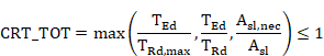
This value is stored in the CivilFEM results file for each end.
A value 2100 for this criterion indicates that any one of the torsion reinforcement groups are undefined.
For checking sections subjected to shear force and concomitant torsional moment, we follow the steps below:
1) Torsion checking considering a null shear force. This check follows the same procedure as for the check of elements subjected to pure torsion according to Eurocode 2 (EN 1992-1-1:2004/AC:2008) and ITER Design Code.
2) Shear checking assuming a null torsional moment. . This check follows the same steps as for the check of elements subjected to pure shear according to Eurocode 2 (EN 1992-1-1:2004/AC:2008) and ITER Design Code.
3)
Checking the concrete ultimate strength
condition. The design torsional moment (![]() ) and the design
shear force (
) and the design
shear force (![]() ) must satisfy the
following condition:
) must satisfy the
following condition:
![]()
4) Obtaining the combined shear and torsion criterion. This criterion comprehends pure shear, pure torsion and ultimate strength condition criteria of concrete. The criterion determines whether the section is valid and is defined as follows:

A value 2100 for this criterion indicates that ![]() or
or ![]() are equal to zero or
that one of the torsion reinforcement groups has not been defined.
are equal to zero or
that one of the torsion reinforcement groups has not been defined.
Shear reinforcement design according to Eurocode 2 (EN 1992-1-1:2004/AC:2008) and ITER Design Code follows the steps below:
1) Obtaining strength properties of the materials. The required material properties associated with each transverse cross section at the active time are:
![]() characteristic
strength of concrete.
characteristic
strength of concrete.
![]() characteristic design strength of concrete.
characteristic design strength of concrete.
![]() characteristic yield strength of reinforcement.
characteristic yield strength of reinforcement.
![]() design
strength of shear reinforcement.
design
strength of shear reinforcement.
2) Obtaining geometrical data of the section. Required data for shear design are the following:
![]() total
cross-sectional area of the concrete section.
total
cross-sectional area of the concrete section.
3) Obtaining geometrical parameters depending on specified code. Required data are as follows:
![]() minimum width of the section over the effective depth.
minimum width of the section over the effective depth.
d effective depth of the section.
![]() ratio of
the longitudinal tensile :
ratio of
the longitudinal tensile :
![]()
where:
![]() the area of
the tensile reinforcement extending not less than
the area of
the tensile reinforcement extending not less than ![]() beyond the section
considered.
beyond the section
considered.
q angle of the compressive struts of concrete with the member’s longitudinal axis:
1.0 £ cotan q£ 2.5 Eurocode 2 (EN 1992-1-1:2004/AC:2008)
1.0 £ cotan q £ cotan q0 ITER Design Code
Compressive mean stress ![]()
Tensile
mean stress ![]()
Section 6.6.1. provides detailed information on how to calculate the required data for each code and valid section.
4) Obtaining reinforcement data of the section. For shear reinforcement design, it is possible to define the angle between the reinforcement and the longitudinal axis of member can be indicated. This angle should be included in the reinforcement definition of each element. If this angle is null or is not defined, =90° is used. Other reinforcement data will be ignored.
5) Obtaining forces and moments acting on the section. The shear force that acts on the section as well as the concomitant axial force and bending moment, are obtained from the CivilFEM results file (.RCF).
Force Description
![]() Design shear force
Design shear force
![]() Design
axial force (positive for compression)
Design
axial force (positive for compression)
![]() Design
bending moment (³ 0)
Design
bending moment (³ 0)
6)
Checking whether the section requires
shear reinforcement. First,
the design shear (![]() ) is compared to the design shear resistance (
) is compared to the design shear resistance (![]() ):
):
![]()
![]()
with the constraints:

where:
|
|
= |
|
|
|
|
in MPa |
|
k |
= |
|
|
|
= |
|
|
|
= |
0.15 |
|
|
= |
|
|
|
|
in mm2 |
|
|
|
|
|
|
||
|
|
= |
|
|
|
|
in N |
Results are written for each element end in the CivilFEM results file as the parameters:
|
|
|
|
|
|
|
|
7) Calculating the maximum shear force that can be resisted by the concrete compressive struts.
A check is made
to ensure that ![]() is less than
is less than![]() :
:
Eurocode 2 (EN 1992-1-1:2004/AC:2008):
![]()
ITER Design Code:
![]()
where:

a = 90º if shear reinforcement was determined as not necessary in the previous step. If reinforcement is necessary, the angle a will be read from in the reinforcement definition data.
Results are written for each element end in the CivilFEM results file as the parameters:
|
|
|
|
|
|
|
|
If design shear force is greater than the force required to crush the concrete compressive struts, the reinforcement design will not be feasible, so the parameter containing this datum will be marked with 2100.
If the struts are not crushed by oblique compression, the calculating process continues.
8) Calculating required amount of transverse reinforcement. The section validity condition pertaining to shear force is:
![]()
Therefore, the reinforcement amount per length unit should be:

While also satisfying the following condition (Eurocode 2 only):

If the design is not possible, the reinforcement will be defined as 2100 and labeled as not designed.
The design criterion will be 1 (Ok) if the element was designed or 0 (Not Ok) if not.
For each element end, the results are included in the CivilFEM results file as the following parameters:
|
|
|
|
|
|
|
|
|
DSG_CRT |
= |
Design criterion |
Torsion reinforcement design according to Eurocode 2 (EN 1992-1-1:2004/AC:2008) and ITER Design Code follows the steps below:
1) Obtaining strength properties of the materials. These properties are obtained from the material properties associated to each transverse cross section and for the active time. Those material properties should be previously defined. The Required data are as follows:
![]() characteristic
strength of concrete.
characteristic
strength of concrete.
![]() characteristic design strength of concrete.
characteristic design strength of concrete.
![]() characteristic yield strength of reinforcement.
characteristic yield strength of reinforcement.
![]() design
strength of shear reinforcement. The same material will be considered for
transverse and longitudinal reinforcement.
design
strength of shear reinforcement. The same material will be considered for
transverse and longitudinal reinforcement.
2) Obtaining geometrical parameters depending on specified code. The required data are as follows:
t equivalent thickness of wall.
![]() area enclosed within the centre-line of the thin-walled
cross-section.
area enclosed within the centre-line of the thin-walled
cross-section.
![]() circumference of area
circumference of area ![]() .
.
q angle between the concrete compressive struts and the longitudinal axis of the member:
1.0 £ cotan q £ 2.5 Eurocode 2 (EN 1992-1-1:2004/AC:2008)
1.0 £ cotan q £ cotan q0 ITER Design Code
Compressive mean stress ![]()
Tensile
mean stress ![]()
Section 6.6.1. provides detailed information on how to calculate the required data for each code and valid section.
3) Obtaining forces and moments acting on the section. The torsional moment that acts on the section is obtained from the CivilFEM results file.
Moment Description
![]() Design torsional moment in I-section.
Design torsional moment in I-section.
4) Checking crushing of concrete compressive struts. First, it is necessary to check that the design torsional moment (![]() ) is less than or
equal to the maximum torsional moment that can be resisted by the concrete
compressive struts (
) is less than or
equal to the maximum torsional moment that can be resisted by the concrete
compressive struts (![]() ):
):
![]()
![]()
Where the values ![]() and
and ![]() are the same as the used previously.
are the same as the used previously.
Calculation results are written in the CivilFEM results file for both element ends as the parameters:
|
|
|
|
|
|
|
|
If the design torsional moment is greater than the moment required to crush the concrete compressive struts, the reinforcement design will not be feasible. As a result, the parameter for the reinforcement will contain a value of 2100.
![]() for transverse reinforcement
for transverse reinforcement
![]() for
longitudinal reinforcement
for
longitudinal reinforcement
In this case, the element will be labeled as not designed.
If there is no crushing due to compression, the calculation process continues.
5) Determining the required transverse reinforcement ratio. The required transverse reinforcement is defined by this expression:
![]()
The area of the designed transverse reinforcement per unit length is stored in the CivilFEM results file as the parameter:
![]()
6) Determining the required longitudinal reinforcement ratio. The longitudinal reinforcement is calculated as:
![]()
The area of the designed longitudinal reinforcement is stored in the CivilFEM results file as the parameter:
![]()
If both transverse and longitudinal reinforcements are designed for both element sections, this element will be labeled as designed.
Design criterion (DSG_CRT) is 1 (Ok) if the element was designed, 0 (Not OK) if not.
The design of sections subjected to shear force and concomitant torsional moment, follows the steps below:
1) Torsion design considering a null shear force. This design follows the same steps as for the design of elements subjected to pure torsion according to Eurocode 2 (EN 1992-1-1:2004/AC:2008) and ITER Design Code.
2) Shear design considering a null torsion force. This design is accomplished with the same steps as for the design of elements subjected to pure shear according to Eurocode 2 (EN 1992-1-1:2004/AC:2008) and ITER Design Code.
3)
Checking concrete ultimate strength
condition. The design
torsional moment (![]() ) and the design shear force (
) and the design shear force (![]() ) must satisfy the following condition:
) must satisfy the following condition:
![]()
4) Obtaining required shear and torsion reinforcement ratios. If the concrete ultimate strength condition is fulfilled (i.e. the concrete can resist the combined shear and torsion action) the reinforcements calculated in steps 1 and 2 are taken as the designed reinforcements. The element is then labeled as designed.
If the concrete ultimate strength condition is not fulfilled, the parameters corresponding to each type of reinforcement will take the value of 2100.
The design criterion is 1 (Ok) if the element has been designed, and 0 if not.
Checking elements for shear according to Structuaral Code (Annex 19) follows the steps below:
1) Obtaining strength properties of the materials. The required material properties associated with each transverse cross section at the active time are:
![]() characteristic compressive strength of
concrete.
characteristic compressive strength of
concrete.
![]() design strength of concrete.
design strength of concrete.
![]() characteristic yield strength of
reinforcement.
characteristic yield strength of
reinforcement.
![]() design strength of shear reinforcement.
design strength of shear reinforcement.
2) Obtaining geometrical data of the section. Required data for shear checking are the following ones:
![]() total
cross-sectional area of the concrete section.
total
cross-sectional area of the concrete section.
3) Obtaining geometrical parameters depending on code. Required data are as follows:
![]() minimum width of the section over the effective depth.
minimum width of the section over the effective depth.
d effective depth of the section.
![]() ratio of
the tension longitudinal reinforcement
ratio of
the tension longitudinal reinforcement
![]()
where:
![]() the area of
the tension reinforcement extending not less than
the area of
the tension reinforcement extending not less than ![]() beyond the section
considered.
beyond the section
considered.
q angle of the compressive struts of concrete with the member’s longitudinal axis, (parameter THETA):
![]()
Section 6.6.1. provides detailed information on how to calculate the required data for each code and valid section.
4) Obtaining reinforcement data of the section. Required data are as follows:
a angle between shear reinforcement and the longitudinal axis of the member section, (parameter ALPHA).
![]() area of
reinforcement per unit length, (parameters ASSY or ASSZ).
area of
reinforcement per unit length, (parameters ASSY or ASSZ).
The reinforcement ratio may also be obtained with the following data:
![]() total area
of the reinforcement legs, (parameters ASY or ASZ, both
Y and Z directions are available).
total area
of the reinforcement legs, (parameters ASY or ASZ, both
Y and Z directions are available).
s spacing of the stirrups.
or with the following ones:
s spacing of the stirrups.
φ diameter of bars, (parameter PHI).
N number of reinforcement legs, (parameters NY or NZ for Y and Z directions).
5) Obtaining the section’s internal forces and moments. The shear force that acts on the section, as well as the concomitant axial force and bending moment, are obtained from the CivilFEM results file (.RCF).
Force Description
![]() Design shear force (³ 0)
Design shear force (³ 0)
![]() Design axial force (positive for compression)
Design axial force (positive for compression)
![]() Design bending moment (³ 0)
Design bending moment (³ 0)
6) Checking whether the section requires shear reinforcement. First, the design shear (![]() ) is compared to the design shear resistance (
) is compared to the design shear resistance (![]() ):
):
![]()
![]()
with the constraints:
![]()
![]()
where:
|
|
= |
|
|
|
= |
in MPa |
|
k |
= |
|
|
k1 |
= |
0.15 |
|
|
= |
|
|
|
|
in mm2 |
|
|
= |
|
|
|
||
|
|
= |
|
|
|
|
in N |
If shear reinforcement has not been defined
for the section, a check is made to ensure ![]() is less than the lowest value between the shear reinforcement resistance,
is less than the lowest value between the shear reinforcement resistance,
![]()
and the maximum design shear reinforcement resistance:
![]()
Where :
The shear reinforcement must be equal to or less than
![]()
Results are written for each end in the CivilFEM results file as the following parameters:
|
VRDC |
= |
|
||||||
|
VRDS |
= |
|
||||||
|
VRDMAX |
= |
|
||||||
|
TENS |
= |
|
||||||
|
|
|
Tension resistance of the longitudinal reinforcement |
||||||
|
CRT_1 |
= |
|
||||||
|
CRT_2 |
= |
|
||||||
|
CRT_3 |
= |
|
8) Obtaining shear criterion. The shear criterion indicates whether the section is valid for the design forces (if it is less than 1, the section satisfies the code provisions; whereas if it exceeds 1, the section will not be valid). Furthermore, it includes information pertaining to how close the design force is to the ultimate section strength. The shear criterion is defined as follows:
|
CRT_TOT |
= |
|
A value of 2100
for this criterion indicates that ![]() or
or ![]() are equal to zero.
are equal to zero.
The torsion checking according to Structuaral Code (Annex 19) follows the steps below:
1) Obtaining strength properties of the materials. These properties are obtained from the material properties associated to the transverse cross section and for the active time.
The Required data are as follows:
![]() characteristic
strength of concrete.
characteristic
strength of concrete.
![]() calculation strength of concrete.
calculation strength of concrete.
![]() characteristic yield strength of reinforcement.
characteristic yield strength of reinforcement.
![]() calculation
torsion resistance of reinforcement. The same material
is considered for transverse and longitudinal reinforcement
calculation
torsion resistance of reinforcement. The same material
is considered for transverse and longitudinal reinforcement
2) Obtaining geometrical parameters depending on specified code. The required data are as follows:
t equivalent thickness of wall.
![]() area
enclosed within the centre-line of the thin-walled cross-section.
area
enclosed within the centre-line of the thin-walled cross-section.
![]() circumference
of area Ak.
circumference
of area Ak.
q Angle of the compressive struts of concrete with the member’s longitudinal axis:
0.5 £ cotan q £ 2
Section 6.6.1. provides detailed information on how to calculate the required data for each code and valid section.
3) Obtaining reinforcement data of the section. Required data are as follows:
Transverse reinforcement
![]() area of
transverse reinforcement per unit length.
area of
transverse reinforcement per unit length.
The reinforcement ratio can alternatively be defined using the following data:
![]() closed
stirrups area for torsion.
closed
stirrups area for torsion.
s spacing of closed stirrups.
Or with the following data:
s spacing of closed stirrups.
![]() diameter
of the closed stirrups.
diameter
of the closed stirrups.
Longitudinal Reinforcement
![]() total
area of the longitudinal reinforcement.
total
area of the longitudinal reinforcement.
The reinforcement ratio can alternatively be defined using the following data:
![]() diameter
of longitudinal bars.
diameter
of longitudinal bars.
N number of longitudinal bars.
4) Obtaining section internal forces and moments. The torsional moment that acts on the section is obtained from the CivilFEM results file (.RCF).
Moment Description
![]() Design
torsional moment
Design
torsional moment
5) Calculating the maximum torsional moment that can be resisted by the
concrete compressive struts. The design torsional
moment (![]() ) must be less than
or equal to the maximum torsional moment that can be resisted by the concrete
compressive struts (
) must be less than
or equal to the maximum torsional moment that can be resisted by the concrete
compressive struts (![]() ); therefore, the following condition must be fulfilled:
); therefore, the following condition must be fulfilled:
![]()
![]()
Where the values de of ![]() and
and ![]() are the same as those used in shear checking,
are the same as those used in shear checking,
Results are written in the CivilFEM results file for both element ends as the parameters:
|
TRDMAX |
= |
|
|
CRT_1 |
= |
|
6) Calculating the maximum torsional moment that can be resisted by the
reinforcement. The design
torsional moment (![]() ) must be less than or equal to the maximum design torsional moment
that can be resisted by the reinforcement (
) must be less than or equal to the maximum design torsional moment
that can be resisted by the reinforcement (![]() ); consequently, the following condition must be fulfilled:
); consequently, the following condition must be fulfilled:
![]()
![]()
Calculation results are written in the CivilFEM results file for both element ends as the parameters:
|
TRD |
= |
|
|
CRT_2 |
= |
|
If transverse reinforcement is not defined, ![]() and the criterion
will take the value of 2100.
and the criterion
will take the value of 2100.
7) Calculating the required longitudinal reinforcement. The required longitudinal reinforcement is calculated from ![]() as follows:
as follows:
If longitudinal reinforcement is not defined, ![]() and the criterion
will be 2100.
and the criterion
will be 2100.
|
ALT |
= |
|
|
CRTALT |
= |
|
8) Obtaining torsion criterion. The torsion criterion is defined as the ratio of the design moment to the section ultimate resistance: if it is less than 1, the section is valid; whereas if it exceeds 1, the section is not valid. The criterion pertaining to the validity for torsion is defined as follows:
This value is stored in the CivilFEM results file for each end.
A value 2100 for this criterion indicates that any one of the torsion reinforcement groups are undefined.
For checking sections subjected to shear force and concomitant torsional moment, we follow the steps below:
5) Torsion checking considering a null shear force. This check follows the same procedure as for the check of elements subjected to pure torsion according to Structuaral Code (Annex 19).
6) Shear checking assuming a null torsional moment. . This check follows the same steps as for the check of elements subjected to pure shear according to Structuaral Code (Annex 19).
7)
Checking the concrete ultimate strength
condition. The design torsional moment (![]() ) and the design
shear force (
) and the design
shear force (![]() ) must satisfy the
following condition:
) must satisfy the
following condition:
![]()
8) Obtaining the combined shear and torsion criterion. This criterion comprehends pure shear, pure torsion and ultimate strength condition criteria of concrete. The criterion determines whether the section is valid and is defined as follows:
A value 2100
for this criterion indicates that ![]() or
or ![]() are equal to zero or
that one of the torsion reinforcement groups has not been defined.
are equal to zero or
that one of the torsion reinforcement groups has not been defined.
Shear reinforcement design according to Structuaral Code (Annex 19) follows the steps below:
1) Obtaining strength properties of the materials. The required material properties associated with each transverse cross section at the active time are:
![]() characteristic
strength of concrete.
characteristic
strength of concrete.
![]() characteristic design strength of concrete.
characteristic design strength of concrete.
![]() characteristic yield strength of reinforcement.
characteristic yield strength of reinforcement.
![]() design
strength of shear reinforcement.
design
strength of shear reinforcement.
2) Obtaining geometrical data of the section. Required data for shear design are the following:
![]() total
cross-sectional area of the concrete section.
total
cross-sectional area of the concrete section.
3) Obtaining geometrical parameters depending on specified code. Required data are as follows:
![]() minimum width of the section over the effective depth.
minimum width of the section over the effective depth.
d effective depth of the section.
![]() ratio of
the longitudinal tensile :
ratio of
the longitudinal tensile :
![]()
where:
![]() the area of
the tensile reinforcement extending not less than
the area of
the tensile reinforcement extending not less than ![]() beyond the section
considered.
beyond the section
considered.
q angle of the compressive struts of concrete with the member’s longitudinal axis:
0.5 £ cotan q£ 2
Section 6.6.1. provides detailed information on how to calculate the required data for each code and valid section.
4) Obtaining reinforcement data of the section. For shear reinforcement design, it is possible to define the angle between the reinforcement and the longitudinal axis of member can be indicated. This angle should be included in the reinforcement definition of each element. If this angle is null or is not defined, =90° is used. Other reinforcement data will be ignored.
5) Obtaining forces and moments acting on the section. The shear force that acts on the section as well as the concomitant axial force and bending moment, are obtained from the CivilFEM results file (.RCF).
Force Description
![]() Design shear force
Design shear force
![]() Design
axial force (positive for compression)
Design
axial force (positive for compression)
![]() Design
bending moment (³ 0)
Design
bending moment (³ 0)
6)
Checking whether the section requires
shear reinforcement. First,
the design shear (![]() ) is compared to the design shear resistance (
) is compared to the design shear resistance (![]() ):
):
![]()
![]()
with the constraints:
where:
|
|
= |
|
|
|
|
in MPa |
|
k |
= |
|
|
|
= |
|
|
|
= |
0.15 |
|
|
= |
|
|
|
|
in mm2 |
|
|
|
|
|
|
||
|
|
= |
|
|
|
|
in N |
Results are written for each element end in the CivilFEM results file as the parameters:
|
|
|
|
|
|
|
|
7) Calculating the maximum shear force that can be resisted by the concrete compressive struts.
A check is made
to ensure that ![]() is less than
is less than![]() :
:
![]()
where:
a = 90º if shear reinforcement was determined as not necessary in the previous step. If reinforcement is necessary, the angle a will be read from in the reinforcement definition data.
Results are written for each element end in the CivilFEM results file as the parameters:
|
|
|
|
|
|
|
|
If design shear force is greater than the force required to crush the concrete compressive struts, the reinforcement design will not be feasible, so the parameter containing this datum will be marked with 2100.
If the struts are not crushed by oblique compression, the calculating process continues.
8) Calculating required amount of transverse reinforcement. The section validity condition pertaining to shear force is:
![]()
Therefore, the reinforcement amount per length unit should be:
While also satisfying the following condition (Eurocode 2 only):
If the design is not possible, the reinforcement will be defined as 2100 and labeled as not designed.
The design criterion will be 1 (Ok) if the element was designed or 0 (Not Ok) if not.
For each element end, the results are included in the CivilFEM results file as the following parameters:
|
|
|
|
|
|
|
|
|
DSG_CRT |
= |
Design criterion |
Torsion reinforcement design according to Structuaral Code (Annex 19) follows the steps below:
1) Obtaining strength properties of the materials. These properties are obtained from the material properties associated to each transverse cross section and for the active time. Those material properties should be previously defined. The Required data are as follows:
![]() characteristic
strength of concrete.
characteristic
strength of concrete.
![]() characteristic design strength of concrete.
characteristic design strength of concrete.
![]() characteristic yield strength of reinforcement.
characteristic yield strength of reinforcement.
![]() design
strength of shear reinforcement. The same material will be considered for
transverse and longitudinal reinforcement.
design
strength of shear reinforcement. The same material will be considered for
transverse and longitudinal reinforcement.
2) Obtaining geometrical parameters depending on specified code. The required data are as follows:
t equivalent thickness of wall.
![]() area enclosed within the centre-line of the thin-walled cross-section.
area enclosed within the centre-line of the thin-walled cross-section.
![]() circumference of area
circumference of area ![]() .
.
q angle between the concrete compressive struts and the longitudinal axis of the member:
0.5 £ cotan q £ 2.0
Section 6.6.1. provides detailed information on how to calculate the required data for each code and valid section.
3) Obtaining forces and moments acting on the section. The torsional moment that acts on the section is obtained from the CivilFEM results file.
Moment Description
![]() Design torsional moment in I-section.
Design torsional moment in I-section.
4) Checking crushing of concrete compressive struts. First, it is necessary to check that the design torsional moment (![]() ) is less than or
equal to the maximum torsional moment that can be resisted by the concrete
compressive struts (
) is less than or
equal to the maximum torsional moment that can be resisted by the concrete
compressive struts (![]() ):
):
![]()
![]()
Where the values ![]() and
and ![]() are the same as the used previously.
are the same as the used previously.
Calculation results are written in the CivilFEM results file for both element ends as the parameters:
|
|
|
|
|
|
|
|
If the design torsional moment is greater than the moment required to crush the concrete compressive struts, the reinforcement design will not be feasible. As a result, the parameter for the reinforcement will contain a value of 2100.
![]() for transverse reinforcement
for transverse reinforcement
![]() for
longitudinal reinforcement
for
longitudinal reinforcement
In this case, the element will be labeled as not designed.
If there is no crushing due to compression, the calculation process continues.
5) Determining the required transverse reinforcement ratio. The required transverse reinforcement is defined by this expression:
![]()
The area of the designed transverse reinforcement per unit length is stored in the CivilFEM results file as the parameter:
![]()
6) Determining the required longitudinal reinforcement ratio. The longitudinal reinforcement is calculated as:
![]()
The area of the designed longitudinal reinforcement is stored in the CivilFEM results file as the parameter:
![]()
If both transverse and longitudinal reinforcements are designed for both element sections, this element will be labeled as designed.
Design criterion (DSG_CRT) is 1 (Ok) if the element was designed, 0 (Not OK) if not.
The design of sections subjected to shear force and concomitant torsional moment, follows the steps below:
1) Torsion design considering a null shear force. This design follows the same steps as for the design of elements subjected to pure torsion according to Structuaral Code (Annex 19).
2) Shear design considering a null torsion force. This design is accomplished with the same steps as for the design of elements subjected to pure shear according to Structuaral Code (Annex 19).
3)
Checking concrete ultimate strength condition. The design torsional moment (![]() ) and the design shear force (
) and the design shear force (![]() ) must satisfy the following condition:
) must satisfy the following condition:
![]()
4) Obtaining required shear and torsion reinforcement ratios. If the concrete ultimate strength condition is fulfilled (i.e. the concrete can resist the combined shear and torsion action) the reinforcements calculated in steps 1 and 2 are taken as the designed reinforcements. The element is then labeled as designed.
If the concrete ultimate strength condition is not fulfilled, the parameters corresponding to each type of reinforcement will take the value of 2100.
The design criterion is 1 (Ok) if the element has been designed, and 0 if not.
Strength reduction factor φ is taken as φ = 0.75 for shear and torsion according to Chapter 9.3.2 of Building Code Requirements for Structural Concrete Structures (ACI 318-05) document.
Shear checking according to ACI 318-05 is described in this section. These equations refer to US (British) units which include force, length, and time units of lb, in, and sec.
1) Obtaining strength properties of the materials. The required material properties associated with each transverse cross section at the active time are:
![]() specified
compressive strength of concrete.
specified
compressive strength of concrete.
![]() specified
yield strength of reinforcement.
specified
yield strength of reinforcement.
2) Obtaining geometrical data of the section. Required data for shear checking:
![]() area of
concrete section.
area of
concrete section.
3) Obtaining geometrical parameters depending on specified code. Required data:
![]() web width or diameter of circular section.
web width or diameter of circular section.
d distance from the extreme compressed fiber to the centroid of the longitudinal tensile reinforcement in the Y direction, (for circular sections this should not be less than the distance from the extreme compressed fiber to the centroid of the tensile reinforcement in the opposite half of the member).
Section 6.6.1. provides detailed information on how to calculate the required data for each code and valid section.
4) Obtaining reinforcement data of the section. Required data are as follows:
a angle between shear reinforcement and the longitudinal axis of the member section.
![]() area of the
reinforcement per unit length (reinforcement ratio) in both the Y and Z
directions.
area of the
reinforcement per unit length (reinforcement ratio) in both the Y and Z
directions.
The reinforcement ratio may also be obtained with the following data:
![]() total
area of the reinforcement legs.
total
area of the reinforcement legs.
s spacing of the stirrups.
or with the following input:
s spacing of the stirrups.
φ diameter of bars.
N number of reinforcement legs.
5) Obtaining forces and moments acting on the section. The forces that act on the section are obtained from the CivilFEM results file (.RCF).
Force Description
![]() Factored design shear force
Factored design shear force
![]() Factored axial force occurring simultaneously to the shear force
(positive for compression).
Factored axial force occurring simultaneously to the shear force
(positive for compression).
6) Calculating the shear strength provided by concrete for nonprestressed members. First, the shear strength provided by concrete (Vc) is calculated with the following expression:
![]()
where:
![]() square root
of specified compressive strength of concrete, in psi (always taken as less
than 100 psi).
square root
of specified compressive strength of concrete, in psi (always taken as less
than 100 psi).
For sections subject to a compressive axial force,

If section is subjected to a tensile force so that the tensile stress is less than 500 psi,
If the section
is subjected to a tensile force so that the tensile stress exceeds 500 psi, it
is assumed ![]() .
.
The calculation result for both element ends is stored in the CivilFEM results file as the parameter VC:
VC Shear strength provided by concrete.
![]()
7) Calculating the shear strength provided by shear reinforcement. The strength provided by shear reinforcement (![]() ) is calculated with
the following expression:
) is calculated with
the following expression:
![]()
where:
![]() yield
strength of the shear reinforcement (not greater than 60000 psi).
yield
strength of the shear reinforcement (not greater than 60000 psi).
The calculation result for both element ends is stored in the CivilFEM results file as the parameter VS:
VS Shear strength provided by transverse reinforcement.
8) Calculating the nominal shear strength of section. The nominal shear strength (![]() ) is the summation of
the provided by concrete and by the shear reinforcement:
) is the summation of
the provided by concrete and by the shear reinforcement:
![]()
This nominal strength as well as its ratio to the design shear are stored in the CivilFEM results file as the parameters:
VN Nominal shear strength.
![]()
CRTVN Ratio
of the design shear force (Vu) to the resistance ![]() .
.
![]()
If the strength provided by concrete is null,
and the shear reinforcement is not defined in the section, then ![]() , and the criterion
is equal to –1.
, and the criterion
is equal to –1.
9) Obtaining shear criterion. The section will be valid for shear if the following condition is fulfilled:
![]()
φ strength reduction factor of the section. φ = 0.75 for shear and torsion according to Chapter 9.3 of Building Code Requirements for Structural Concrete Structures (ACI 318-05) document.
Therefore, the validity shear criterion is defined as follows:
![]()
For each element, this value is stored in the CivilFEM results file as the parameter CRT_TOT.
If the strength provided by concrete is null
and the shear reinforcement is not defined in the section, then ![]() , and the criterion
is equal to 2100.
, and the criterion
is equal to 2100.
The ![]() value is stored in
CivilFEM results file as the parameter VFI.
value is stored in
CivilFEM results file as the parameter VFI.
The torsion checking according to ACI 318-05 is described in this section. These equations refer to US (British) units which include force, length, and time units of lb, in, and sec.
1) Obtaining strength properties of the materials. These properties are obtained from the material properties associated with each transverse cross section at the active time:
![]() specified
compressive strength of concrete.
specified
compressive strength of concrete.
![]() specified
yield strength of reinforcement.
specified
yield strength of reinforcement.
2) Obtaining geometrical parameters depending on specified code. The required data are as follows:
![]() web width or diameter of circular section.
web width or diameter of circular section.
d distance from the extreme compression fiber to the centroid of the longitudinal tensile reinforcement in Y, (for circular sections this should not be less than the distance from the extreme compression fiber to the centroid of the tensile reinforcement in the opposite half of the member).
![]() area
enclosed by outside perimeter of concrete cross section.
area
enclosed by outside perimeter of concrete cross section.
![]() outside
perimeter of the concrete cross section.
outside
perimeter of the concrete cross section.
![]() area
enclosed by centerline of the outermost closed transverse torsional
reinforcement.
area
enclosed by centerline of the outermost closed transverse torsional
reinforcement.
![]() perimeter
of centerline of outermost closed transverse torsional reinforcement.
perimeter
of centerline of outermost closed transverse torsional reinforcement.
![]() gross
area enclosed by shear flow path.
gross
area enclosed by shear flow path.
Section 6.6.1. provides detailed information on how to calculate the required data for each code and valid section.
3) Obtaining reinforcement data of the section. Required data are as follows:
Transverse Reinforcement
![]() area of
transverse reinforcement per unit of length.
area of
transverse reinforcement per unit of length.
The reinforcement ratio can alternatively be defined using the following data:
![]() closed
stirrups area for torsion.
closed
stirrups area for torsion.
s spacing of closed stirrups.
Or with the following data:
s spacing of closed stirrups.
![]() diameter
of the closed stirrups.
diameter
of the closed stirrups.
Longitudinal Reinforcement
![]() total
area of the longitudinal reinforcement.
total
area of the longitudinal reinforcement.
The reinforcement ratio can alternatively be defined using the following data:
![]() diameter
of longitudinal bars.
diameter
of longitudinal bars.
N number of longitudinal bars.
4) Obtaining section’s internal forces and moments. The torsional moment that acts on the section is obtained from the CivilFEM results file (.RCF).
Moment Description
![]() Factored
design torsional moment.
Factored
design torsional moment.
5) Checking if torsion effects will be considered. Torsion effects are only considered if the design torsional moment
(![]() ) satisfies the
condition below:
) satisfies the
condition below:

If the design
torsional moment is less than this value, its effects can be neglected and it
will be considered as null for checking.
Checking section dimensions. Section dimensions must satisfy the
following requirements:
![]()
In hollow
sections, if the section wall’s thickness is less than![]() , this value will be
replaced by the minimum thickness of the section in the previous formula.
, this value will be
replaced by the minimum thickness of the section in the previous formula.
The ratio of the two coefficients is stored in the CivilFEM results file for both element ends as the parameter:

6) Calculating the nominal torsional moment strength of the section. The nominal torsional moment strength (![]() ) is evaluated with
the following expression:
) is evaluated with
the following expression:
![]()
where:
![]() specified
yield strength of torsional reinforcement (not greater than 60,000 psi).
specified
yield strength of torsional reinforcement (not greater than 60,000 psi).
This nominal torsional moment strength and its ratio to the design shear force are stored in the CivilFEM results file for both element ends as the parameters:
TN Nominal torsional moment strength.
![]()
CRTTN Ratio
of the design torsional moment (![]() ) to the torsional
moment strength
) to the torsional
moment strength ![]() .
.
![]()
The required longitudinal reinforcement area is given by:
![]()
Calculation results are stored in the CivilFEM results file for both element ends as the parameters:
ALT Area of longitudinal torsion reinforcement required in accordance with the transverse torsion reinforcement defined.
![]()
CRTALT Ratio of the area of longitudinal torsion reinforcement required to the area of longitudinal torsion reinforcement defined.
![]()
If longitudinal reinforcement is not
defined, then ![]() and the criterion is
equal to 2100.
and the criterion is
equal to 2100.
7) Obtaining torsion criterion. The section will be valid for torsion if the following condition is fulfilled:
![]()
![]()
![]()
φ strength reduction factor of the section, (0.75 for shear and torsion).
Therefore, the validity torsion criterion is defined as follows:

For each element end, this value is stored in the CivilFEM results file as CRT_TOT.
If the strength provided by concrete is null and the torsion reinforcement is not defined in the section, the criterion will be 2100.
The ![]() value is stored in
the CivilFEM results file for both element ends as the parameter TFI.
value is stored in
the CivilFEM results file for both element ends as the parameter TFI.
For checking sections subjected to shear force and concomitant torsional moment, the following steps are taken:
1) Checking if torsion effects will be considered. Torsion effects are only considered if the design torsional moment
(![]() ) satisfies the
condition below:
) satisfies the
condition below:
If the design torsional moment is less than this value, its effects can be neglected and it is considered as null for checking.
2) Checking section dimensions. For shear force and the associated torsional moment, section dimensions must satisfy the following requirements:
a) Solid sections:

b) Hollow sections:
![]()
In hollow
sections, if the section wall’s thickness is less than ![]() , this value is replaced in the expression above by the section’s
minimum thickness.
, this value is replaced in the expression above by the section’s
minimum thickness.
The ratio between these two factors is stored in the CivilFEM results file for both element ends.
a) Solid sections:

b) Hollow sections:

3) Checking for shear force with concomitant torsional moment. This check is accomplished with the same steps as the check of elements subjected to pure shear force according to ACI 318-05. The same results as for shear checking will be calculated.
Except for this check, the CRT_TOT criterion is stored in the CivilFEM results file as CRTSHR for each element end.
4) Checking for torsion with shear force. This check follows the same steps considered for the check of elements subjected to pure torsion according to ACI 318-05. The same results as in torsion checking will be calculated.
Except for this check, the CRT_TOT criterion is stored in the CivilFEM results file as CRTTRS for each element end.
5) Obtaining the combined shear and torsion criterion. This criterion determines whether the section is valid or not. It is defined as follows:

For each end, this value is stored in the CivilFEM results file.
A value equal to 2100 for this criterion indicates:
h the shear strength provided by concrete is equal to zero and the shear reinforcement has not been defined.
h the shear strength provided by concrete is equal to zero and the transverse torsion reinforcement has not been defined.
h the longitudinal torsion reinforcement has not been defined.
The shear designing according to ACI 318-05 is described in this section. These equations refer to US (British) units which include force, length, and time units of lb, in, and sec.
1) Obtaining strength properties of the materials. The required material properties associated with each transverse cross section at the active time are:
![]() specified
compressive strength of concrete.
specified
compressive strength of concrete.
![]() specified
yield strength of reinforcement.
specified
yield strength of reinforcement.
2) Obtaining geometrical data of the section. Required data for shear designing are the following ones:
![]() area of
concrete section.
area of
concrete section.
3) Obtaining geometrical parameters depending on specified code. The Required data are as follows:
![]() web width or diameter of the circular section.
web width or diameter of the circular section.
d distance from the extreme compressed fiber to the centroid of the longitudinal tension reinforcement in Y, (for circular sections this should not be less than the distance from the extreme compressed fiber to the centroid of the tension reinforcement in the opposite half of the member).
Section 6.6.1. provides detailed information on how to calculate the required data for each code and valid section.
4) Obtaining reinforcement data of the section. For shear reinforcement design, it is possible to define the angle a between the reinforcement and the longitudinal axis of the member. This angle must be stored in the shear reinforcement data of each element. If this angle is equal to zero or it is not defined, = 90º. Other data pertaining to reinforcements will be ignored.
5) Obtaining forces and moments acting on the section. The shear force that acts on the section as well as the concomitant axial force are obtained from the CivilFEM results file (.RCF).
Force Description
![]() Design
shear force
Design
shear force
Nu Axial force (positive for compression)
6) Calculating the shear strength provided by concrete. The shear strength provided by concrete (![]() ) is calculated with
the following expression:
) is calculated with
the following expression:
![]()
where:
![]() square root
of specified compressive strength of concrete, in psi (always taken as less
than 100 psi).
square root
of specified compressive strength of concrete, in psi (always taken as less
than 100 psi).
For sections subject to a compressive axial force,
If the section is subjected to a tensile force so that the tensile stress is less than 500 psi,

If the section
is subjected to a tensile force so that the tensile stress exceeds 500 psi, it
is assumed![]() .
.
The calculation result is stored in the CivilFEM results file for both element ends as the parameter:
VC Shear
strength provided by concrete: ![]()
7) Calculating the required reinforcement contribution to the shear strength. The section must satisfy the following condition to resist the shear force:
![]() =
= ![]()
Therefore, the reinforcement shear resistance must satisfy:
![]()
If the shear resistance of the reinforcement does not satisfy the expression above, the section cannot be designed. As a result, the parameters for the reinforcement ratio will be equal to 2100.
![]()
For this case, the element will be labeled as not designed.
Calculation results are stored in the CivilFEM results file for both element ends as the parameter:
VS Shear resistance provided by the transverse reinforcement.
![]()
8) Calculating the required reinforcement ratio. Once the shear resistance of the reinforcement has been obtained, the reinforcement can be calculated with the following expression:

Where:
![]() area of the cross-section of the shear reinforcement.
area of the cross-section of the shear reinforcement.
s spacing of the stirrups measured along the longitudinal axis.
![]() yield
strength of the shear reinforcement (not greater than 60000 psi).
yield
strength of the shear reinforcement (not greater than 60000 psi).
The area of the designed reinforcement per unit length is stored in the CivilFEM results file for both element ends:
![]()
In this case, the element will be labeled as designed (providing the design process is correct for both element sections).
The torsion designing according to ACI 318-05 is described in this section. These equations refer to US (British) units which include force, length, and time units of lb, in, and sec.
1) Obtaining strength properties of the materials. These properties are obtained from the material properties associated with each transverse cross section at the active time.
![]() specified
compressive strength of concrete.
specified
compressive strength of concrete.
![]() specified
yield strength of reinforcement.
specified
yield strength of reinforcement.
2) Obtaining geometrical parameters depending on specified code. The required data are as follows:
![]() web width or diameter of the circular section.
web width or diameter of the circular section.
d distance from the extreme compressed fiber to the centroid of the longitudinal tensile reinforcement in Y, (for circular sections this should not be less than the distance from the extreme compressed fiber to the centroid of the tensile reinforcement in the opposite half of the member).
![]() Area
enclosed by outside perimeter of concrete cross section.
Area
enclosed by outside perimeter of concrete cross section.
![]() Outside
perimeter of the concrete cross section.
Outside
perimeter of the concrete cross section.
![]() Area
enclosed by centerline of the outermost closed transverse torsional
reinforcement.
Area
enclosed by centerline of the outermost closed transverse torsional
reinforcement.
![]() Perimeter
of centerline of outermost closed transverse torsional reinforcement.
Perimeter
of centerline of outermost closed transverse torsional reinforcement.
![]() Gross
area enclosed by shear flow path.
Gross
area enclosed by shear flow path.
Section 6.6.1. provides detailed information on how to calculate the required data for each code and valid section.
3) Obtaining forces and moments acting on the section. The torsional moment that acts on the section is obtained from the CivilFEM results file (.RCF).
Moment Description
![]() Design
torsional moment in l section.
Design
torsional moment in l section.
4) Checking if torsion effects will be considered. Torsion effects are only considered if the design torsional moment
(![]() ) satisfies the condition
below:
) satisfies the condition
below:

If the design torsional moment is less than this value, its effects can be neglected and it is consider as null for the design.
5) Checking section dimensions. Section dimensions must satisfy the following requirements:
![]()
![]()
![]() For
hollow sections, if the thickness of the section walls is less than
For
hollow sections, if the thickness of the section walls is less than ![]() , this value will be replaced by the minimum thickness
of the section in the equation above.
, this value will be replaced by the minimum thickness
of the section in the equation above.
The torsion reinforcement will not be designed if the previous expression is not fulfilled; consequently, the parameters for the reinforcement will be equal to 2100.
![]() for transverse reinforcement
for transverse reinforcement
![]() for longitudinal reinforcement
for longitudinal reinforcement
In this case the element will be marked as not designed and it will be stored in the TRS_NOT OK component.
The ratio of the two coefficients is stored in the CivilFEM results file for both element ends:

6) Calculating the required transverse reinforcement. In order to resist the torsional moment, the section must satisfy the condition below:
![]()
![]() cross-sectional
area of one leg of a closed stirrup resisting torsion.
cross-sectional
area of one leg of a closed stirrup resisting torsion.
s spacing of the stirrups.
Therefore, the required transverse torsion reinforcement is:

The area of designed transverse reinforcement per unit length is stored in the CivilFEM results file for both element ends:
![]()
7) Calculating the required longitudinal reinforcement. The longitudinal reinforcement area is given by the following expression:
![]()
The area of the designed longitudinal reinforcement is stored in the CivilFEM results file for both element ends:
![]()
If transverse and longitudinal reinforcements are designed for both element ends, this element will be labeled as designed.
The designing of sections subjected to shear force and concomitant torsional moment, follows the steps below:
1)
Checking if torsion effects will be
considered. Torsion effects are only considered if
the design torsional moment (![]() ) satisfies the
condition below:
) satisfies the
condition below:
If the design torsional moment is less than this value, its effects can be neglected and it is considered as null for the design.
2) Checking section dimensions. For shear force and concomitant torsional moment, section dimensions must satisfy the following requirements:
a) Solid sections:

b) Hollow sections:

![]()
![]() For hollow sections, if the section
wall’s thickness is less than
For hollow sections, if the section
wall’s thickness is less than ![]() , this value will be
, this value will be
replaced by the minimum thickness of the section in the expression above.
The torsion reinforcement will not be designed if the expression above is not fulfilled; consequently, the parameters for the reinforcement will be equal to 2100.
![]() for transverse reinforcement
for transverse reinforcement
![]() for longitudinal reinforcement
for longitudinal reinforcement
In this case, the element will be marked as not designed.
The ratio of the two coefficients is stored in the CivilFEM results file for both element ends.
a) Solid sections:

b) Hollow sections:

3) Shear design assuming a null torsional moment. This design follows the same procedure as for the design of elements subjected to pure shear force according to ACI 318-05.
4) Torsion design considering a null shear force. This design is accomplished with the same steps as for the design of elements subjected to pure torsion according to ACI 318-05.
Strength reduction factor φ is taken as φ = 0.75 for shear and torsion according to Chapter 21.2.1 of Building Code Requirements for Structural Concrete Structures (ACI 318-14) document.
Shear checking according to ACI 318-14 is described in this section. These equations refer to US (British) units which include force, length, and time units of lb, in, and sec.
1) Obtaining strength properties of the materials. The required material properties associated with each transverse cross section at the active time are:
![]() specified
compressive strength of concrete.
specified
compressive strength of concrete.
![]() specified
yield strength of reinforcement.
specified
yield strength of reinforcement.
![]() modification
factor for lightweight concrete (
modification
factor for lightweight concrete (![]() ).
).
2) Obtaining geometrical data of the section. Required data for shear checking:
![]() area of
concrete section.
area of
concrete section.
3) Obtaining geometrical parameters depending on specified code. Required data:
![]() web width or diameter of circular section.
web width or diameter of circular section.
d distance from the extreme compressed fiber to the centroid of the longitudinal tensile reinforcement in the Y direction, (for circular sections this should not be less than the distance from the extreme compressed fiber to the centroid of the tensile reinforcement in the opposite half of the member).
Section 6.6.1. provides detailed information on how to calculate the required data for each code and valid section.
4) Obtaining reinforcement data of the section. Required data are as follows:
a angle between shear reinforcement and the longitudinal axis of the member section.
![]() area of the
reinforcement per unit length (reinforcement ratio) in both the Y and Z
directions.
area of the
reinforcement per unit length (reinforcement ratio) in both the Y and Z
directions.
The reinforcement ratio may also be obtained with the following data:
![]() total
area of the reinforcement legs.
total
area of the reinforcement legs.
s spacing of the stirrups.
or with the following input:
s spacing of the stirrups.
φ diameter of bars.
N number of reinforcement legs.
5) Obtaining forces and moments acting on the section. The forces that act on the section are obtained from the CivilFEM results file (.RCF).
Force Description
![]() Factored design shear force
Factored design shear force
![]() Factored axial force occurring simultaneously to the shear force
(positive for compression).
Factored axial force occurring simultaneously to the shear force
(positive for compression).
6) Calculating the shear strength provided by concrete for nonprestressed members. First, the shear strength provided by concrete (Vc) is calculated with the following expression for sections without axial force:
![]()
where:
![]() square root
of specified compressive strength of concrete, in psi (always taken as less
than 100 psi).
square root
of specified compressive strength of concrete, in psi (always taken as less
than 100 psi).
For sections subject to a compressive axial force,

If section is subjected to significant tensile force,

The calculation result for both element ends is stored in the CivilFEM results file as the parameter VC:
VC Shear strength provided by concrete.
![]()
7) Calculating the shear strength provided by shear reinforcement. The strength provided by shear reinforcement (![]() ) is calculated with
the following expression:
) is calculated with
the following expression:
![]()
where:
![]() yield
strength of the shear reinforcement (not greater than 60000 psi).
yield
strength of the shear reinforcement (not greater than 60000 psi).
The calculation result for both element ends is stored in the CivilFEM results file as the parameter VS:
VS Shear strength provided by transverse reinforcement.
8) Calculating the nominal shear strength of section. The nominal shear strength (![]() ) is the summation of
the provided by concrete and by the shear reinforcement:
) is the summation of
the provided by concrete and by the shear reinforcement:
![]()
This nominal strength as well as its ratio to the design shear are stored in the CivilFEM results file as the parameters:
VN Nominal shear strength.
![]()
CRTVN Ratio
of the design shear force (Vu) to the resistance ![]() .
.
![]()
If the strength provided by concrete is null,
and the shear reinforcement is not defined in the section, then ![]() , and the criterion
is equal to –1.
, and the criterion
is equal to –1.
9) Obtaining shear criterion. The section will be valid for shear if the following condition is fulfilled:
![]()
φ strength reduction factor of the section (0.75 for shear and torsion).
Therefore, the validity shear criterion is defined as follows:
![]()
For each element, this value is stored in the CivilFEM results file as the parameter CRT_TOT.
If the strength provided by concrete is null
and the shear reinforcement is not defined in the section, then ![]() , and the criterion
is equal to 2100.
, and the criterion
is equal to 2100.
The ![]() value is stored in
CivilFEM results file as the parameter VFI.
value is stored in
CivilFEM results file as the parameter VFI.
The torsion checking according to ACI 318-14 is described in this section. These equations refer to US (British) units which include force, length, and time units of lb, in, and sec.
1) Obtaining strength properties of the materials. These properties are obtained from the material properties associated with each transverse cross section at the active time:
![]() specified
compressive strength of concrete.
specified
compressive strength of concrete.
![]() specified
yield strength of reinforcement.
specified
yield strength of reinforcement.
![]() modification
factor for lightweight concrete.
modification
factor for lightweight concrete.
2) Obtaining geometrical parameters depending on specified code. The required data are as follows:
![]() web width or diameter of circular section.
web width or diameter of circular section.
d distance from the extreme compression fiber to the centroid of the longitudinal tensile reinforcement in Y, (for circular sections this should not be less than the distance from the extreme compression fiber to the centroid of the tensile reinforcement in the opposite half of the member).
![]() area
enclosed by outside perimeter of concrete cross section.
area
enclosed by outside perimeter of concrete cross section.
![]() outside
perimeter of the concrete cross section.
outside
perimeter of the concrete cross section.
![]() area
enclosed by centerline of the outermost closed transverse torsional reinforcement.
area
enclosed by centerline of the outermost closed transverse torsional reinforcement.
![]() perimeter
of centerline of outermost closed transverse torsional reinforcement.
perimeter
of centerline of outermost closed transverse torsional reinforcement.
![]() gross
area enclosed by shear flow path.
gross
area enclosed by shear flow path.
Section 6.6.1.. provides detailed information on how to calculate the required data for each code and valid section.
3) Obtaining reinforcement data of the section. Required data are as follows:
Transverse Reinforcement
![]() area of
transverse reinforcement per unit of length.
area of
transverse reinforcement per unit of length.
The reinforcement ratio can alternatively be defined using the following data:
![]() closed
stirrups area for torsion.
closed
stirrups area for torsion.
s spacing of closed stirrups.
Or with the following data:
s spacing of closed stirrups.
![]() diameter
of the closed stirrups.
diameter
of the closed stirrups.
Longitudinal Reinforcement
![]() total
area of the longitudinal reinforcement.
total
area of the longitudinal reinforcement.
The reinforcement ratio can alternatively be defined using the following data:
![]() diameter
of longitudinal bars.
diameter
of longitudinal bars.
N number of longitudinal bars.
4) Obtaining section’s internal forces and moments. The torsional moment that acts on the section is obtained from the CivilFEM results file (.RCF).
Moment Description
![]() Factored
design torsional moment.
Factored
design torsional moment.
5) Checking if torsion effects will be considered. Torsion effects are only considered if the design torsional moment
(![]() ) satisfies the
condition below:
) satisfies the
condition below:

If the design
torsional moment is less than this value, its effects can be neglected and it
will be considered as null for checking.
Checking section dimensions. Section dimensions must satisfy the
following requirements for solid sections:

Hollow sections:
![]()
The ratio of the two coefficients is stored in the CivilFEM results file for both element ends as the parameter (solid sections):

Hollow sections:
6) Calculating the nominal torsional moment strength of the section. The nominal torsional moment strength (![]() ) is evaluated with
the following expression:
) is evaluated with
the following expression:
![]()
where:
![]() specified
yield strength of torsional reinforcement (not greater than 60,000 psi).
specified
yield strength of torsional reinforcement (not greater than 60,000 psi).
This nominal torsional moment strength and its ratio to the design shear force are stored in the CivilFEM results file for both element ends as the parameters:
TN Nominal torsional moment strength.
![]()
CRTTN Ratio
of the design torsional moment (![]() ) to the torsional
moment strength
) to the torsional
moment strength ![]() .
.
![]()
The required longitudinal reinforcement area is given by:
![]()
Calculation results are stored in the CivilFEM results file for both element ends as the parameters:
ALT Area of longitudinal torsion reinforcement required in accordance with the transverse torsion reinforcement defined.
![]()
CRTALT Ratio of the area of longitudinal torsion reinforcement required to the area of longitudinal torsion reinforcement defined.
![]()
If longitudinal reinforcement is not
defined, then ![]() and the criterion is
equal to 2100.
and the criterion is
equal to 2100.
7) Obtaining torsion criterion. The section will be valid for torsion if the following condition is fulfilled:
![]()
![]()
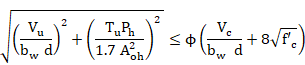
φ strength reduction factor of the section, (0.75 for shear and torsion).
Therefore, the validity torsion criterion is defined as follows:

For each element end, this value is stored in the CivilFEM results file as CRT_TOT.
If the strength provided by concrete is null and the torsion reinforcement is not defined in the section, the criterion will be 2100.
The ![]() value is stored in
the CivilFEM results file for both element ends as the parameter TFI.
value is stored in
the CivilFEM results file for both element ends as the parameter TFI.
For checking sections subjected to shear force and concomitant torsional moment, the following steps are taken:
6) Checking if torsion effects will be considered. Torsion effects are only considered if the design torsional moment
(![]() ) satisfies the
condition below:
) satisfies the
condition below:
If the design torsional moment is less than this value, its effects can be neglected and it is considered as null for checking.
7) Checking section dimensions. For shear force and the associated torsional moment, section dimensions must satisfy the following requirements:
a) Solid sections:
b) Hollow sections:
![]()
In hollow
sections, if the section wall’s thickness is less than ![]() , this value is replaced in the expression above by the section’s
minimum thickness.
, this value is replaced in the expression above by the section’s
minimum thickness.
The ratio between these two factors is stored in the CivilFEM results file for both element ends.
a) Solid sections:
b) Hollow sections:
8) Checking for shear force with concomitant torsional moment. This check is accomplished with the same steps as the check of elements subjected to pure shear force according to ACI 318-14. The same results as for shear checking will be calculated.
Except for this check, the CRT_TOT criterion is stored in the CivilFEM results file as CRTSHR for each element end.
9) Checking for torsion with shear force. This check follows the same steps considered for the check of elements subjected to pure torsion according to ACI 318-05. The same results as in torsion checking will be calculated.
Except for this check, the CRT_TOT criterion is stored in the CivilFEM results file as CRTTRS for each element end.
10) Obtaining the combined shear and torsion criterion. This criterion determines whether the section is valid or not. It is defined as follows:
For each end, this value is stored in the CivilFEM results file.
A value equal to 2100 for this criterion indicates:
h the shear strength provided by concrete is equal to zero and the shear reinforcement has not been defined.
h the shear strength provided by concrete is equal to zero and the transverse torsion reinforcement has not been defined.
h the longitudinal torsion reinforcement has not been defined.
The shear designing according to ACI 318-14 is described in this section. These equations refer to US (British) units which include force, length, and time units of lb, in, and sec.
1) Obtaining strength properties of the materials. The required material properties associated with each transverse cross section at the active time are:
![]() specified
compressive strength of concrete.
specified
compressive strength of concrete.
![]() specified
yield strength of reinforcement.
specified
yield strength of reinforcement.
![]() modification
factor for lightweight concrete.
modification
factor for lightweight concrete.
2) Obtaining geometrical data of the section. Required data for shear designing are the following ones:
![]() area of
concrete section.
area of
concrete section.
3) Obtaining geometrical parameters depending on specified code. The Required data are as follows:
![]() web width or diameter of the circular section.
web width or diameter of the circular section.
d distance from the extreme compressed fiber to the centroid of the longitudinal tension reinforcement in Y, (for circular sections this should not be less than the distance from the extreme compressed fiber to the centroid of the tension reinforcement in the opposite half of the member).
Section 6.6.1.. provides detailed information on how to calculate the required data for each code and valid section.
4) Obtaining reinforcement data of the section. For shear reinforcement design, it is possible to define the angle a between the reinforcement and the longitudinal axis of the member. This angle must be stored in the shear reinforcement data of each element. If this angle is equal to zero or it is not defined, alpha= 90º. Other data pertaining to reinforcements will be ignored.
5) Obtaining forces and moments acting on the section. The shear force that acts on the section as well as the concomitant axial force are obtained from the CivilFEM results file (.RCF).
Force Description
![]() Design
shear force
Design
shear force
Nu Axial force (positive for compression)
6) Calculating the shear strength provided by concrete. The shear strength provided by concrete (![]() ) is calculated with
the following expression:
) is calculated with
the following expression:
![]()
where:
![]() square root
of specified compressive strength of concrete, in psi (always taken as less
than 100 psi).
square root
of specified compressive strength of concrete, in psi (always taken as less
than 100 psi).
For sections subject to a compressive axial force,
If the section is subjected to a significant tensile force,
The calculation result is stored in the CivilFEM results file for both element ends as the parameter:
VC Shear
strength provided by concrete: ![]()
7) Calculating the required reinforcement contribution to the shear strength. The section must satisfy the following condition to resist the shear force:
![]() =
= ![]()
Therefore, the reinforcement shear resistance must satisfy:
![]()
If the shear resistance of the reinforcement does not satisfy the expression above, the section cannot be designed. As a result, the parameters for the reinforcement ratio will be equal to 2100.
![]()
For this case, the element will be labeled as not designed.
Calculation results are stored in the CivilFEM results file for both element ends as the parameter:
VS Shear resistance provided by the transverse reinforcement.
![]()
8) Calculating the required reinforcement ratio. Once the shear resistance of the reinforcement has been obtained, the reinforcement can be calculated with the following expression:
Where:
![]() area of the cross-section of the shear reinforcement.
area of the cross-section of the shear reinforcement.
s spacing of the stirrups measured along the longitudinal axis.
![]() yield
strength of the shear reinforcement (not greater than 60000 psi).
yield
strength of the shear reinforcement (not greater than 60000 psi).
The area of the designed reinforcement per unit length is stored in the CivilFEM results file for both element ends:
![]()
In this case, the element will be labeled as designed (providing the design process is correct for both element sections).
The torsion designing according to ACI 318-14 is described in this section. These equations refer to US (British) units which include force, length, and time units of lb, in, and sec.
1) Obtaining strength properties of the materials. These properties are obtained from the material properties associated with each transverse cross section at the active time.
![]() specified
compressive strength of concrete.
specified
compressive strength of concrete.
![]() specified
yield strength of reinforcement.
specified
yield strength of reinforcement.
![]() modification
factor for lightweight concrete.
modification
factor for lightweight concrete.
2) Obtaining geometrical parameters depending on specified code. The required data are as follows:
![]() web width or diameter of the circular section.
web width or diameter of the circular section.
d distance from the extreme compressed fiber to the centroid of the longitudinal tensile reinforcement in Y, (for circular sections this should not be less than the distance from the extreme compressed fiber to the centroid of the tensile reinforcement in the opposite half of the member).
![]() Area
enclosed by outside perimeter of concrete cross section.
Area
enclosed by outside perimeter of concrete cross section.
![]() Outside
perimeter of the concrete cross section.
Outside
perimeter of the concrete cross section.
![]() Area
enclosed by centerline of the outermost closed transverse torsional
reinforcement.
Area
enclosed by centerline of the outermost closed transverse torsional
reinforcement.
![]() Perimeter
of centerline of outermost closed transverse torsional reinforcement.
Perimeter
of centerline of outermost closed transverse torsional reinforcement.
![]() Gross
area enclosed by shear flow path.
Gross
area enclosed by shear flow path.
Section 6.6.1.. provides detailed information on how to calculate the required data for each code and valid section.
3) Obtaining forces and moments acting on the section. The torsional moment that acts on the section is obtained from the CivilFEM results file (.RCF).
Moment Description
![]() Design
torsional moment in l section.
Design
torsional moment in l section.
4) Checking if torsion effects will be considered. Torsion effects are only considered if the design torsional moment
(![]() ) satisfies the
condition below:
) satisfies the
condition below:

If the design torsional moment is less than this value, its effects can be neglected and it is consider as null for the design.
Checking section dimensions. Section dimensions must satisfy the following requirements for solid sections:
Hollow sections:
![]()
![]()
![]() For
hollow sections, if the thickness of the section walls is less than
For
hollow sections, if the thickness of the section walls is less than ![]() , this value will be replaced by the minimum thickness
of the section in the equation above.
, this value will be replaced by the minimum thickness
of the section in the equation above.
The torsion reinforcement will not be designed if the previous expression is not fulfilled; consequently, the parameters for the reinforcement will be equal to 2100.
![]() for transverse reinforcement
for transverse reinforcement
![]() for longitudinal reinforcement
for longitudinal reinforcement
In this case the element will be marked as not designed and it will be stored in the TRS_NOT OK component.
The ratio of the two coefficients is stored in the CivilFEM results file for both element ends:
a) Solid sections:

b) Hollow sections:

5) Calculating the required transverse reinforcement. In order to resist the torsional moment, the section must satisfy the condition below:
![]()
![]() cross-sectional
area of one leg of a closed stirrup resisting torsion.
cross-sectional
area of one leg of a closed stirrup resisting torsion.
s spacing of the stirrups.
Therefore, the required transverse torsion reinforcement is:
The area of designed transverse reinforcement per unit length is stored in the CivilFEM results file for both element ends:
![]()
6) Calculating the required longitudinal reinforcement. The longitudinal reinforcement area is given by the following expression:
![]()
The area of the designed longitudinal reinforcement is stored in the CivilFEM results file for both element ends:
![]()
If transverse and longitudinal reinforcements are designed for both element ends, this element will be labeled as designed.
The designing of sections subjected to shear force and concomitant torsional moment, follows the steps below:
5)
Checking if torsion effects will be
considered. Torsion effects are only considered if
the design torsional moment (![]() ) satisfies the
condition below:
) satisfies the
condition below:
If the design torsional moment is less than this value, its effects can be neglected and it is considered as null for the design.
6) Checking section dimensions. For shear force and concomitant torsional moment, section dimensions must satisfy the following requirements:
a) Solid sections:
b) Hollow sections:
![]()
![]() For hollow sections, if the section
wall’s thickness is less than
For hollow sections, if the section
wall’s thickness is less than ![]() , this value will be
, this value will be
replaced by the minimum thickness of the section in the expression above.
The torsion reinforcement will not be designed if the expression above is not fulfilled; consequently, the parameters for the reinforcement will be equal to 2100.
![]() for transverse reinforcement
for transverse reinforcement
![]() for longitudinal reinforcement
for longitudinal reinforcement
In this case, the element will be marked as not designed.
The ratio of the two coefficients is stored in the CivilFEM results file for both element ends.
a) Solid sections:
b) Hollow sections:
7) Shear design assuming a null torsional moment. This design follows the same procedure as for the design of elements subjected to pure shear force according to ACI 318-14.
8) Torsion design considering a null shear force. This design is accomplished with the same steps as for the design of elements subjected to pure torsion according to ACI 318-14.
Shear checking according to ACI 349-01 and 349-06 is described in this section. Units in these equations refer to the US (British) force, length, time units measured in pounds, inches, and seconds.
1) Obtaining material strength properties. The required material properties associated with each transverse cross section at the active time are:
![]() specified
compressive strength of concrete.
specified
compressive strength of concrete.
![]() specified
yield strength of reinforcement.
specified
yield strength of reinforcement.
2) Obtaining geometrical data of the section. Required data for shear checking:
![]() area of
concrete section.
area of
concrete section.
3) Obtaining geometrical parameters depending on specified code. Geometrical parameters used for shear calculations must be defined. The required data:
![]() web width or diameter of circular section.
web width or diameter of circular section.
d distance from the extreme compressed fiber to the centroid of the longitudinal tensile reinforcement in the Y direction, (for circular sections, this must not be less than the distance from the extreme compressed fiber to the centroid of the tensile reinforcement in the opposite half of the member).
Section 6.6.1. “Previous Considerations to Shear and Torsion Calculation” provides detailed information on how to calculate the required data for each code and valid section.
4) Obtaining section reinforcement data. Required data includes:
a angle between shear reinforcement and the longitudinal axis of the member section.
![]() area of
reinforcement per unit length (reinforcement ratio) in both the Y and Z
directions.
area of
reinforcement per unit length (reinforcement ratio) in both the Y and Z
directions.
The reinforcement ratio may also be obtained with the following data:
![]() total
area of the reinforcement legs.
total
area of the reinforcement legs.
s spacing of the stirrups.
or with the data below:
s spacing of the stirrups.
diameter of bars.
N number of reinforcement legs.
5) Obtaining forces acting on the section. The forces that act on the section are obtained from the CivilFEM results file (.RCF).
Force Description
![]() Factored
design shear force in the section
Factored
design shear force in the section
![]() Factored
axial force occurring simultaneously to the shear force (positive for
compression).
Factored
axial force occurring simultaneously to the shear force (positive for
compression).
6) Calculating the shear strength provided by concrete for nonprestressed members. First, the shear strength provided by concrete (Vc) is calculated with the following expression:
![]()
where:
![]() square
root of specified compressive strength of concrete, in psi (always taken as
less than 100 psi).
square
root of specified compressive strength of concrete, in psi (always taken as
less than 100 psi).
For sections subject to a compressive axial force:

If the section is subjected to a tensile force such that the tensile stress is less than 500 psi:

If the section
is subjected to a tensile force such that the tensile stress exceeds 500 psi,
it is assumed that ![]() .
.
The calculated result at both element ends is stored in the CivilFEM results file as the parameter VC:
VC Shear strength provided by concrete.
![]()
7) Calculating the shear strength provided by the shear reinforcement. The strength provided by the shear reinforcement (Vs) is calculated with the following expression:
![]()
where:
![]() yield
strength of the shear reinforcement (not greater than 60,000 psi).
yield
strength of the shear reinforcement (not greater than 60,000 psi).
The calculated result at both element ends is stored in the CivilFEM results file as the parameter VS:
VS Shear strength provided by transverse reinforcement.
![]()
8) Calculating the nominal shear strength of section. The nominal shear strength (Vn) is the sum of the shear strength provided by the concrete and the shear reinforcement as described in the previous sections:
![]()
This nominal shear strength as well as its ratio to the design shear are stored in the CivilFEM results file as the parameters:
VN Nominal shear strength.
![]()
CRTVN Ratio of the design shear force (Vu) to the resistance Vn.
![]()
If the shear strength provided by the
concrete is null and shear reinforcement is not defined in the section, then ![]() , and the criterion
is set equal to –1.
, and the criterion
is set equal to –1.
9) Obtaining shear criterion. The section will be valid for shear if the following condition is satisfied
![]()
φ strength reduction factor of the section, (0.85 for shear and torsion).
Therefore, the validity of the shear criterion is defined as follows:
![]()
For each element, this shear utilization value is stored in the CivilFEM results file as the parameter CRT_TOT.
In cases where the strength provided by the
concrete is null and the shear reinforcement is not defined in the section, the
shear strength ![]() , and the criterion
is set equal to 2100.
, and the criterion
is set equal to 2100.
The ![]() value is stored in
the CivilFEM results file as the parameter VFI.
value is stored in
the CivilFEM results file as the parameter VFI.
Torsion checking according to ACI 349-01 and 349-06 is described in this section. Units in these equations refer to the US (British) force, length, time units measured in pounds, inches, and seconds.
1) Obtaining material strength properties. These properties are obtained from the material properties associated with each transverse cross section at the active time are:
![]() specified
compressive strength of concrete.
specified
compressive strength of concrete.
![]() specified
yield strength of reinforcement.
specified
yield strength of reinforcement.
2) Obtaining geometrical parameters depending on specified code. Geometrical parameters used for torsion calculations must be defined. The required data are as follows:
![]() web width or diameter of circular section.
web width or diameter of circular section.
d distance from the extreme compression fiber to the centroid of the longitudinal tensile reinforcement in Y, (for circular sections, this must not be less than the distance from the extreme compression fiber to the centroid of the tensile reinforcement in the opposite half of the member).
![]() Area
enclosed by outside perimeter of the concrete cross section.
Area
enclosed by outside perimeter of the concrete cross section.
![]() Outside
perimeter of the concrete cross section.
Outside
perimeter of the concrete cross section.
![]() Area
enclosed by the centerline of the outermost closed transverse torsional
reinforcement.
Area
enclosed by the centerline of the outermost closed transverse torsional
reinforcement.
![]() Perimeter
of the centerline of the outermost closed transverse torsional reinforcement.
Perimeter
of the centerline of the outermost closed transverse torsional reinforcement.
![]() Gross
area enclosed by the shear flow path.
Gross
area enclosed by the shear flow path.
Section 6.6.1. “Previous Considerations to Shear and Torsion Calculation” provides detailed information on how to calculate the required data for each valid section.
3) Obtaining reinforcement data of the section. Required data are as follows:
Transverse Reinforcement
![]() area of
transverse reinforcement per unit length.
area of
transverse reinforcement per unit length.
The reinforcement ratio can alternatively be defined using the following data:
![]() closed
stirrups area for torsion.
closed
stirrups area for torsion.
s spacing of closed stirrups.
Or with the data below:
s spacing of closed stirrups.
![]() diameter
of the closed stirrups.
diameter
of the closed stirrups.
Longitudinal Reinforcement
![]() total
area of the longitudinal reinforcement.
total
area of the longitudinal reinforcement.
The reinforcement ratio can also be defined using the following data:
![]() diameter
of longitudinal bars.
diameter
of longitudinal bars.
N number of longitudinal bars.
4) Obtaining section internal forces and moments. The torsional moment that acts on the section is obtained from the CivilFEM results file (.RCF).
Moment Description
![]() Factored
design torsional moment.
Factored
design torsional moment.
5) Checking whether torsion effects will be considered. Torsion effects are only considered if the design torsional moment (Tu) satisfies the following equation:

If the design torsional moment is less than this value, its effects can be neglected and it is considered as null for checking.
6) Checking section dimensions. Section dimensions must satisfy the following requirements:
![]()
![]()
![]()
In hollow sections, if the section wall thickness is less than Aoh/Ph, this value must be substituted with the minimum thickness of the section in the expression above.
The ratio of the two coefficients is stored in the CivilFEM results file at both element ends as the parameter:

7) Calculating the nominal torsional moment strength of the section. The nominal torsional moment strength (Tn) is evaluated with the following expression:
![]()
where:
![]() specified
yield strength of torsional reinforcement (not greater than 60000 psi).
specified
yield strength of torsional reinforcement (not greater than 60000 psi).
This nominal torsional moment strength and its ratio to the design shear force are stored in the CivilFEM results file at both element ends as the parameters:
TN Nominal torsional moment strength.
![]()
CRTTN Ratio of the design torsional moment (Tu) to the torsional moment strength Tn .
![]()
The needed longitudinal reinforcement area is given by:
![]()
The calculated results are stored in the CivilFEM results file at both element ends as the parameters:
ALT Area of torsion longitudinal reinforcement required in accordance to the torsion transverse reinforcement defined.
![]()
CRTALT Ratio of the area of torsion longitudinal reinforcement required to the area of torsion longitudinal reinforcement defined.
![]()
If longitudinal reinforcement is not
defined, then ![]() , and the criterion is
set equal to 2100.
, and the criterion is
set equal to 2100.
8) Obtaining torsion criterion. The section will be valid for torsion if the following condition is satisfied:
![]()
![]()
![]()
φ strength reduction factor of the section, (=0.85 for shear and torsion).
Therefore, the torsion design utilization is defined as follows:

For each element end, this value is stored in the CivilFEM results file.
In cases where the strength provided by concrete is null and the torsion reinforcement is not defined in the section, the criterion will be set to 2100.
The ![]() value is stored in
the CivilFEM results file at both element ends as the parameter TFI.
value is stored in
the CivilFEM results file at both element ends as the parameter TFI.
For checking sections subjected to combined shear force and torsional moment, the following steps are taken:
1) Checking if torsion effects must be considered. Torsion effects are only considered if the design torsional moment (Tu) satisfies the condition below:
If the design torsional moment is less than this value its effects can be neglected and it is considered as null for checking.
2) Checking section dimensions. For shear force and associated torsional moment, section dimensions must satisfy the following requirements:
a) Solid sections:

b) Hollow sections:
![]()
In hollow
sections if the section wall thickness is lower than ![]() , this value is
changed in the previous expression by the section minimum thickness.
, this value is
changed in the previous expression by the section minimum thickness.
The ratio between these two factors is stored in the CivilFEM results file at both element ends.
a) Solid sections:

b) Hollow sections:

3) Checking for shear force with associated torsional moment. This checking is accomplished following the same steps considered for the checking of elements subjected only to shear force according to ACI 349. The same results as defined in the shear check are calculated.
4) Checking for torsion with shear force. This checking is accomplished following the same steps considered for the checking of elements subjected only to torsion according to ACI 349. The same results as defined in the torsion check are calculated.
5) Obtaining the combined shear and torsion criterion. This criterion determines whether the section is valid or not. The utilization is defined as follows:

For each end, this value is stored in the CivilFEM results file.
A value equals to 2100 for this criterion would indicate one of the following:
h the shear strength provided by concrete is equal to zero and shear reinforcement has not been defined
h the shear strength provided by concrete is equal to zero and transverse torsion reinforcement has not been defined
h the longitudinal torsion reinforcement has not been defined
Shear design according to ACI 349-01 and 349-06 is described in this section. Units in these equations refer to the US (British) force, length, time units measured in pounds, inches, and seconds.
1) Obtaining material strength properties. The required material properties associated with each transverse cross section at the active time are:
![]() specified
compressive strength of concrete.
specified
compressive strength of concrete.
![]() specified
yield strength of reinforcement.
specified
yield strength of reinforcement.
2) Obtaining section geometrical data. Required data for shear design:
![]() area of
concrete section.
area of
concrete section.
3) Obtaining geometrical parameters depending on specified code. Geometrical parameters used for shear designing must be defined. The required data:
![]() web width or diameter of the circular section
web width or diameter of the circular section
d distance from the extreme compressed fiber to the centroid of the longitudinal tensile reinforcement in Y, (for circular sections, this must not be less than the distance from the extreme compressed fiber to the centroid of the tensile reinforcement in the opposite half of the member).
Section “6.6.1. Previous Considerations to Shear and Torsion Calculation” provides detailed information on how to calculate the required data for each code and valid section.
4) Obtaining reinforcement data of the section. In shear reinforcement designing, it is possible to define the angle a between the reinforcement and the longitudinal axis of the member. This angle must be stored in the shear reinforcement data of each element. If this angle is equal to zero or is not defined, a=90º. Other data concerning to reinforcements are ignored.
5) Obtaining forces and moments acting on the section. The shear force that acts on the section as well as the associated axial force are obtained from the CivilFEM results file (.RCF).
Force Description
![]() Factored
design shear force.
Factored
design shear force.
![]() Factored
axial force occurring simultaneously with the shear force (positive for
compression).
Factored
axial force occurring simultaneously with the shear force (positive for
compression).
6) Calculating the shear strength provided by concrete for nonprestressed members. First, the shear strength provided by the concrete (Vc) is calculated with the following expression:
![]()
where:
![]() square
root of specified compressive strength of concrete, in psi (always taken as
less than 100 psi).
square
root of specified compressive strength of concrete, in psi (always taken as
less than 100 psi).
For sections subject to a compressive axial force:

If section is subjected to a tensile force so that the tensile stress is less than 500 psi:

If the section is subjected to a tensile force such that the tensile stress exceeds 500 psi, it is assumed that Vc=0.
The calculated result is stored in the CivilFEM results file at both element ends as the parameter:
VC Shear strength provided by concrete.
![]()
7) Calculating the required reinforcement contribution to the shear strength. The section must satisfy the following condition to resist the shear force:
![]()
Therefore, the required shear strength of the reinforcement must be:
![]()
If the required shear strength of the reinforcement does not satisfy the expression above, the section cannot be designed; consequently, the reinforcement parameter will be defined as 2100. Then:
![]()
In this case, the element will be labeled as not designed, the program then advances to the following element.
The calculated result at both element ends is stored in the CivilFEM results file as the parameter VS:
VS Shear resistance provided by the transverse reinforcement.
![]()
8) Calculating the required reinforcement ratio. Once the shear force that the shear reinforcement must support has been obtained, the reinforcement is obtained from the following expression:

Where:
![]() area of the cross-section of the shear reinforcement.
area of the cross-section of the shear reinforcement.
s spacing of the stirrups measured along the longitudinal axis.
![]() yield
strength of the shear reinforcement (not greater than 60000 psi).
yield
strength of the shear reinforcement (not greater than 60000 psi).
The area of the designed reinforcement per unit length is stored in the CivilFEM results file at both element ends:
![]()
In this case, the element will be labeled as designed (providing the design process is correct at both element ends).
The design of torsion reinforcements according to ACI 349-01 and 349-06 follows these steps:
1) Obtaining material resistant properties. These properties are obtained from the material properties associated with each transverse cross section and for the active time:
![]() specified
compressive strength of concrete.
specified
compressive strength of concrete.
![]() specified
yield strength of reinforcement.
specified
yield strength of reinforcement.
2) Obtaining geometrical parameters depending on specified code. The required data is as follows:
![]() web width or diameter of the circular section
web width or diameter of the circular section
d distance from the extreme compressed fiber to the centroid of the longitudinal tensile reinforcement in Y, (for circular sections, this should not be less than the distance from the extreme compressed fiber to the centroid of the tensile reinforcement in the opposite half of the member).
![]() Area
enclosed by outside perimeter of the concrete cross section.
Area
enclosed by outside perimeter of the concrete cross section.
![]() Outside
perimeter of the concrete cross section.
Outside
perimeter of the concrete cross section.
![]() Area
enclosed by the centerline of the outermost closed transverse torsional
reinforcement.
Area
enclosed by the centerline of the outermost closed transverse torsional
reinforcement.
![]() Perimeter
of the centerline of the outermost closed transverse torsional reinforcement.
Perimeter
of the centerline of the outermost closed transverse torsional reinforcement.
![]() Gross
area enclosed by the shear flow path.
Gross
area enclosed by the shear flow path.
Section 11-A.7 “Previous Considerations to Shear and Torsion Calculation” provides detailed information on how to calculate the required data for each valid section.
3) Obtaining forces and moments acting on the section. The torsional moment that acts on the section is obtained from the CivilFEM results file (.RCF).
Moment Description
![]() Factored
design torsional moment.
Factored
design torsional moment.
4) Checking whether torsion effects will be considered. Torsion effects are only considered if the design torsional moment (Tu) satisfies the condition below:
If the design torsional moment is less than this value, its effects can be neglected and it is consider as null for the design.
5) Checking section dimensions. Section dimensions must satisfy the following requirements:
![]()
![]()
In hollow sections, if the section’s wall thickness is less than Aoh/Ph, this value will be equal to the minimum thickness of the section in the formula above.
The torsion reinforcement will not be designed if the previous expression is not satisfied, so the parameters where the reinforcement is stored would be marked with 2100. Then:
![]() for transverse reinforcement
for transverse reinforcement
![]() for longitudinal reinforcement
for longitudinal reinforcement
In this case, the element will be marked as not designed.
The ratio of the two coefficients is stored in the CivilFEM results file at both element ends:

6) Calculating the required transverse reinforcement. In order to resist the torsional moment, the section must satisfy the following condition:
![]()
![]() cross-sectional
area of one leg of a closed stirrup of the transverse reinforcement.
cross-sectional
area of one leg of a closed stirrup of the transverse reinforcement.
s spacing of the stirrups.
Therefore, the required transverse torsion reinforcement is:

The area of the designed transverse reinforcement per unit length is stored in the CivilFEM results file at both element ends:
![]()
7) Determining the longitudinal reinforcement requirement. The longitudinal reinforcement area is given by the following expression:
![]()
The area of the designed longitudinal reinforcement is stored in the CivilFEM results file at both element ends:
![]()
If both transverse and longitudinal reinforcements are designed at both element ends, this element will be labeled as designed.
The design of sections subjected to combined shear force and torsional moment, follows the steps below:
1) Checking whether torsion effects will be considered. Torsion effects are only considered if the design torsional moment (Tu) satisfies the condition below:
If the design torsional moment is less than this value, its effects can be neglected and it will be considered as null for designing.
2) Checking section dimensions. For shear force and associated torsional moment, section dimensions must satisfy the following requirements:
a) Solid sections:
b) Hollow sections:

![]()
In hollow sections, if the section wall thickness is less than Aoh/Ph, this last value will be equal to the minimum thickness of the section in the equation above.
If the expression above is not satisfied, the torsion reinforcement will not be designed; as a result, the reinforcement parameters will be defined as:
![]() for transverse reinforcement
for transverse reinforcement
![]() for longitudinal reinforcement
for longitudinal reinforcement
In this case, the element will be labeled as not designed, and the program will then advance to the next element.
The ratio of the two coefficients is stored in the CivilFEM results file at both element ends.
a) Solid sections:
b) Hollow sections:
3) Shear design assuming a null torsional moment. This design is accomplished with the same procedure as for the design of elements subjected to pure shear force according to ACI 349-01 and 349-06.
4) Torsion design considering a null shear force. This design is follows the same procedure as for the design of elements subjected to pure torsion according to ACI 349-01 and 349-06.
1) Obtaining material strength properties. These properties are obtained from the material properties associated to each transverse cross section and for the active time.
The required data are the following:
![]() characteristic compressive strength of
concrete.
characteristic compressive strength of
concrete.
![]() characteristic yield strength of
reinforcement.
characteristic yield strength of
reinforcement.
![]() concrete partial safety factor.
concrete partial safety factor.
2) Obtaining geometrical data of the section. Required data for shear checking are the following:
![]() total
area of the concrete transverse section.
total
area of the concrete transverse section.
h total depth in the shear direction considered.
3) Obtaining geometrical parameters depending on specified code. Required data are the following ones:
![]() minimum width of the section.
minimum width of the section.
d effective depth of the section.
![]() Area of
the longitudinal tension reinforcement that extends at least a distance d
beyond the considered section.
Area of
the longitudinal tension reinforcement that extends at least a distance d
beyond the considered section.
Section 6.6.1.. provides detailed information on how to calculate the required data for each code and valid section.
4) Obtaining reinforcement data of the section. Required data are the following:
a angle between shear reinforcement and the longitudinal axis of the member. For this code,a = 90º.
![]() area of
reinforcement per unit length.
area of
reinforcement per unit length.
The reinforcement ratio may also be obtained with the following data:
![]() total
area of the reinforcement legs.
total
area of the reinforcement legs.
s spacing of the stirrups.
Or with the data below:
s spacing of the stirrups.
f diameter of bars.
N number of reinforcement legs.
5) Obtaining forces and moments acting on the section. The shear force that acts on the section as well as the concomitant axial force and bending moment are obtained from the CivilFEM results file (.RCF).
Force Description
![]() Design
shear force
Design
shear force
![]() Concomitant
axial force
Concomitant
axial force
M Concomitant bending moment
6) Checking compression failure in the web. First, a check is made to ensure the design shear force (![]() ) is less than or
equal to the oblique compression resistance of concrete section (
) is less than or
equal to the oblique compression resistance of concrete section (![]() ):
):
![]()
![]()
For each element end, calculated results are written in the CivilFEM results file in the following parameters:
VU1 Ultimate shear strength due to oblique compression of the concrete in web.
![]()
CRTVU1 Ratio
of the design shear (![]() ) to the resistance
) to the resistance ![]() .
.
![]()
7) Calculating the shear resistance of concrete. Shear resistance of concrete (![]() ) is checked using
the following expression:
) is checked using
the following expression:

Where:
![]() Area of
the longitudinal tension reinforcement that extends at least a distance d
beyond the considered section.
Area of
the longitudinal tension reinforcement that extends at least a distance d
beyond the considered section.
Considering the following restrictions:
![]()
![]()
If ![]() , the results are multiplied by
, the results are multiplied by ![]()
If the section is subjected to an axial force, then the following expression will be used:
![]()
Where:
h total depth in the shear direction considered.
![]() concrete
shear resistance without axial forces.
concrete
shear resistance without axial forces.
Taking into
account that ![]() h / M always has to
be = 1
h / M always has to
be = 1
For each element end, calculated results are written in the CivilFEM results file as the following parameters:
VC concrete shear resistance:
![]()
8) Calculaing the steel reinforcement shear resistance. Shear resistance provided by the steel reinforcement (![]() ) is checked using
the following expression:
) is checked using
the following expression:
![]()
Where:
![]() area per unit length of shear reinforcement.
area per unit length of shear reinforcement.
![]() characteristic
yield strength of shear reinforcement.
characteristic
yield strength of shear reinforcement.
![]() , always less than 460 N/mm2
, always less than 460 N/mm2
For each element end, calculated results are written in the CivilFEM results file in the following parameters:
VS shear resistance provided by the transverse reinforcement
![]()
9) Calculating the total shear resistance of section. The total shear resistance (VU2) is the sum of the shear resistance provided by the concrete and the shear resistance provided by the reinforcement:
![]()
For each element end, calculated results are written in the CivilFEM results file in the following parameters:
VU2 Total shear resistance of section.
![]()
CRTVU2 ratio
of shear design force (V) and the resistance force ![]()
![]()
If ![]() = 0, a value of 2100
is assigned to criterion CRTVU2.
= 0, a value of 2100
is assigned to criterion CRTVU2.
10) Calculating the shear criterion. The shear criterion indicates the validity of the section (if less than 1, the section conforms to code specifications, and if greater than 1, the section is not valid). Moreover, it provides information with regards to how much more additional load the section can resist. The shear criterion is defined as follows:
![]()
For each element end, calculated results are written in the CivilFEM results file in the parameter CRT_TOT.
A value of 2100
for this criterion indicates that the shear resistance (![]() ) has a value of
zero, as indicated in the previous step.
) has a value of
zero, as indicated in the previous step.
The torsion checking according to BS8110 follows the steps below:
1) Obtaining material strength properties. These properties are obtained from the material properties associated to each transverse cross section and for the active time.
The required data are the following ones:
![]() characteristic compressive strength of
concrete.
characteristic compressive strength of
concrete.
![]() characteristic yield strength of
reinforcement.
characteristic yield strength of
reinforcement.
2) Obtaining geometrical parameters depending on specified code. Geometrical parameters used for torsion calculations must be defined within CivilFEM database. The required data are the following ones:
![]() torsion
modulus for torsion checking and design.
torsion
modulus for torsion checking and design.
![]() minimum
distance of the rectangular stirrups.
minimum
distance of the rectangular stirrups.
![]() maximum
distance of the rectangular stirrups.
maximum
distance of the rectangular stirrups.
Section 6.6.1.. provides detailed information on how to calculate the required data for each code and valid section.
3) Obtaining section reinforcement data. Required data are the following:
Transverse Reinforcement
![]() area of
transverse reinforcement per unit length.
area of
transverse reinforcement per unit length.
The reinforcement ratio can also be obtained with the following data:
![]() closed
stirrups area for torsion.
closed
stirrups area for torsion.
s spacing of closed stirrups.
Or with the data below:
s spacing of closed stirrups.
![]() diameter
of the closed stirrups bars.
diameter
of the closed stirrups bars.
Longitudinal Reinforcement
![]() total
area of the longitudinal reinforcement.
total
area of the longitudinal reinforcement.
The reinforcement ratio can also be obtained with the following data:
f diameter of longitudinal bars.
N number of longitudinal bars.
4) Obtaining section internal forces and moments. The torsional moment that acts on the section is obtained from the CivilFEM results file (.RCF).
Moment Description
![]() Design
torsional moment
Design
torsional moment
5) Checking if torsion effects will be considered. Torsion effects are only considered if design torsional moment (Td) satisfies the condition below:
![]()
with
![]()
![]()
Where ![]() is the minimum torsional stress.
is the minimum torsional stress.
If the design torsional moment is less than this value, its effects can be neglected and its default value taken as 0 for checking purposes.
6)
Checking concrete failure. The design torsional moment ![]() must be less than
or equal to the maximum torsional moment resisted by the concrete (
must be less than
or equal to the maximum torsional moment resisted by the concrete (![]() ):
):
![]()
![]()
If
y1< 550 mm ![]()
where:
![]() N/mm2 is
the maximum allowable stress.
N/mm2 is
the maximum allowable stress.
![]() torsion
modulus for torsion check and design.
torsion
modulus for torsion check and design.
For each element end, calculated results are written in the CivilFEM results file in the following parameters:
TU1 Maximum torsional moment resisted by the section.
![]()
CRTTU1 Ratio of the design torsional moment (Td) to the resistance Tu1.
![]()
If the torsion transverse reinforcement is not defined, the criterion is taken as 2100.
7)
Checking the maximum torsional moment
resisted by the reinforcement. The design torsional
moment ![]() must be less than
or equal to the maximum torsional moment that the reinforcement can resist (
must be less than
or equal to the maximum torsional moment that the reinforcement can resist (![]() ), therefore:
), therefore:
![]()
![]()
where:
![]() area of
transverse reinforcement per unit length
area of
transverse reinforcement per unit length
For each element end, calculated results are written in the CivilFEM results file in the following parameters:
TU2 Maximum torsional moment that can be resisted by the reinforcement.
![]()
CRTTU2 Ratio
of the design torsional moment (![]() ) to the resistance
) to the resistance ![]() .
.
![]()
In case the longitudinal reinforcement is not defined, the criterion is taken as 2100.
8) Obtaining the necessary torsion reinforcement. The necessary longitudinal reinforcement is calculated as a function of the transverse reinforcement, using the following expression:
![]()
Where:
![]() defined
longitudinal reinforcement
defined
longitudinal reinforcement
![]() necessary
longitudinal reinforcement
necessary
longitudinal reinforcement
![]() area of
transverse reinforcement
area of
transverse reinforcement
For each element end, calculated results are written in the CivilFEM results file in the following parameters:
ALT Area of necessary longitudinal torsion reinforcement in compliance with the defined transverse reinforcement.
![]()
CRTALT Ratio between the area of the required longitudinal torsion reinforcement and the area of the defined longitudinal torsion reinforcement.
![]()
9) Obtaining torsion criterion. The torsion criterion identifies the ratio of the design moment to the section’s ultimate strength (if it is less than 1, the section is valid; whereas if it exceeds 1, the section is not valid). The criterion concerning the validity for torsion is defined as follows:

For each element end, this value is stored in the CivilFEM results file as CRT_TOT.
A value 2100 for this criterion indicates that any one of the torsion reinforcements are not defined.
Checking sections subjected to shear force and concomitant torsional moment follows the steps below:
1) Shear checking disregarding the torsional moment. This check follows the same procedure as the check of elements subjected to shear.
In this case, the total shear criterion CRT_TOT is named as CRTSHR.
2) Torsion checking disregarding the shear force. This check will be accomplished with the same procedure as the check of elements subjected to torsion, considering the torsional force due to shear in the calculation of concrete failure.
![]()
![]()
In this case, the total torsion criterion CRT_TOT is named as CRTTRS.
3) Obtaining the criterion of combined shear and torsion. This criterion contains both shear and torsion criteria:

For each element end, calculated results are written in the CivilFEM results file in the parameter CRT_TOT.
The shear design according to BS8110 follows these steps:
1) Obtaining material strength properties. These properties are obtained from the material properties associated to each transverse cross section and for the active time.
The required data are the following:
![]() characteristic compressive strength of
concrete.
characteristic compressive strength of
concrete.
![]() characteristic yield strength of
reinforcement.
characteristic yield strength of
reinforcement.
![]() concrete partial safety factor.
concrete partial safety factor.
2) Obtaining geometrical data of the section. Required data for shear checking are the following:
![]() total
area of the concrete transverse section.
total
area of the concrete transverse section.
h total depth in the shear direction considered.
3) Obtaining geometrical parameters depending on specified code. Required data are the following:
![]() minimum width of the section.
minimum width of the section.
d effective depth of the section,.
![]() Area of
the longitudinal tension reinforcement that extends at least a distance d
beyond the considered section.
Area of
the longitudinal tension reinforcement that extends at least a distance d
beyond the considered section.
Chapter 6.6.1. “Previous Considerations to Shear and Torsion Calculation” provides detailed information on how to calculate the required data for each code and valid section.
4) Obtaining reinforcement data of the section. Required data are the following ones:
a angle between shear reinforcement and the longitudinal axis of the member. For this code, a = 90º.
5) Obtaining forces and moments acting on the section. The shear force that acts on the section as well as the concomitant axial force and bending moment are obtained from the CivilFEM results file (.RCF).
Force Description
![]() Design
shear force
Design
shear force
![]() Concomitant
axial force
Concomitant
axial force
M Concomitant bending moment
6)
Checking the crushing of the web in
compression. First, a check is made to ensure the
design shear force (![]() ) is less than or equal
to the oblique compression resistance of concrete section (
) is less than or equal
to the oblique compression resistance of concrete section (![]() ):
):
![]()
![]()
For each element end, calculated results are written in the CivilFEM results file in the following parameters:
VU1 Ultimate shear strength due to oblique compression of the concrete in web.
![]()
CRTVU1 Ratio
of the design shear (![]() ) to the resistance
) to the resistance ![]() .
.
![]()
If the design shear force is greater than the shear force that causes failure in the web, the section will not be designed. Therefore, the parameter for the reinforcement data will be defined as 2100.
![]()
For this case, the element will be labeled as not designed.
7) Calculating the concrete shear resistance. The shear resistance of concrete (Vc) is checked using the following expression:
Where:
![]() Area of
the longitudinal tension reinforcement that extends at least a distance d
beyond the considered section.
Area of
the longitudinal tension reinforcement that extends at least a distance d
beyond the considered section.
Taking into account the following restrictions:
![]()
![]()
If
![]() the results are multiplied by
the results are multiplied by ![]()
If the section is subjected to an axial force, then the following expression will be used:
![]()
Where:
h total depth in the shear direction considered.
![]() concrete
shear resistance without axial forces.
concrete
shear resistance without axial forces.
Taking into
account that ![]()
For each element end, calculated results are written in the CivilFEM results file in the following parameters:
VC concrete shear resistance:
![]()
8) Determining the contribution of the required transverse reinforcement to the shear force. If the section requires shear reinforcement, the condition for the validity of sections subjected to shear force is the following:
![]()
![]()
![]() is the reinforcement contribution.
is the reinforcement contribution.
![]() is the concrete contribution.
is the concrete contribution.
![]()
For each element end, calculated results are written in the CivilFEM results file in the following parameter:
VS Transverse reinforcement shear resistance.
![]()
9) Calculating the required reinforcement ratio. Once the shear force that must be carried by the shear reinforcement has been obtained, this can be calculated from the equation below:

where:
![]() area per unit length of shear reinforcement.
area per unit length of shear reinforcement.
![]() characteristic
yield strength of shear reinforcement.
characteristic
yield strength of shear reinforcement.
The area of designed reinforcement per unit length is stored in the CivilFEM results file for both ends:
![]()
In this case the element is marked as designed (provided that the design process is correct for both element sections).
Torsion reinforcement design according to BS8110 follows the following steps:
1) Obtaining material strength properties. These properties are obtained from the material properties associated to each transverse cross section and for the active time.
The required data are the following ones:
![]() characteristic compressive strength of
concrete.
characteristic compressive strength of
concrete.
![]() characteristic yield strength of
reinforcement.
characteristic yield strength of
reinforcement.
2) Obtaining geometrical parameters depending on specified code. Geometrical parameters used for torsion calculations must be defined within CivilFEM database. The required data are the following ones:
![]() torsion
modulus for torsion checking and dimensioning.
torsion
modulus for torsion checking and dimensioning.
![]() minimum
distance of the rectangular stirrups.
minimum
distance of the rectangular stirrups.
![]() maximum
distance of the rectangular stirrups.
maximum
distance of the rectangular stirrups.
Section 6.6.1.. provides detailed information on how to calculate the required data for each code and valid section.
3) Obtaining section internal forces and moments. The torsional moment that acts on the section is obtained from the CivilFEM results file (.RCF).
Moment Description
![]() Design
torsional moment
Design
torsional moment
4)
Checking
if torsion effects must be considered. Torsion effects are only considered
if design torsional moment (![]() ) satisfies the condition below:
) satisfies the condition below:
![]()
with
![]()
![]()
Where:
![]() minimum torsional stress
minimum torsional stress
If the design torsional moment is less than this value, its effects can be neglected and its default value will be defined as 0 for checking purposes.
5)
Checking concrete failure. The design torsional moment Td must be less than or equal
to the maximum torsional moment that concrete can resist (![]() ); therefore:
); therefore:
![]()
![]()
If
y1< 550mm![]()
Where:
![]() N/mm2 is
the maximum allowable stress.
N/mm2 is
the maximum allowable stress.
![]() torsion
modulus for torsion check and design.
torsion
modulus for torsion check and design.
For each element end, calculated results are written in the CivilFEM results file in the following parameters:
TU1 Maximum torsional moment that can be resisted by the section.
![]()
CRTTU1 Ratio of the design torsional moment (Td) to the resistance Tu1.
![]()
In case the torsion transverse reinforcement is not defined, the criterion is taken as 2100.
If the design torsional moment is greater than the torsional moment that causes the compression failure of concrete, the reinforcement design will not be feasible. Therefore, the parameters for reinforcement data will be assigned a value of 2100.
![]() for transverse reinforcement
for transverse reinforcement
![]() for longitudinal reinforcement
for longitudinal reinforcement
In this case, the element is marked as not designed, and the program then advances to the next element.
If there is no failure due to oblique compression, the calculation process continues.
6) Calculating the transverse reinforcement required. The design torsional reinforcement must be less than or equal to the resistance torsional reinforcement:
![]()
![]()
Where:
![]() area of
transverse reinforcement per unit length
area of
transverse reinforcement per unit length
![]() characteristic
yield strength of reinforcement
characteristic
yield strength of reinforcement ![]()
Therefore, the required transverse reinforcement is:

The area per unit length of the designed transverse reinforcement is stored in the CivilFEM results file for both element ends as:
![]()
7) Calculating the longitudinal reinforcement required. The longitudinal reinforcement is calculated as a function of the transverse reinforcement using the expression:
![]()
Where:
![]() required
longitudinal reinforcement.
required
longitudinal reinforcement.
![]() area per unit length
of transverse reinforcement.
area per unit length
of transverse reinforcement.
For each element end, calculated results are written in the CivilFEM results file in the following parameter:
ASLT Area of longitudinal torsion reinforcement.
![]()
The design of sections subjected to shear force and concomitant torsional moment follows the steps below:
1) Shear design assuming a null torsional moment. This design follows the same steps as for the design of elements subjected to pure shear according to BS8110.
2) Torsion design assuming a null shear force. This design is accomplished with the same procedure as for the designing of elements subjected to torsion force according to BS8110. However, this design considers the stress due to shear in the calculation of concrete failure.
![]()
![]()
Where:
![]() maximum
combined shear stress (shear plus torsion).
maximum
combined shear stress (shear plus torsion).
![]() torsion
modulus for torsion check and design.
torsion
modulus for torsion check and design.
Shear checking for elements according to GB50010-2010 follows the steps below:
1) Obtaining materials strength properties. The required data are the following:
![]() design compressive strength of concrete.
design compressive strength of concrete.
![]() design tensile strength
of concrete.
design tensile strength
of concrete.
![]() steel design tensile strength for of shear
reinforcement.
steel design tensile strength for of shear
reinforcement.
2) Obtaining geometrical data of the section. Required data for shear checking are the following:
![]() total
cross-sectional area of the concrete section.
total
cross-sectional area of the concrete section.
3) Obtaining geometrical parameters depending on specified code. Required data are the following:
b minimum width of the section over the effective depth.
![]() effective height of the section.
effective height of the section.
![]() the web
height.
the web
height.
4) Obtaining the reinforcement data of the section. The necessary data are:
a angle between shear reinforcement and the longitudinal axis of the member.
![]() Reinforcement
area per length unit.
Reinforcement
area per length unit.
Alternatively, the amount of reinforcement can be determined from:
![]() total
area in the reinforcement legs.
total
area in the reinforcement legs.
s spacing among stirrups.
Or from the data below:
s spacing among stirrups.
φ diameter among bars.
N reinforcement leg number.
5) Obtaining the section internal forces and moments. The shear force that acts on the section as well as the concomitant axial force and bending moment are obtained from the CivilFEM results file (.RCF).
Force Description
V Design shear force
N Axial force
1) Checking whether the section dimensions meet the requirement. First, a check is made to ensure the design shear (V) is less than
or equal to maximum shear resistance of the section (![]() ):
):
![]()
If
![]()
If
![]()
where βc is a coefficient depending on the concrete strength:
·
For concrete C50 (fc= 23.1 N/mm2) or
under, ![]() ;
;
·
For concrete C80 (fc= 35.9 N/mm2), ![]()
·
For concrete C55-75, a linear interpolation is
made for ![]() according to the values
of fc.
according to the values
of fc.
Results are written for each end in the CivilFEM results file as the following parameters:
VRD1 Maximum shear resistance.
![]()
CRVRD1 Ratio
of the design shear force V to the resistance ![]() .
.
![]()
2) Checking if shear reinforcement will be required.
If shear
reinforcement has not been defined for the section, a check is made to ensure
the design shear force V is less than the maximum design shear force that can
be resisted by the concrete without reinforcements (![]() ):
):
![]()
Where
![]()
![]() is the section height
factor,
is the section height
factor,
![]()
![]()
If reinforcement has been defined, axial forces are not present (N=0), and the shear force from the concentrated load for an independent beam is less than 75%:
![]()
If N is compressive (N < 0)
![]()
If N is tensile (N > 0)
![]()
The following are given in CivilFEM results:
VRD2 Maximum design shear force resisted by the section without the crushing of the concrete compressive struts.
![]()
CRVRD2 Ratio
of the design shear force V to the resistance ![]() .
.
![]()
For sections
subjected to an applied tensile axial force so that ![]() , CRVRD2 is taken as
2100.
, CRVRD2 is taken as
2100.
3) Checking of elements requiring shear reinforcement. The shear resistance calculation of a section with reinforcement (VRd3) will differ according to whether the concentrated load exists.
Conditions below must be verified:
![]()
where
![]()
![]() design
shear load capacity of reinforcement.
design
shear load capacity of reinforcement.
![]()
![]()
![]() cross-sectional
area of the shear reinforcement.
cross-sectional
area of the shear reinforcement.
s spacing of the stirrups measured along the longitudinal axis.
![]() design tensile strength of shear reinforcement.
design tensile strength of shear reinforcement.
Results obtained are written for each end in the CivilFEM results file as the following parameters:
![]() Shear strength of the reinforcement.
Shear strength of the reinforcement.
VRD3 Design shear resistance.
![]()
CRVRD3 Ratio
of the design shear force V to the shear resistance ![]() .
.
![]()
If ![]() , CRVRD3 is taken as
2100.
, CRVRD3 is taken as
2100.
4) Obtaining the shear criterion. The shear criterion indicates the validity of the section (if less than 1, the section will be valid; if greater than 1 the section, is not good). Moreover, it provides information with regards to how much more load the section can resist. The shear criterion is defined as follows:
![]()
For each element end, calculated results are written in the CivilFEM results file in the parameter CRT_TOT.
A value of 2100
in this criterion will indicate that shear resistance (![]() ) is not been
considered, as indicated in the previous step.
) is not been
considered, as indicated in the previous step.
Shear checking of elements according to GB50010-2010 and GB50011-2010 follows the steps below:
1) Determining the factor for seismic fortification, used to adjust the shear capacity and performing the check for shear. Firstly, this checking method differs from the other typical checking methods:
![]()
V Design shear force
VR/ γRE Design shear resistance
γRE factor for seismic fortification, used to adjust the shear capacity. If the combination of the cases does not include the horizontal seismic action, γRE=1.
Otherwise, it is selected as illustrated in the following table.
Table 10‑2 FACTORS FOR SEISMIC FORTIFICATION
|
Member |
Status |
γRE |
|
Beam |
Bending |
0.75 |
|
Column |
Eccentric
compression and |
0.75 |
|
|
Eccentric
compression and |
0.8 |
|
Shear wall |
Eccentric compression |
0.85 |
|
Other |
Shear Eccentric tension |
0.85 |
2) Checking whether section dimensions meet requirements under the
actions of seismic loads. First, a check is made to
ensure the design shear (V) is less than or equal to sectional maximum possible
resistance (![]() ) under the seismic
loads:
) under the seismic
loads:
![]()
For beam:

Where:
![]() effective height of the section
effective height of the section
![]() Length between restraints
Length between restraints
For column:

![]()
VRD1 Maximum possible shear resistance.
![]()
CRVRD1 Ratio
of the design shear force V to the resistance ![]() .
.
![]()
3) Checking whether shear reinforcement will be required for the section under actions of seismic loads.
If the member is a beam, axial forces are not present (N=0), and the shear force from the concentrated load is less than 75%:
![]()
If the member is an independent beam and the shear force from concentrated load is more than 75%:
![]()
If the member is a column and N is compressive (N < 0)
![]()
If N is tensile (N > 0)

The following are given in CivilFEM results:
VRD2 Maximum design shear force resisted by the section without crushing of the concrete compressive struts.
![]()
CRVRD2 Ratio of the design shear force V to the resistance VRd2.
![]()
For sections
subjected to an applied tensile axial force so that ![]() , CRVRD2 is taken as
2100.
, CRVRD2 is taken as
2100.
4) Checking of elements that will require shear reinforcement under the
actions of seismic loads. The calculated of the
shear resistance of a section with reinforcement (![]() ) differs according
to whether the concentrated load exists.
) differs according
to whether the concentrated load exists.
The following condition is checked:
![]()
where
![]()
![]() is
the design shear load capacity of reinforcement.
is
the design shear load capacity of reinforcement.
![]()
![]()
![]() is
the cross-sectional area of the shear reinforcement.
is
the cross-sectional area of the shear reinforcement.
s is the spacing of the stirrups measured along the longitudinal axis.
![]() is the design tensile strength of shear reinforcement.
is the design tensile strength of shear reinforcement.
Results obtained are written for each end in the CivilFEM results file as the following parameters:
![]() Shear strength of the reinforcement.
Shear strength of the reinforcement.
VRD3 Design shear resistance.
![]()
CRVRD3 Ratio
of the design shear force V to the shear resistance ![]() .
.
![]()
If ![]() , CRVRD3 is taken as
2100.
, CRVRD3 is taken as
2100.
5) Obtaining the shear criterion. The shear criterion indicates the validity of the section (if less than 1, the section conforms to code specifications; if greater than 1, the section is not valid). Moreover, it provides information with regards to how much more load section can resist. The shear criterion is defined as follows:
![]()
For each element end, calculated results are written in the CivilFEM results file in the parameter CRT_TOT.
A value of 2100
for this criterion indicates that shear resistance (![]() ) is not considered,
as indicated in the previous step.
) is not considered,
as indicated in the previous step.
The torsion checking according to GB50010-2010 follows the steps below:
1) Obtaining material strength properties. These properties are obtained from the material properties associated to the transverse cross section and for the active time.
The required data are the following:
![]() design compressive strength of concrete.
design compressive strength of concrete.
![]() design tensile strength of concrete.
design tensile strength of concrete.
![]() design tensile strength for torsion
reinforcement.
design tensile strength for torsion
reinforcement.
2) Obtaining section geometrical data. Required data for shear checking are the following ones:
![]() total
cross-sectional area of the concrete section.
total
cross-sectional area of the concrete section.
![]() thickness of a box section (TWY)
thickness of a box section (TWY)
3) Obtaining geometrical parameters depending on specified code. The required data are the following:
b minimum width of the section over the effective depth or section inner diameter for circular section.
![]() height of the section or section outer diameter for circular
section.
height of the section or section outer diameter for circular
section.
![]() the web
height.
the web
height.
![]() Plastic resistance of torsion moment.
Plastic resistance of torsion moment.
![]() Core area.
Core area.
![]() Core perimeter.
Core perimeter.
![]() Plastic resistance of torsion moment for branch 1 for T and double T
section/I-section.
Plastic resistance of torsion moment for branch 1 for T and double T
section/I-section.
![]() Core area for branch 1 for T and double T section/I-section.
Core area for branch 1 for T and double T section/I-section.
![]() Core perimeter for branch 1 for T and double T section/I-section.
Core perimeter for branch 1 for T and double T section/I-section.
![]() Plastic resistance of torsion moment for branch 2 for T and double T
section/I-section.
Plastic resistance of torsion moment for branch 2 for T and double T
section/I-section.
![]() Core area for branch 2 for T and double T section/I-section.
Core area for branch 2 for T and double T section/I-section.
![]() Core perimeter for branch 2 for T and double T section/I-section.
Core perimeter for branch 2 for T and double T section/I-section.
Section 11-A.7 “Previous Considerations to Shear and Torsion Calculation” provides detailed information on how to calculate the required data for each code and valid section.
4) Obtaining the reinforcement data section. The required data are:
Transverse Reinforcement
![]() transverse
reinforcement area per length unit.
transverse
reinforcement area per length unit.
Alternatively, the amount of the reinforcement can be calculated from:
![]() critical tensile zone.
critical tensile zone.
s spacing between stirrups.
Or from the data below:
s spacing between stirrups.
![]() diameter
of the bar of the stirrup.
diameter
of the bar of the stirrup.
Longitudinal Reinforcement
![]() Total
area of the longitudinal reinforcement.
Total
area of the longitudinal reinforcement.
Alternatively, the amount of the reinforcement can determined from:
![]() Longitudinal
bar diameter.
Longitudinal
bar diameter.
N Longitudinal bar number.
5) Obtaining section internal forces and moments. The torsional moment that acts on the section is obtained from the CivilFEM results file (.RCF).
Moment Description
T Design torsion moment
N Axial force
6) Checking if the section dimensions meet the requirement.
![]()
if![]() then
then ![]()
if![]() then
then ![]()
Results are written in the CivilFEM results file for both element ends as the parameters:
TRD1 Maximum possible resistance of torsional moment
![]()
CRTRD1 Ratio
of the design torsional moment T to the resistance ![]() .
.
![]()
7) Calculating the maximum torsional moment resisted without reinforcements.
![]()
Where
For rectangular and circular sections:
![]()
N (< 0) is the compressive axial force,
if![]() , assume
, assume![]() .
.
For box sections (axial forces cannot be resisted):
![]()
![]() is the influence
coefficient of the wall thickness of the box section.
is the influence
coefficient of the wall thickness of the box section.
![]() , if
, if ![]() , assume,
, assume, ![]()
For T and double T sections/I-sections, these are divided into rectangle sections and therefore, follow the procedure according to rectangular sections.
Results are written in the CivilFEM results file for both element ends as the parameters:
TRD2 Maximum design torsional moment resisted by the section without crushing the concrete compressive struts.
![]()
CRTRD2 Ratio of the design torsional moment T to the resistance TRd2.
![]()
8) Calculating the maximum
torsional moment resisted by the reinforcement. The design torsional moment T must
be less than or equal to the maximum design torsional moment resisted by
concrete and the reinforcement (![]() ); as a result, the following condition must be
satisfied:
); as a result, the following condition must be
satisfied:
![]()
where
![]()
![]() the ratio between
longitudinal reinforcement and hoop
the ratio between
longitudinal reinforcement and hoop
reinforcement strength ![]()
Calculated results are written in the CivilFEM results file for both element ends as the parameters:
![]() Torsion strength of the reinforcement.
Torsion strength of the reinforcement.
TRD3 Maximum design torsional moment resisted by concrete and the torsion reinforcement.
![]()
CRTRD3 Ratio
of the design torsional moment T to the resistance ![]() .
.
![]()
If transverse reinforcement is not defined, ![]() .
.
9) Obtaining criterion of torsion checking.
CRT_TOT = MAX (CRTRD1, CRTRD3)
1) Checking for whether section dimensions meet the requirements.
![]()
![]()
Where
If
![]() or
or ![]()
![]() then
then ![]()
If
![]() or
or ![]() = 6 then
= 6 then ![]()
![]()
![]()
Linear interpolation for ![]() or
or ![]()
Results are written in the CivilFEM results file for both element ends as the parameters:
VRD1 Maximum shear resistance.
![]()
TRD1 Maximum possible resistance of torsional moment
![]()
CRVRD1 Ratio
of the design shear and torsion resistance V to the shear resistance ![]() .
.
![]()
CRTRD1 Ratio
of the design shear torsion resistance T to the torsion resistance ![]() .
.
![]()
2) Checking whether the section will require reinforcement.
If ![]() where
where![]() or
or![]()
No shear reinforcement is necessary.
If ![]() where
where ![]() or
or![]() ,
,
No torsion reinforcement is necessary.
Results are written in the CivilFEM results file for both element ends as the parameters:
VRD2 Design shear resistance without considering the reinforcement.
![]()
CRVRD2 Ratio of the design shear force V to the resistance VRd1.
![]()
For sections subjected to an axial tensile force so that VRd2=0, CRVRD1 is taken as 2100.
TRD2 Maximum design torsional moment resisted by the section without crushing the concrete compressive struts.
![]()
CRTRD2 Ratio of the design torsional moment T to the resistance TRd1.
![]()
If reinforcement has been defined:
![]()
![]()
![]() The
wall thickness influence coefficient for box sections,
The
wall thickness influence coefficient for box sections,![]() , if
, if ![]() . or for sections
other than box, assume
. or for sections
other than box, assume ![]() .
.
![]() Torsion
reduction coefficient for elements under shear
Torsion
reduction coefficient for elements under shear
and torsion.
![]()
For compressed rectangle section frame columns:
![]()
![]()
![]()
Results obtained are written for each end in the CivilFEM results file as the following parameters:
VRD2 Shear strength of concrete.
![]()
![]() Torsion strength of concrete.
Torsion strength of concrete.
3) Calculating the maximum load that can be resisted by the reinforcement.
![]()
![]()
where
![]()
![]()
![]()
![]()
For compressed rectangle section frame columns:
![]()
Results obtained are written for each end in the CivilFEM results file as the following parameters:
VRD3 Design shear resistance.
![]()
CRVRD3 Ratio of the design shear force (V) to the shear resistance VRd3.
![]()
If ![]() , CRVRD3 is taken as
2100.
, CRVRD3 is taken as
2100.
TRD3 Maximum design torsional moment resisted by the torsion reinforcement.
![]()
CRTRD3 Ratio of the design torsional moment T to the resistance TRd3.
![]()
If transverse reinforcement is not defined, TRd3=0, and the criterion would be assigned a value of 2100.
4) Obtaining the criterion of shear & torsion checking.
This criterion considers pure shear, pure torsion, shear-torsion and ultimate strength condition of concrete criteria. The criterion determines whether the section is valid and is defined as follows
CRT_TOT= MAX(CRVRD1, CRVRD3, CRTRD1, CRTRD3)
For each end, the value of this criterion is stored in the CivilFEM results file as the parameter CRT_TOT.
Elements shear design according to GB50010-2010 follows the steps below:
1) Obtaining materials strength properties. The required data are the following:
![]() design compressive strength of concrete.
design compressive strength of concrete.
![]() design tensile strength
of concrete.
design tensile strength
of concrete.
![]() design tensile strength for of shear
reinforcement.
design tensile strength for of shear
reinforcement.
2) Obtaining geometrical data of the section. Required data for shear checking are the following:
![]() total
cross-sectional area of the concrete section.
total
cross-sectional area of the concrete section.
3) Obtaining geometrical parameters depending on specified code. Required data are the following:
b minimum width of the section over the effective depth.
![]() effective height of the section.
effective height of the section.
![]() the web
height.
the web
height.
4) Obtaining reinforcement data of the section. Required data are the following:
![]() area of
reinforcement per unit of length.
area of
reinforcement per unit of length.
a angle between shear reinforcement and the longitudinal axis of the member.
5) Obtaining the section internal forces and moments. The shear force that acts on the section as well as the concomitant axial force and bending moment are obtained from the CivilFEM results file (.RCF).
Force Description
V Design shear force
N Axial force
1) Checking whether the section dimensions meet the requirement. Firstly, a check is made to ensure the design shear (V) is less than or equal to the maximum resistance of the section (VRd1):
![]()
If
![]() ,
, ![]()
If
![]() ,
, ![]()
where ![]() is a coefficient depending on the concrete strength:
is a coefficient depending on the concrete strength:
·
For concrete C50 (fc= 23.1 N/mm2) or
under, ![]() =1. 0;
=1. 0;
· For concrete C80 (fc= 35.9 N/mm2), βc =0.8,
· For concrete C55-75, a linear interpolation is made for βc according to the values of fc.
Results are written for each end in the CivilFEM results file as the following parameters:
VRD1 Maximum possible shear resistance.
![]()
CRVRD1 Ratio of the design shear force V to the resistance VRd1.
![]()
2) Maximum shear force resisted without shear reinforcements.
If shear reinforcement has not been defined for the section, the design shear force V must be less than the maximum design shear force that can be carried by the concrete without reinforcements (VRd2):
![]()
Where:
![]()
![]() is the section
height factor,
is the section
height factor,
If ![]() , assume
, assume ![]() ;
;
if
![]() , assume
, assume ![]() .
.
If reinforcement has been defined, axial forces are not present (N=0), and the shear force from the concentrated load for an independent beam is less than 75%,
![]()
If N is compressive (N < 0):
![]() -0.07N
-0.07N
If N is tensile (N > 0):
![]()
The following are given in CivilFEM results:
VRD2 Maximum design shear force resisted by the section without crushing the concrete compressive struts.
![]()
CRVRD2 Ratio of the design shear force V to the resistance VRd2.
![]()
For sections subjected to an axial tensile force so that VRd2=0, CRVRD2 is taken as 2100.
If design shear force is greater than the shear force required to crush the concrete compressive struts, the reinforcement design will not be feasible; as a result, the parameter pertaining to the reinforcement data will be defined as 2100:
![]()
In this case, the element will be labeled as not designed, and the program will advance to the next element.
If there is no crushing by oblique compression, the calculation process continues.
3) Determining the shear strength contribution of the required transverse reinforcement. The condition for the validity of the section subjected to shear force is:
![]()
![]() shear
reinforcement contribution.
shear
reinforcement contribution.
Therefore, the reinforcement contribution should be:
![]()
For each element end, the Vs value is included in the CivilFEM results file as the parameter:
![]()
4) Calculating the required transverse reinforcement ratio. Once the required shear strength of the reinforcement has been obtained, the reinforcement can be calculated from the equation below:
where:
![]()
![]() cross-sectional area of the shear reinforcement.
cross-sectional area of the shear reinforcement.
s spacing of the stirrups measured along the longitudinal axis.
The area of designed reinforcement per unit length is stored in the CivilFEM results file as the parameter:
![]()
In this case, the element will be labeled as designed (provided that design process is correct for both element sections).
If the section is labeled as not designed, the reinforcement will be defined as 2100.
Shear checking of elements according to GB50010-2010 and GB50011-2010 follows the steps below:
1) Determining the factor for seismic fortification, used to adjust the shear capacity and performing the check for shear. Firstly, this checking method differs from the other typical checking methods:
![]()
V Design shear force
VR/ γRE Design shear resistance
γRE factor for seismic fortification, used to adjust the shear capacity. If the combination of the cases does not include the horizontal seismic action, γRE=1.
Otherwise, it is selected as illustrated in the following table.
Table 10‑3 FACTORS FOR SEISMIC FORTIFICATION
|
Member |
Status |
γRE |
|
Beam |
Bending |
0.75 |
|
Column |
Eccentric
compression and |
0.75 |
|
|
Eccentric
compression and |
0.8 |
|
Shear wall |
Eccentric compression |
0.85 |
|
Other |
Shear Eccentric tension |
0.85 |
2) Checking whether section dimensions meet requirements under the
actions of seismic loads. First, a check is made to
ensure the design shear (V) is less than or equal to the maximum resistance of
the section (![]() ) under the seismic
loads:
) under the seismic
loads:
![]()
For beams:
![]()
For columns:

![]()
VRD1 Maximum shear resistance.
![]()
CRVRD1 Ratio of the design shear force V to the resistance VRd1.
![]()
The design process stops if CRVRD1>1.0
3) Maximum shear force resisted without shear reinforcements under the actions of seismic loads.
If the member is a beam, axial forces are not present (N=0), and the shear force from the concentrated load is less than 75%:
![]()
If the member is an independent beam and the shear force from the concentrated load is more than 75%,
![]()
If the member is a column and N is compressive (N < 0)
![]()
If N is tensile (N > 0)
The following are given in CivilFEM results:
VRD2 Maximum design shear force resisted by the section without crushing of the concrete compressive struts.
![]()
CRVRD2 Ratio of the design shear force V to the resistance VRd2.
![]()
For sections subjected to an axial tensile force so that VRd2=0, CRVRD2 is taken as 2100.
The design process stops if CRVRD2=1.0 because the reinforcement will not be required for the strength (minimum reinforcements are still necessary).
4) Determining the shear strength contribution of the required transverse reinforcement. The condition for the validity of the section concerning shear force is:
![]()
Vs shear reinforcement contribution.
Therefore, the reinforcement contribution should be:
![]()
For each element end, the Vs value is included in the CivilFEM results file as the parameter:
![]()
5) Calculating the required transverse reinforcement ratio. Once the required shear strength of the reinforcement has been obtained, the reinforcement area per unit length can be calculated:

where:
![]()
![]() cross-sectional area of the shear reinforcement.
cross-sectional area of the shear reinforcement.
s spacing of the stirrups measured along the longitudinal axis.
The area of the designed reinforcement per unit length is stored in the CivilFEM results file as the parameter:
![]()
In this case, the element will be labeled as designed (provided that design process is correct for both element sections).
If the design is not possible, the reinforcement will be assigned the value 2100.
Torsion checking according to GB50010-2010 follows the steps below:
1) Obtaining materials strength properties. These properties are obtained from the material properties associated to the transverse cross section and for the active time.
The required data are the following:
![]() design compressive strength of concrete.
design compressive strength of concrete.
![]() design tensile strength of concrete.
design tensile strength of concrete.
![]() design tensile strength for torsion
reinforcement.
design tensile strength for torsion
reinforcement.
2) Obtaining geometrical data of the section. Required data for shear checking are the following:
![]() total
cross-sectional area of the concrete section.
total
cross-sectional area of the concrete section.
![]() thickness of a box section (TWY)
thickness of a box section (TWY)
3) Obtaining geometrical parameters depending on specified code. The required data are the following:
b minimum width of the section over the effective depth or section inner diameter for circular section.
![]() height of the section or outer diameter for circular section.
height of the section or outer diameter for circular section.
![]() the web
height.
the web
height.
![]() Plastic resistance of torsion moment
Plastic resistance of torsion moment
![]() Core area
Core area
![]() Core perimeter
Core perimeter
![]() Plastic resistance of torsion moment for branch 1 for T and double T
section/I-section.
Plastic resistance of torsion moment for branch 1 for T and double T
section/I-section.
![]() Core perimeter for branch 1 for T and double T section/I-section.
Core perimeter for branch 1 for T and double T section/I-section.
![]() Core perimeter for branch 1 for T and double T section/I-section.
Core perimeter for branch 1 for T and double T section/I-section.
![]() Plastic resistance of torsion moment for branch 2 for T and double T
section/I-section.
Plastic resistance of torsion moment for branch 2 for T and double T
section/I-section.
![]() Core perimeter for branch 2 for T and double T section/I-section.
Core perimeter for branch 2 for T and double T section/I-section.
![]() Core perimeter for branch 2 for T and double T section/I-section.
Core perimeter for branch 2 for T and double T section/I-section.
Section 6.6.1.. provides detailed information on how to calculate the required data for each code and valid section.
4) Obtaining reinforcement data of the section. Required data are the following ones:
Transverse Reinforcement
![]() Area of
transverse reinforcement per unit length.
Area of
transverse reinforcement per unit length.
Longitudinal Reinforcement
![]() total
area of the longitudinal reinforcement.
total
area of the longitudinal reinforcement.
5) Obtaining section internal forces and moments. The torsional moment that acts on the section is obtained from the CivilFEM results file (.RCF).
Moment Description
T Design torsion moment
N Axial force
6) Checking if the section dimensions meet the requirement.
![]()
If
![]()
If
![]()
Results are written in the CivilFEM results file for both element ends as the parameters:
TRD1 Maximum resistance of torsional moment
![]()
CRTRD1 Ratio of the design torsional moment T to the resistance TRd1.
![]()
7) Calculating the maximum torsional moment resisted without reinforcement.
![]()
where
For rectangular and circular sections
![]()
N (< 0) compressive axial force, if![]() , assume
, assume![]() .
.
For box section (no axial force resistance),
![]()
![]()
![]() The influence coefficient of the
wall thickness of the box section.
The influence coefficient of the
wall thickness of the box section.
![]() , if
, if ![]()
For T and double T sections, these are divided into rectangle sections, following the proceedure according to rectangular sections.
Results are written in the CivilFEM results file for both element ends as the parameters:
TRD2 Maximum design torsional moment resisted by the section without crushing of the concrete compressive struts.
![]()
CRTRD2 Ratio of the design torsional moment T to the resistance TRd1.
![]()
8) Calculating the required transverse reinforcement ratio. The design torsional moment T must be less than or equal to the maximum design torsional moment resisted by concrete and the reinforcement (TRd2); consequently, the following condition must be satisfied:
![]()
Where:
![]()
![]() is the ratio
between longitudinal reinforcement and hoop reinforcement strength
is the ratio
between longitudinal reinforcement and hoop reinforcement strength ![]() ;
; ![]() if, assume
if, assume ![]()
The required transverse reinforcement is given by this expression:

The area of the designed transverse reinforcement per unit length is stored in the CivilFEM results file as the parameter:
![]()
9) Calculating the required longitudinal reinforcement ratio. The longitudinal reinforcement is calculated from:
where:
![]() area of
the designed longitudinal reinforcement.
area of
the designed longitudinal reinforcement.
![]() hoop reinforcements
hoop reinforcements
The area of the designed longitudinal reinforcement is stored in the CivilFEM results file as the parameter:
![]()
If both transverse and longitudinal reinforcements are designed for both element sections, this element will be labeled as designed.
The check of sections subjected to shear force and concomitant torsional moment we follow the steps below:
1) Obtaining material strength properties. The required data are the following:
![]() design compressive strength of concrete.
design compressive strength of concrete.
![]() design tensile strength
of concrete.
design tensile strength
of concrete.
![]() design tensile strength for torsion
reinforcements
design tensile strength for torsion
reinforcements
![]() design tensile strength for shear hoop
reinforcements
design tensile strength for shear hoop
reinforcements
2) Obtaining geometrical data of the section.
![]() total
cross-sectional area of the concrete section.
total
cross-sectional area of the concrete section.
3) Obtaining geometrical parameters depending on code. Required data are the following:
b minimum width of the section over the effective depth or section inner diameter for circular section.
![]() effective height of the section or outer diameter for circular
section.
effective height of the section or outer diameter for circular
section.
![]() the web
height.
the web
height.
![]() Plastic resistance of torsion moment for branch 1 for T and double T
section/I-section.
Plastic resistance of torsion moment for branch 1 for T and double T
section/I-section.
![]() Core perimeter for branch 1 for T and double T section/I-section.
Core perimeter for branch 1 for T and double T section/I-section.
![]() Core perimeter for branch 1 for T and double T section/I-section.
Core perimeter for branch 1 for T and double T section/I-section.
![]() Plastic resistance of torsion moment for branch 2 for T and double T
section/I-section.
Plastic resistance of torsion moment for branch 2 for T and double T
section/I-section.
![]() Core perimeter for branch 2 for T and double T section/I-section.
Core perimeter for branch 2 for T and double T section/I-section.
![]() Core perimeter for branch 2 for T and double T section/I-section.
Core perimeter for branch 2 for T and double T section/I-section.
4) Obtaining reinforcement data of the section. Required data are the following:
Shear Reinforcement
![]() area of
reinforcement per unit length.
area of
reinforcement per unit length.
Transverse Torsion Reinforcement
![]() area of
reinforcement per unit length.
area of
reinforcement per unit length.
Torsion Longitudinal Reinforcement
![]() total
area of the longitudinal reinforcement.
total
area of the longitudinal reinforcement.
5) Obtaining the section internal forces and moments. The shear force that acts on the section, as well as the concomitant axial force and bending moment, are obtained from the CivilFEM results file (.RCF).
Force Description
V Design shear force
N Axial force
T Design torsion moment
1) Checking for whether section dimensions meet the requirements.
![]()
![]()
Where
If
![]() or
or ![]()
![]() then
then ![]()
If
![]() or
or ![]() = 6 then
= 6 then ![]()
![]()
![]()
Linear interpolation for ![]() or
or ![]()
Results are written in the CivilFEM results file for both element ends as the parameters:
VRD1 Maximum shear resistance.
![]()
TRD1 Maximum possible resistance of torsional moment
![]()
CRVRD1 Ratio
of the design shear and torsion resistance V to the shear resistance ![]() .
.
![]()
CRTRD1 Ratio
of the design shear torsion resistance T to the torsion resistance ![]() .
.
![]()
2) Checking whether the section will require reinforcement.
If ![]() where
where![]() or
or![]()
Then no shear reinforcement is necessary.
If ![]() where
where ![]() or
or![]() ,
,
Then no torsion reinforcement is necessary.
Results are written in the CivilFEM results file for both element ends as the parameters:
VRD2 Design shear resistance without considering the reinforcement.
![]()
CRVRD2 Ratio of the design shear force V to the resistance VRd1.
![]()
For sections subjected to an axial tensile force so that VRd2=0, CRVRD1 is taken as 2100.
TRD2 Maximum design torsional moment resisted by the section without crushing the concrete compressive struts.
![]()
CRTRD2 Ratio of the design torsional moment T to the resistance TRd1.
![]()
If reinforcement has been defined:
![]()
![]()
![]() The
wall thickness influence coefficient for box sections,
The
wall thickness influence coefficient for box sections,![]() , if
, if ![]() . or for sections
other than box, assume
. or for sections
other than box, assume ![]() .
.
![]() Torsion
reduction coefficient for elements under shear
Torsion
reduction coefficient for elements under shear
and torsion.
![]()
For compressed rectangle section frame columns:
![]()
![]()
Results obtained are written for each end in the CivilFEM results file as the following parameters:
VRD2 Shear strength of concrete.
![]()
![]() Torsion strength of concrete.
Torsion strength of concrete.
3) Calculating the maximum load that can be resisted by the reinforcement.
![]()
![]()
where
![]()
![]()
![]()
![]()
For compressed rectangle section frame columns:
![]()
Results obtained are written for each end in the CivilFEM results file as the following parameters:
VRD3 Design shear resistance.
![]()
CRVRD3 Ratio of the design shear force (V) to the shear resistance VRd3.
![]()
If ![]() , CRVRD3 is taken as
2100.
, CRVRD3 is taken as
2100.
TRD3 Maximum design torsional moment resisted by the torsion reinforcement.
![]()
CRTRD3 Ratio of the design torsional moment T to the resistance TRd3.
![]()
If transverse reinforcement is not defined, TRd3=0, and the criterion would be assigned a value of 2100.
6) Obtaining required shear and torsion reinforcement ratios.
Shear:

Torsion:

where
![]() cross-sectional area of the shear reinforcement.
cross-sectional area of the shear reinforcement.
![]()
![]() cross-sectional
area of the bars used as closed-stirrups.
cross-sectional
area of the bars used as closed-stirrups.
s spacing of the closed stirrups of the transverse reinforcement.
![]() design
yield strength of torsion reinforcement.
design
yield strength of torsion reinforcement.
![]() the ratio
between longitudinal and hoop reinforcement
the ratio
between longitudinal and hoop reinforcement
reinforcement strength ![]() ; if
; if ![]() , assume
, assume ![]()
The area of the designed reinforcement per unit length is stored in the CivilFEM results file as the parameter:
![]()
![]()
7) Calculating the required longitudinal requirement ratio.
![]()
The area of the designed longitudinal reinforcement is stored in the CivilFEM results file as the parameter:
![]()
If both transverse and longitudinal reinforcements are designed for both element sections, this element will be labeled as designed.
Shear checking according to AASHTO Standard Specifications for Highway Bridges follows these steps:
1) Obtaining material strength properties. These properties are obtained from the material properties associated with each transverse cross section and for the active time.
The required data are the following ones:
![]() specified
compressive strength of concrete.
specified
compressive strength of concrete.
![]() specified
yield strength of reinforcement.
specified
yield strength of reinforcement.
2) Obtaining geometrical data of the section. Required data for shear checking are the following:
![]() area of concrete section.
area of concrete section.
3) Obtaining geometrical parameters depending on specified code. The required data are the following:
![]() web width or diameter of circular section.
web width or diameter of circular section.
d distance from the extreme compressed fiber to the centroid of the longitudinal tensile reinforcement in the Y direction, (for circular sections, this should be greater than the distance from the extreme compressed fiber to the centroid of the tensile reinforcement in the opposite half of the member).
Section 6.6.1. provides detailed information on how to calculate the required data for each code and valid section.
4) Obtaining section reinforcement data. Required data are the following:
a angle between shear reinforcement and the longitudinal axis of the member section.
![]() area of
reinforcement per unit length.
area of
reinforcement per unit length.
The reinforcement ratio may also be obtained with the following data:
![]() total
area of the reinforcement legs.
total
area of the reinforcement legs.
s spacing of the stirrups.
or with the following ones:
s spacing of the stirrups.
φ diameter of bars.
N number of reinforcement legs.
5) Obtaining forces and moments acting on the section. The shear force that acts on the section as well as the concomitant axial force are obtained from the CivilFEM results file (.RCF).
Force Description
![]() Design
shear force in Y direction for I-section
Design
shear force in Y direction for I-section
6) Calculating the shear strength provided by concrete. First, the shear strength provided by concrete (Vc) is calculated by the following expression:
![]()
where:
![]() square
root of specified compressive strength of concrete, in psi (always taken as
less than 100 psi).
square
root of specified compressive strength of concrete, in psi (always taken as
less than 100 psi).
For sections subject to a compressive axial force:

Where Nu/Ag is expressed in psi.
If section is subjected to a tensile force so that the tensile stress is less than 500 psi:

If section is
subjected to a tensile force so that the tensile stress exceeds 500 psi, it is
assumed ![]() .
.
The calculated result for both element ends is stored in the CivilFEM results file as the parameter VC:
VC Shear strength provided by concrete.
![]()
7) Calculating the shear strength provided by shear reinforcement. The strength provided by shear reinforcement (Vs) is calculated with the following expression:
![]()
where:
![]() area of the cross-section of shear reinforcement.
area of the cross-section of shear reinforcement.
s spacing of the stirrups measured along the longitudinal axis.
The calculated result for both element ends is stored in the CivilFEM results file as the parameter VS:
VS Shear strength provided by transverse reinforcement.
![]()
8) Calculating the nominal shear strength of the section. The nominal shear strength (Vn) is the sum of the provided by concrete and by the shear reinforcement:
![]()
This nominal strength as well as its ratio with the design shear are stored in the CivilFEM results file as the parameters:
VN Nominal shear strength.
![]()
CRTVN Ratio of the design shear force (Vu) to the resistance Vn.
![]()
If the strength provided by concrete is null and the shear reinforcement is not defined in the section, then Vn=0 and the criterion will be equal to –1.
9) Obtaining shear criterion. The section will be valid for shear if the following condition is satisfied:
![]()
φ strength reduction factor of the section, (0.85 for shear and torsion).
Therefore, the shear criterion for the validity of the section is defined as follows:
![]()
For each element, this value is stored in the CivilFEM results file as the parameter CRT_TOT.
If the strength provided by concrete is null
and the shear reinforcement is not defined in the section, then ![]() , and the criterion
will be equal to 2100.
, and the criterion
will be equal to 2100.
The ![]() value is stored in
CivilFEM results file as the parameter VFI.
value is stored in
CivilFEM results file as the parameter VFI.
Torsion checking of elements is done according to ACI-318, with φ=0.85.
For checking sections subjected to shear force and concomitant torsional moment, the same procedure as for the ACI-318 code is followed, with φ=0.85.
The shear design according to AASHTO Specific Standards for Highway Bridges follows these steps:
1) Obtaining material strength properties. These properties are obtained from the material properties associated with each transverse cross section and for the active time.
The required data are the following:
![]() specified
compressive strength of concrete.
specified
compressive strength of concrete.
![]() specified
yield strength of reinforcement.
specified
yield strength of reinforcement.
2) Obtaining geometrical data of the section. Required data for shear designing are the following:
![]() area of
concrete section.
area of
concrete section.
3) Obtaining geometrical parameters depending on specified code. The required data are the following:
![]() web width or diameter of the circular section.
web width or diameter of the circular section.
d distance from the extreme compressed fiber to the centroid of the longitudinal tensile reinforcement in Y, (for circular sections, this must not be less than the distance from the extreme compressed fiber to the centroid of the tensile reinforcement in the opposite half of the member).
Section 6.6.1. provides detailed information on how to calculate the required data for each code and valid section.
4) Obtaining reinforcement data of the section. In shear reinforcement designing, it is possible to define the angle α between the reinforcement and the longitudinal axis of the member. This angle must be stored in the shear reinforcement data of each element. If this angle is equal to zero or is not defined, α=90º. Other data concerning the reinforcements are ignored.
5) Obtaining forces and moments acting on the section. The shear force that acts on the section, as well as the concomitant axial force, is obtained from the CivilFEM results file (.RCF).
Force Description
![]() Design
shear force in Y
Design
shear force in Y
6) Calculating the shear strength provided by concrete. First, we calculate the shear strength provided by concrete (Vc) with the following expression:
![]()
where:
![]() square
root of specified compressive strength of concrete, in psi (always taken as
less than 100 psi).
square
root of specified compressive strength of concrete, in psi (always taken as
less than 100 psi).
For sections subject to a compressive axial force:

Where ![]() is expressed in
psi.
is expressed in
psi.
If section is subjected to a tensile force so that the tensile stress is less than 500 psi:

If section is
subjected to a tensile force so that the tensile stress exceeds 500 psi, it is
assumed ![]() .
.
The calculated result is stored in the CivilFEM results file for both element ends as the parameter:
VC Shear strength provided by concrete.
![]()
7) Determining the required reinforcement contribution to the shear strength. The section must satisfy the following condition to resist the shear force:
![]()
Therefore, the required shear force of the reinforcement must be:
![]()
If the required shear strength of the reinforcement does not satisfy the expression above, the section will not be designed. Consequently, the parameters for the reinforcement data will be defined as 2100. Therefore:
![]()
In this case, the element will be labeled as not designed, and the program will then advance to the following element.
Calculated results are stored in the CivilFEM results file for both element ends as the parameter:
VS Shear resistance provided by the transverse reinforcement.
![]()
8) Calculating the required reinforcement ratio. Once the required shear strength of the reinforcement has been obtained, the reinforcement can be calculated with the following expression:

Where:
![]() area of the cross-section of the shear reinforcement.
area of the cross-section of the shear reinforcement.
s spacing of the stirrups measured along the longitudinal axis.
The area of the designed reinforcement per unit length is stored in the CivilFEM results file for both element ends:
![]()
In this case, the element will be labeled as designed (providing the design procedure is correct for both element sections).
Torsion reinforcements are designed according to ACI-318.
The design of sections subjected to shear force and concomitant torsional moment follows the method used for the ACI-318 code.
The checking for shear according to NBR6118 follows these steps:
1) Obtaining material strength properties. These properties are obtained from the material properties associated with each transverse cross section and for the active time.
The required data are the following:
![]() characteristic compressive strength of concrete.
characteristic compressive strength of concrete.
![]() characteristic yield strength of reinforcement.
characteristic yield strength of reinforcement.
![]() concrete partial safety factor.
concrete partial safety factor.
![]() steel partial safety factor.
steel partial safety factor.
2) Obtaining geometrical data of the section. Required data for shear checking are the following ones:
![]() total
area of the concrete section.
total
area of the concrete section.
3) Obtaining geometrical parameters depending on specified code. Geometrical parameters used for shear calculations must be defined:
![]() minimum width of the section at a height equal to ¾ the effective
depth.
minimum width of the section at a height equal to ¾ the effective
depth.
d effective depth of the section.
q Angle of the concrete compressive struts with the longitudinal axis of member
30º < q < 45º
Section 6.6.1. provides detailed information on how to calculate the required data for each code and valid section.
4) Obtaining reinforcement data of the section. Required data are the following:
a angle between shear reinforcement and the longitudinal axis of the member.
![]() area of
reinforcement per unit of length.
area of
reinforcement per unit of length.
The reinforcement ratio may also be obtained with the following data:
![]() total
area of the reinforcement legs.
total
area of the reinforcement legs.
s spacing of the stirrups.
Or from the data below:
s spacing of the stirrups.
f diameter of bars.
N number of reinforcement legs.
5) Obtaining forces and moments acting on the section. The shear force that acts on the section is obtained from the CivilFEM results file (.RCF).
Force Description
![]() Design
shear force
Design
shear force
6) Checking failure by compression in the web. First, a check is made to ensure the design shear force (VSd) is less than or equal to the oblique compression resistance of the concrete in the web (VRd2). VRd2 is calculated with Model I if q = 45º and with Model II if q ≠ 45º:
![]()
Model I
![]()
Where
![]() (
(![]() in MPa).
in MPa).
Model II
![]()
Where
![]() (
(![]() in MPa).
in MPa).
For each element end, calculated results are written in the CivilFEM results file:
VRD2 Ultimate shear strength due to oblique compression of the concrete in web.
![]()
CRTVRD2 Ratio of the design shear (Vsd) to the resistance VRd2.
![]()
7) Checking failure by tension in the web. The design shear force (Vsd) must be less than or equal to the shear force due to tension in the web (VRd3). VRd3 is calculated with Model I if q = 45º and with Model II if q ≠ 45º:
![]()
![]()
![]() contribution of web shear transverse reinforcement to the shear
strength.
contribution of web shear transverse reinforcement to the shear
strength.
![]() contribution
of concrete to the shear strength.
contribution
of concrete to the shear strength.
Model I
![]()
Where
![]() shear
reinforcement area per unit length.
shear
reinforcement area per unit length.
![]() design
strength of reinforcement limited to 435 MPa.
design
strength of reinforcement limited to 435 MPa.
![]()
![]()
Model II
![]()
Where
![]() shear
reinforcement area per unit of length.
shear
reinforcement area per unit of length.
![]() design
strength of reinforcement limited to 435 MPa.
design
strength of reinforcement limited to 435 MPa.
![]()
![]() Interpolating linearly in between these values.
Interpolating linearly in between these values.
Where
![]()
For each end, calculated results are written in the CivilFEM results file:
VSW Contribution of the shear reinforcement to the shear strength.
![]()
VC Contribution of concrete to the shear strength.
![]()
VRD3 Ultimate shear strength by tension in the web.
![]()
CRTVRD3 Ratio of the design shear force (Vsd) to the resistance VRd3.
![]()
If ![]() , the CTRVRD3
criterion is taken as 2100.
, the CTRVRD3
criterion is taken as 2100.
8) Obtaining shear criterion. The shear criterion indicates whether the section is valid for the design forces (if it is less than 1, the section satisfies the code prescriptions; whereas if it exceeds 1, the section will not be valid). Furthermore, it includes information about how close the design force is to the ultimate section strength. The shear criterion is defined as follows:
![]()
For each element end, this value is stored in the CivilFEM results file as CRT_TOT.
A value 2100 for this criterion indicates that the shear strength due to tension in the web (VRd3) is equal to zero, as was indicated in the previous step.
Checking for torsion according to NBR6118 follows the steps below:
1) Obtaining material strength properties. These properties are obtained from the material properties associated with each transverse cross section and for the active time.
The required data are the following:
![]() characteristic
strength of concrete
characteristic
strength of concrete
![]() characteristic
yield strength of reinforcement
characteristic
yield strength of reinforcement
![]() concrete
partial safety factor
concrete
partial safety factor
![]() reinforcement
steel partial safety factor
reinforcement
steel partial safety factor
2) Obtaining geometrical parameters depending on specified code. Geometrical parameters used for torsion calculations must be defined within CivilFEM database. The required data are the following:
![]() effective
thickness.
effective
thickness.
![]() area
involved by the center-line of the effective hollow section.
area
involved by the center-line of the effective hollow section.
![]() perimeter
of the center-line of the effective hollow section.
perimeter
of the center-line of the effective hollow section.
q Angle of the compressive struts of concrete with the longitudinal axis of member:
30º < q < 45º
Section 6.6.1.. provides detailed information on how to calculate the required data for each code and valid section.
3) Obtaining reinforcement data of the section. Required data are the following:
Transverse Reinforcement
![]() area of
transverse reinforcement per unit of length.
area of
transverse reinforcement per unit of length.
The reinforcement ratio can also be obtained with the following data:
![]() closed
stirrups area for torsion.
closed
stirrups area for torsion.
s spacing of closed stirrups.
Or from the data below:
s spacing of closed stirrups.
![]() diameter
of the closed stirrups bars.
diameter
of the closed stirrups bars.
Longitudinal Reinforcement
![]() total
area of the longitudinal reinforcement.
total
area of the longitudinal reinforcement.
The reinforcement ratio can also be obtained from the following data:
diameter of longitudinal bars.
N number of longitudinal bars.
4) Obtaining section internal forces and moments. The torsional moment that acts on the section is obtained from the CivilFEM results file (.RCF).
Moment Description
![]() Design
torsional moment in the section
Design
torsional moment in the section
5) Checking compression failure of concrete. Firstly, a check is made to ensure the design torsional moment (TSd) is less than or equal to the ultimate torsional moment cause by the compression of the concrete (TRd2); therefore, the following condition must be satisfied:
![]()
![]()
Where:
![]() (
(![]() in MPa).
in MPa).
Calculated results are stored in the CivilFEM results file as:
TRD2 Maximum torsional moment resisted by the section without crushing the concrete compressive struts due to compression.
![]()
CRTTRD2 Ratio of the design torsional moment (TSd) to the resistance TRd2.
![]()
6) Checking transverse reinforcement failure. The condition for tensile failure of the transverse reinforcement when a torsional moment TSd is applied is as follows:
![]()
![]()
where:
![]() cross-sectional
area of one of the bars used as transverse torsional reinforcement.
cross-sectional
area of one of the bars used as transverse torsional reinforcement.
s spacing of closed stirrups of transverse torsional reinforcement.
![]() design
strength of reinforcement, limited to 435 MPa.
design
strength of reinforcement, limited to 435 MPa.
Calculated results are stored in the CivilFEM results file as:
TRD3 Maximum torsional moment resisted by the section without tensile failure of the transverse reinforcement.
![]()
CRTTRD3 Ratio of the design torsional moment (TSd) to the resistance TRd3.
![]()
If the transverse torsion reinforcement is not defined, the criterion is taken as 2100.
7) Checking longitudinal reinforcement failure. The condition of tensile failure for the longitudinal reinforcement when a torsional moment TSd is applied is as follows:
![]()
![]()
where:
![]() area of
the longitudinal torsion reinforcement.
area of
the longitudinal torsion reinforcement.
![]() design
strength of reinforcement limited to 435 MPa.
design
strength of reinforcement limited to 435 MPa.
Calculated results are stored in the CivilFEM results file as:
TRD4 Maximum torsional moment resisted by the section without tensile failure of transverse reinforcement.
![]()
CRTTRD4 Ratio of the design torsional moment (TSd) to the resistance TRd3.
![]()
In case the longitudinal reinforcement is not defined, the criterion is taken as 2100.
8) Obtaining torsion criterion. The torsion criterion indicates the ratio of the design moment to the section ultimate strength (if it is less than 1, the section is valid; whereas if it exceeds 1, the section is not valid). The criterion for the validity of the section for torsion is defined as follows:
![]()
For each element end, this value is stored in the CivilFEM results file as CRT_TOT.
A value 2100 for this criterion would indicate the non-definition of one of the torsion reinforcements.
For checking sections subjected to shear force and concomitant torsional moment, we follow the steps below:
1) Torsion checking considering a null shear force. This check is accomplished with the same steps as for the check of elements subjected to pure torsion according to NBR6118.
Except for this check, the CRT_TOT criterion is stored in the CivilFEM results file as CRTTRS for each element end.
1) Shear checking assuming a null torsional moment. This check follows the same procedure as for the checking of elements only subjected to shear according to NBR6118.
Except for this check, the CRT_TOT criterion is stored in the CivilFEM results file as CRTSHR for each element end.
3) Checking the concrete ultimate strength condition by compression. The design torsional moment (TSd) and the design shear force (VSd) must satisfy the following condition:
![]()
where:
![]() ultimate
shear force by compression of concrete.
ultimate
shear force by compression of concrete.
![]() ultimate torsional
moment due to compression of concrete.
ultimate torsional
moment due to compression of concrete.
For each element, this criterion value is stored in the CivilFEM results file as CRTCST.
4) Obtaining the combined shear and torsion criterion. This criterion considers pure shear, pure torsion and concrete ultimate strength condition criteria. The criterion determines whether the section is valid and is defined as follows:
![]()
For each element, this criterion value is stored in the CivilFEM results file as CRT_TOT.
A value 2100 for this criterion indicates that one of the denominators is null, and therefore, one of the reinforcements is not defined.
The shear designing according to NBR6118 follows these steps:
1) Obtaining material strength properties. These properties are obtained from the material properties associated with each transverse cross section and for the active time.
The required data are the following:
![]() characteristic
strength of concrete.
characteristic
strength of concrete.
![]() characteristic
yield strength of reinforcement.
characteristic
yield strength of reinforcement.
![]() concrete
safety factor.
concrete
safety factor.
![]() steel
safety factor.
steel
safety factor.
2) Obtaining section geometrical data. Required data for shear designing are the following:
![]() total
area of the concrete section.
total
area of the concrete section.
3) Obtaining geometrical parameters depending on specified code. Required data are the following:
![]() minimum width of the section in a height equal to ¾ the effective
depth.
minimum width of the section in a height equal to ¾ the effective
depth.
d effective depth of the section.
q angle of the concrete compressive struts with the longitudinal axis of member.
30º < q < 45º
Section 6.6.1.. provides detailed information on how to calculate the required data for each code and valid section.
4) Obtaining reinforcement data of the section. With the shear reinforcement design, it is possible to indicate the angle a btetweeen the reinforcement and the longitudinal axis of the member. If this angle is null or it is not defined, a = 90º. Other reinforcement data are ignored.
5) Obtaining forces and moments acting on the section. The shear force that acts on the section is obtained from the CivilFEM results file (.RCF).
Force Description
![]() Design
shear force
Design
shear force
6) Checking compression failure in the web. Firstly, a check is made to ensure the design shear force (VSd) is less than or equal to the oblique compression resistance of concrete in the web (VRd2). VRd2 is calculated with Model I if = 45º and with Model II if 45º:
![]()
Model I
![]()
Where
![]() (
(![]() in MPa).
in MPa).
Model II
![]()
Where
![]() (
(![]() in MPa).
in MPa).
For each element end, calculated results are written in the CivilFEM results file as:
VRD2 Ultimate shear strength due to oblique compression of the concrete in web.
![]()
CRTVRD2 Ratio of the design shear (Vsd) to the resistance VRd2.
![]()
If design shear force is greater than shear force that causes the failure by oblique compression of concrete in the web, the reinforcement design is not feasible. Therefore, the parameter for the reinforcement data is defined as 2100.
![]()
In this case, the element is labeled as not designed and the program then advances then to next element.
In the case there is no failure due to oblique compression, the calculation process continues.
7) Checking if shear reinforcement will be required. First, a check is made to ensure the design shear force (Vsd) is less than or equal to the strength provided by the concrete in members without shear reinforcement (Vc). VRd3 is calculated with Model I if = 45º and with Model II if 45º:
![]()
![]()
Model I
![]()
![]()
Model II
![]()
![]() Interpolating linearly in between these values.
Interpolating linearly in between these values.
Where
![]()
If the section does not require shear reinforcement, the following parameters are defined (for both element ends):
![]()
![]()
![]()
![]()
If the section requires shear reinforcement the calculation process continues.
8) Determining the shear strength contribution of the required transverse reinforcement. If the section requires shear reinforcement, the condition pertaining to the validity of sections under shear force is as follows:
![]()
![]()
![]() contribution of web shear transverse reinforcement to the shear
strength.
contribution of web shear transverse reinforcement to the shear
strength.
![]() contribution of
concrete to the shear strength.
contribution of
concrete to the shear strength.
![]() is calculated with Model
I if = 45º and with Model II if
45º:
is calculated with Model
I if = 45º and with Model II if
45º:
Model I
![]()
Where
![]() shear
reinforcement area per unit length.
shear
reinforcement area per unit length.
![]() design
strength of reinforcement limited to 435 MPa.
design
strength of reinforcement limited to 435 MPa.
Model II
![]()
Where
![]() shear
reinforcement area per unit length.
shear
reinforcement area per unit length.
![]() design
strength of reinforcement, limited to 435 MPa.
design
strength of reinforcement, limited to 435 MPa.
Therefore, the shear reinforcement contribution is given by the equation below:
![]()
For each element end, the value of Vc and Vsw is stored in the CivilFEM results file:
![]()
![]()
10) Caculating the required reinforcement ratio. Once the required shear strength of the reinforcement has been obtained, the reinforcement ratio can be calculated:


Where:
![]() cross-sectional
area of the designed shear reinforcement per unit length.
cross-sectional
area of the designed shear reinforcement per unit length.
![]() design
strength of reinforcement, limited to 435 MPa.
design
strength of reinforcement, limited to 435 MPa.
The area of designed reinforcement per unit length is stored in the CivilFEM results file for both ends:
![]()
In this case the element is labeled as designed (provided that the design process is correct for both element sections).
Torsion reinforcement design according to NBR6118 follows the following steps:
1) Obtaining material strength properties. These properties are obtained from the material properties associated with each transverse cross section and for the active time.
The required data are the following:
![]() characteristic
strength of concrete
characteristic
strength of concrete
![]() characteristic
yield strength of reinforcement
characteristic
yield strength of reinforcement
![]() concrete
partial safety factor
concrete
partial safety factor
![]() reinforcement
partial safety factor
reinforcement
partial safety factor
2) Obtaining geometrical parameters depending on specified code. Geometrical parameters used for torsion designing must be defined for each code in data at member level according to chapter 5 of this manual. The required data are the following:
![]() area
enclosed by the center-line of the effective hollow section.
area
enclosed by the center-line of the effective hollow section.
![]() perimeter
of the center-line of the effective hollow section.
perimeter
of the center-line of the effective hollow section.
angle of the concrete compressive struts with the longitudinal axis of member: 30º 45º
Section 6.6.1.. provides detailed information on how to calculate the required data for each code and valid section.
3) Obtaining forces and moments acting on the section. The torsional moment that acts on the section is obtained from the CivilFEM results file (.RCF).
Moment Description
![]() Design
torsional moment
Design
torsional moment
4) Checking compression failure of concrete. First, the design torsional moment (TSd) must be less than or equal to the ultimate torsional moment due to compression in the concrete (TRd2); therefore, the following condition must be satisfied:
![]()
![]()
Where:
![]() (
(![]() in MPa).
in MPa).
Calculated results are stored in the CivilFEM results file:
TRD2 Maximum torsional moment resisted by the section without crushing the concrete compressive struts due to compression.
![]()
CRTTRD2 Ratio of the design torsional moment (TSd) to the resistance TRd2.
![]()
If design torsional moment is greater than the torsional moment that causes the compression failure of concrete, the reinforcement design is not feasible. Therefore, the parameters for reinforcement data are assigned a value of 2100.
![]() for transverse reinforcement
for transverse reinforcement
![]() for longitudinal reinforcement
for longitudinal reinforcement
In this case, the element is labeled as not designed, and the program then advances to the next element.
In the case there is no failure due to oblique compression, the calculation process continues.
5) Calculating the transverse reinforcement required. The ultimate strength condition of the transverse reinforcement is:
![]()
where:
![]() cross-sectional
area of one of the bars used as transverse torsional reinforcement.
cross-sectional
area of one of the bars used as transverse torsional reinforcement.
s spacing of closed stirrups of transverse torsional reinforcement.
![]() design
strength of reinforcement, limited to 435 MPa.
design
strength of reinforcement, limited to 435 MPa.
Therefore, the required transverse reinforcement is:

The area per unit length of the designed transverse reinforcement is stored in the CivilFEM results file for both element ends as:
![]()
6) Calculating the longitudinal reinforcement required. The ultimate strength condition of the longitudinal reinforcement is:
![]()
where:
![]() area of
the longitudinal torsion reinforcement.
area of
the longitudinal torsion reinforcement.
![]() design
strength of reinforcement limited to 435 MPa.
design
strength of reinforcement limited to 435 MPa.
Consequently, the longitudinal reinforcement required is:

The area of the designed longitudinal reinforcement is stored in the CivilFEM results file for both element ends as:
![]()
If the design for both element sections is completed for both transverse and longitudinal reinforcements, the element will be labeled as designed.
The design of sections subjected to shear force and concomitant torsional moment follows the steps below:
1) Torsion design considering a null shear force. This design is accomplished with the same steps as for the designing of elements subjected to pure torsion according to NBR6118.
2) Shear design assuming a null torsional moment. This design follows the same procedure as for the design of elements only subjected to shear force according to NBR6118.
3) Checking the failure condition by compression in the concrete. The design torsional moment (TSd) and the design shear force (VSd) must satisfy the following condition:
![]()
where:
![]() ultimate
shear force by compression of concrete.
ultimate
shear force by compression of concrete.
![]() ultimate
torsional moment due to compression of concrete.
ultimate
torsional moment due to compression of concrete.
For each element end, this criterion value is stored in the CivilFEM results file as CRTCST.
4) Obtaining required shear and torsion reinforcement ratios. If the concrete ultimate strength condition is satisfied (i.e. the concrete can resist the combined shear and torsion action), the reinforcements calculated are taken as the designed reinforcements. The element will be labeld as designed.
If the concrete ultimate strength condition is not satisfied, the parameters corresponding to each reinforcement group take the value of 2100.
The checking for shear according to EHE-08 follows the steps below:
1) Obtaining material strength properties. These properties are obtained from the material properties associated to each transverse cross section and for the active time.
The required data are the following:
![]() characteristic
compressive strength of concrete.
characteristic
compressive strength of concrete.
![]() characteristic
yield strength of reinforcement.
characteristic
yield strength of reinforcement.
![]() mean
tensile strength of concrete.
mean
tensile strength of concrete.
![]() characteristic
tensile strength of concrete (fctk_005).
characteristic
tensile strength of concrete (fctk_005).
![]() concrete
partial safety factor.
concrete
partial safety factor.
![]() steel
partial safety factor.
steel
partial safety factor.
2) Obtaining section geometrical data. Section geometrical requirements must be defined within CivilFEM. Required data for shear checking are the following:
![]() total
area of the concrete section.
total
area of the concrete section.
3) Obtaining geometrical parameters depending on specified code. Geometrical parameters used for shear calculations must be defined. Required data are the following ones:
![]() Width of element equal to the total width in solid sections or in
case of box sections, the width equals the sum of the width of both webs.
Width of element equal to the total width in solid sections or in
case of box sections, the width equals the sum of the width of both webs.
d effective depth of the section.
![]() geometric
ratio of the tensile longitudinal reinforcement anchored at a distance greater
than or equal to d from the considered section:
geometric
ratio of the tensile longitudinal reinforcement anchored at a distance greater
than or equal to d from the considered section:
![]()
q angle of the concrete compressive struts with the longitudinal axis of member:
![]()
Section “Previous Considerations to Shear and Torsion Calculation” provides detailed information on how to calculate the required data for each code and valid section.
4) Obtaining reinforcement data of the section. Data concerning reinforcements of the section must be included within CivilFEM. Required data are the following ones:
a angle between shear reinforcement and the longitudinal axis of the member.
![]() area of
reinforcement per unit length.
area of
reinforcement per unit length.
The reinforcement ratio may also be obtained with the following data:
![]() total
area of the reinforcement legs.
total
area of the reinforcement legs.
s spacing of the stirrups.
Or with the data below:
s spacing of the stirrups.
φ diameter of bars.
N number of reinforcement legs.
5) Obtaining forces and moments acting on the section. The shear force that acts on the section, as well as the concomitant axial force and bending moment, are obtained from the CivilFEM results file.
Force Description
![]() Design
shear force in Y
Design
shear force in Y
![]() Axial
force
Axial
force
6) Checking failure by compression in the web. First, a check is made to ensure the design shear force (![]() ) is less than or
equal to the oblique compression resistance of concrete in the web (
) is less than or
equal to the oblique compression resistance of concrete in the web (![]() ):
):
![]()
![]()
where:
![]() design
compressive strength of concrete.
design
compressive strength of concrete.

K reduction factor by axial forces effect

![]() effective
axial stress in concrete (compression positive) considering the axial stress
taken by compressed reinforcement.
effective
axial stress in concrete (compression positive) considering the axial stress
taken by compressed reinforcement.
For each element end, calculated results are written in the CivilFEM results file:
VU1 Ultimate shear strength due to oblique compression of the concrete in web.
![]()
CRTVU1 Ratio
of the design shear (Vrd) to the resistance ![]() .
.
![]()
7) Checking failure by tension in the web. A check is made to ensure the design shear force (Vrd)
is less than or equal to the shear force due to tension in the web (![]() ):
):
![]()
![]()
![]() contribution of web shear transverse reinforcement to the shear
strength.
contribution of web shear transverse reinforcement to the shear
strength.
![]() contribution
of concrete to the shear strength.
contribution
of concrete to the shear strength.
Members without shear reinforcement
If shear reinforcement has not been defined:
![]()

where:
![]()
![]() < 2, d in mm
< 2, d in mm
![]() limited to 60 MPa
limited to 60 MPa
Members with shear reinforcement
If shear reinforcement has been defined:
![]()
where:
![]() shear
reinforcement area per unit of length
shear
reinforcement area per unit of length
![]() design
strength of reinforcement
design
strength of reinforcement ![]()
In this case, the concrete contribution to shear strength is:
![]()
where:
![]()
![]()
![]() reference
angle of cracks inclination, obtained from:
reference
angle of cracks inclination, obtained from:

![]() ,
, ![]() design normal
stresses, at the section’s center of gravity, parallel to the longitudinal axis
of member and the shear force
design normal
stresses, at the section’s center of gravity, parallel to the longitudinal axis
of member and the shear force ![]() respectively
(tension positive)
respectively
(tension positive)
Taking ![]() à
à ![]()
In addition, the increment in tensile force due to shear force is calculated with the following equation:
![]()
For each end, calculated results are written in the CivilFEM results file as:
VSU Contribution of the shear reinforcement to the shear strength.
![]()
VCU Contribution of concrete to the shear strength.
![]()
VU2 Ultimate shear strength by tension in the web.
![]() =
=![]()
CRTVU2 Ratio
of the design shear force ![]() to the resistance
to the resistance ![]() .
.
![]()
If ![]() , the CTRVU2
criterion is taken as 2100.
, the CTRVU2
criterion is taken as 2100.
The tension increment due to shear force is stored in the CivilFEM results file as INCTENS.
8) Obtaining shear criterion. The shear criterion indicates whether the section is valid or not for the design forces (if it is less than 1, the section satisfies the code provisions; whereas if it exceeds 1, the section will not be valid). Furthermore, it includes information about how close the design force is to the ultimate section strength. The shear criterion is defined as follows:
![]()
For each element end, this value is stored in the CivilFEM results file as CRT_TOT.
A value 2100 for this criterion
indicates that the shear strength for tension in the web (![]() ) is equal to zero,
as was described in the previous step.
) is equal to zero,
as was described in the previous step.
The torsion checking according to EHE-08 follows the steps below:
1) Obtaining material strength properties. These properties are obtained from the material properties associated to each transverse cross section and for the active time.
The required data are the following:
![]() characteristic
strength of concrete
characteristic
strength of concrete
![]() characteristic
yield strength of reinforcement
characteristic
yield strength of reinforcement
![]() concrete
partial safety factor
concrete
partial safety factor
![]() reinforcement
steel partial safety factor
reinforcement
steel partial safety factor
2) Obtaining geometrical parameters depending on specified code. Geometrical parameters used for torsion calculations must be defined within CivilFEM. The required data are the following:
![]() effective
thickness.
effective
thickness.
![]() area
enclosed by the center-line of the effective hollow section.
area
enclosed by the center-line of the effective hollow section.
![]() perimeter
of the center-line of the effective hollow section.
perimeter
of the center-line of the effective hollow section.
KEYAST indicator of the position of torsional reinforcement in the section:
= 0 if closed stirrups are placed in both faces of the equivalent hollow section wall or of the real hollow section (value by default for hollow sections).
= 1 if there are closed stirrups only along the periphery of the member (value by default for solid sections).
q Angle of the compressive struts of concrete with the longitudinal axis of member:
![]()
“Previous Considerations to Shear and Torsion Calculation” provides detailed information on how to calculate the required data for each code and valid section.
3) Obtaining section reinforcement data. Data concerning reinforcements of the section must be included within CivilFEM database. Required data are the following:
Transverse Reinforcement
![]() area of
transverse reinforcement per unit of length.
area of
transverse reinforcement per unit of length.
The reinforcement ratio can also be obtained with the following data:
![]() closed
stirrups area for torsion.
closed
stirrups area for torsion.
s spacing of closed stirrups.
Or with the data below:
s spacing of closed stirrups.
![]() diameter
of the closed stirrups bars.
diameter
of the closed stirrups bars.
Longitudinal Reinforcement
![]() total
area of the longitudinal reinforcement.
total
area of the longitudinal reinforcement.
The reinforcement ratio can also be obtained with the following data:
![]() diameter
of longitudinal bars.
diameter
of longitudinal bars.
N number of longitudinal bars.
4) Obtaining the section’s internal forces and moments. The torsional moment that acts on the section is obtained from the CivilFEM results file (.RCV).
Moment Description
![]() Design
torsional moment in the section
Design
torsional moment in the section
5) Checking compression failure of concrete. First, a check is made to ensure the design torsional moment (![]() ) is less than or
equal to the ultimate torsional moment due to compression in the concrete (
) is less than or
equal to the ultimate torsional moment due to compression in the concrete (![]() ); as a result, the
following condition must be satisfied:
); as a result, the
following condition must be satisfied:
![]()
![]()
Where:
![]() design
compressive strength of concrete
design
compressive strength of concrete
K reduction factor by axial forces effect

a 0.60 if only there are stirrups along the periphery of the member;
0.75 if closed stirrups are placed at both faces of the wall of the effective hollow section or real hollow section.
Calculated results are stored in the CivilFEM results file as:
TU1 Maximum torsional moment that can be resisted by the section without crushing due to compression of concrete compressive struts.
![]()
CRTTU1 Ratio
of the design torsional moment (![]() ) to the resistance
) to the resistance ![]() .
.
![]()
6) Checking transverse reinforcement failure. The tensile failure condition of the transverse reinforcement in a
section subjected to a torsional moment ![]() is:
is:
![]()
![]()
where:
![]() cross-sectional
area of one of the bars used as transverse torsional reinforcement.
cross-sectional
area of one of the bars used as transverse torsional reinforcement.
s spacing of closed stirrups of transverse torsional reinforcement.
![]() design
yield strength of torsion reinforcement (
design
yield strength of torsion reinforcement (![]() 400 N/mm2).
The same steel type will be used for both transverse and longitudinal torsion
reinforcement.
400 N/mm2).
The same steel type will be used for both transverse and longitudinal torsion
reinforcement.
Calculated results are stored in the CivilFEM results file as:
TU2 Maximum torsional moment resisted by the section so without causing failure in the transverse reinforcement due to tension.
![]()
CRTTU2 Ratio
of the design torsional moment (![]() ) to the resistance
) to the resistance ![]() .
.
![]()
If the torsion transverse reinforcement is not defined, the criterion is taken as 2100.
7) Checking longitudinal reinforcement failure. The tensile failure condition of the longitudinal reinforcement in
a section subjected to a torsional moment ![]() is:
is:
![]()
![]()
Where ![]() is the area of the
longitudinal torsion reinforcement.
is the area of the
longitudinal torsion reinforcement.
Calculated results are stored in the CivilFEM results file as:
TU3 Maximum torsional moment resisted by the section without causing tensile failure in the longitudinal reinforcement.
![]()
CRTTU3 Ratio of the design torsional moment (Td) to the resistance Tu3.
![]()
In the case the longitudinal reinforcement is not defined, the criterion is taken as 2100.
8) Obtaining torsion criterion. The torsion criterion identifies the ratio of the design moment to the section’s ultimate strength (if it is less than 1, the section is valid; whereas if it exceeds 1, the section is not valid). The criterion concerning the validity for torsion is defined as follows:
![]()
For each element end, this value is stored in the CivilFEM results file as CRT_TOT.
A value 2100 for this criterion indicates that any one of the torsion reinforcements are not defined.
Checking sections subjected to shear force and concomitant torsional moment follows the steps below:
1) Torsion checking considering a null shear force. This check is accomplished with the same steps as for the check of elements subjected to pure torsion according to EHE-08.
For each element end, this value is stored in the CivilFEM results file as CRTTRS.
2) Shear checking assuming a null torsional moment. Follows the same procedure as for the check of elements only subjected to shear according to EHE-08.
For each element end, this value is stored in the CivilFEM results file as CRTSHR.
3) Checking the ultimate compressive strength condition of concrete. The design torsional moment (![]() ) and the design
shear force (
) and the design
shear force (![]() ) must satisfy the
following condition:
) must satisfy the
following condition:

Where:
![]()
![]() ultimate
torsional moment due to compression of concrete, calculated in step No. 1.
ultimate
torsional moment due to compression of concrete, calculated in step No. 1.
![]() ultimate
shear force by compression of concrete, calculated in step No. 2.
ultimate
shear force by compression of concrete, calculated in step No. 2.
For each element, this criterion value is stored in the CivilFEM results file as CRTCST.
4) Obtaining the combined shear and torsion criterion. This criterion comprehends pure shear, pure torsion and concrete ultimate strength condition criteria. The criterion determines whether the section is valid or not, and it is defined as follows:

For each element, this criterion value is stored in the CivilFEM results file as CRT_TOT.
A value 2100 for this criterion indicates that one of the denominators is null, because one of the reinforcements is not defined.
The shear designing according to EHE-08 follows these steps:
1) Obtaining material strength properties. These properties are obtained from the material properties associated to each transverse cross section and for the active time.
The required data are the following ones:
![]() characteristic
strength of concrete.
characteristic
strength of concrete.
![]() characteristic
yield strength of reinforcement.
characteristic
yield strength of reinforcement.
![]() mean tensile
strength of concrete.
mean tensile
strength of concrete.
![]() concrete
safety factor.
concrete
safety factor.
![]() steel safety
factor.
steel safety
factor.
2) Obtaining geometrical data of the section. Section geometrical requirements must be defined within CivilFEM database:
![]() total area of
the concrete section.
total area of
the concrete section.
3) Obtaining geometrical parameters depending on specified code. Geometrical parameters used for shear design must be defined within the CivilFEM. Required data are the following ones:
![]() Width of element equal to the total width in solid sections or in
case of box sections, the width equals the sum of the width of both webs.
Width of element equal to the total width in solid sections or in
case of box sections, the width equals the sum of the width of both webs.
d effective depth of the section.
![]() geometric
ratio of the tension longitudinal reinforcement anchored at a distance greater
than or equal to d from the considered section.
geometric
ratio of the tension longitudinal reinforcement anchored at a distance greater
than or equal to d from the considered section.
![]()
![]() angle of
the concrete compressive struts with the longitudinal axis of member:
angle of
the concrete compressive struts with the longitudinal axis of member:
![]()
Section “Previous Considerations to Shear and Torsion Calculation” provides detailed information on how to calculate the required data for each code and valid section.
4) Obtaining reinforcement data of the section. In the shear reinforcement design, it is possible to define the angle between the reinforcement and the longitudinal axis of the member. If this angle is null or it is not defined, it’s defined as 90º. Other reinforcement data are ignored.
5) Obtaining forces and moments acting on the section. The shear force that acts on the section as well as the concomitant axial force are obtained from the CivilFEM results file.
Force Description
![]() Design shear
force in Y
Design shear
force in Y
![]() Design axial
force
Design axial
force
6) Checking compression failure in
the web. First, a check is made to ensure the
design shear force (![]() ) is less than or
equal to the oblique compression resistance of concrete in the web (
) is less than or
equal to the oblique compression resistance of concrete in the web (![]() ):
):
![]()
![]()
where:
![]() design
compressive strength of concrete
design
compressive strength of concrete

K reduction factor by axial forces effect

![]() effective
axial stress in concrete (compression positive) considering the axial stress
taken by reinforcement in compression.
effective
axial stress in concrete (compression positive) considering the axial stress
taken by reinforcement in compression.
For each element end, calculated results are written in the CivilFEM results file as:
VU1 Ultimate shear strength due to oblique compression of the concrete in web.
![]()
CRTVU1 Ratio
of the design shear force (![]() ) to the resistance
) to the resistance ![]() .
.
![]()
If the design shear force is greater than the shear force that causes failure due to oblique compression in the concrete of the web, the reinforcement design will not be feasible. The parameter where the reinforcement data is stored will be defined as 2100.
![]()
In this case, the element is labeled as not designed, and the program then advances to next element.
In the case there is no failure due to oblique compression, the calculation process continues.
7) Checking if section requires shear reinforcement. First, a check is made to ensure the design shear force ![]() is less than the
strength provided by the concrete in members without shear reinforcement (
is less than the
strength provided by the concrete in members without shear reinforcement (![]() ):
):
![]()

where:
![]() (Compression positive)
(Compression positive)
![]() < 2, d in mm
< 2, d in mm
![]() limited to 60 MPa
limited to 60 MPa
If the section does not require shear reinforcement, the following parameters are defined (for both element ends):
![]()
![]()
![]()
![]()
If section requires shear reinforcement, the calculation process continues.
8) Determining the contribution of the required transverse reinforcement to the shear strength. If the section requires shear reinforcement, the condition for the validity of the sections under shear force is the following:
![]()
![]()
![]() contribution of transverse shear reinforcement in the web to the
shear strength.
contribution of transverse shear reinforcement in the web to the
shear strength.
![]() contribution
of concrete to the shear strength.
contribution
of concrete to the shear strength.
![]()
where:
![]()
![]()
![]() reference
angle of cracks inclination, obtained from the following expression:
reference
angle of cracks inclination, obtained from the following expression:

![]() ,
, ![]() design
normal stresses, at the center of gravity of the section, parallel to the
longitudinal axis of the member or to the shear force
design
normal stresses, at the center of gravity of the section, parallel to the
longitudinal axis of the member or to the shear force ![]() , respectively
(tension positive)
, respectively
(tension positive)
Taking ![]()
Therefore, the shear reinforcement contribution is given by:
![]()
For each element end, the value of Vcu and Vsu is stored in the CivilFEM results file:
![]()
![]()
9) Required reinforcement ratio. Once the required shear strength of the shear reinforcement has been obtained, the reinforcement ratio can be calculated from the equation below:
![]()
Where:
![]() cross-sectional
area of the designed shear reinforcement per unit length.
cross-sectional
area of the designed shear reinforcement per unit length.
The area of the designed reinforcement per unit length is stored in the CivilFEM results file for both ends:
![]()
In this case, the element is labeled as designed (provided that the design process is correct for both element sections).
Torsion reinforcement design according to EHE-08 follows the following steps:
1) Obtaining material strength properties. These properties are obtained from the material properties associated to each transverse cross section and for the active time.
The required data are the following ones:
![]() characteristic
strength of concrete
characteristic
strength of concrete
![]() characteristic
yield strength of reinforcement
characteristic
yield strength of reinforcement
![]() concrete
partial safety factor
concrete
partial safety factor
![]() reinforcement
partial safety factor
reinforcement
partial safety factor
2) Obtaining geometrical parameters depending on specified code. Geometrical parameters utilized used for torsion design must be defined for each code at member level according to chapter 5 of this manual. The required data are the following ones:
![]() area
enclosed by the center-line of the effective hollow section.
area
enclosed by the center-line of the effective hollow section.
![]() perimeter of
the center-line of the effective hollow section.
perimeter of
the center-line of the effective hollow section.
KEYAST indicator of the position of the torsion reinforcement in the section.
= 0 if closed stirrups are placed in both faces of the equivalent hollow section wall or of the real hollow section (value by default for hollow sections).
= 1 if closed stirrups are only placed along the periphery of the member (value by default for solid sections).
q angle of the concrete compressive struts with the longitudinal axis of member:
![]()
Section “Previous Considerations to Shear and Torsion Calculation” provides detailed information on how to calculate the required data for each code and valid section.
3) Obtaining forces and moments acting on the section. The torsional moment that acts on the section is obtained from the CivilFEM results file.
Moment Description
![]() Design
torsional moment
Design
torsional moment
4) Checking compression failure of
concrete. First, a check is made to ensure the
design torsional moment (![]() ) is less than or
equal to the ultimate torsional moment for compression in concrete (
) is less than or
equal to the ultimate torsional moment for compression in concrete (![]() ); therefore, the
following condition must be satisfied:
); therefore, the
following condition must be satisfied:
![]()
![]()
where:
![]() concrete
compressive strength
concrete
compressive strength

K reduction factor by axial forces effect

a 1.20 if stirrups are only placed along the periphery of the member.
1.50 if closed stirrups are placed at both faces of the wall of the effective hollow section or of the real hollow section.
Calculated results are stored in the CivilFEM results file:
TU1 Maximum torsional moment resisted by the section without causing crushing due to compression of concrete compressive struts.
![]()
CRTTU1 Ratio
of the design torsional moment (![]() ) to the resistance
) to the resistance ![]() .
.
![]()
If design torsional moment is greater than the torsional moment that causes the compression failure of concrete, the reinforcement design will not be feasible. Therefore, the parameters for the reinforcement data will be defined as 2100.
![]() for transverse reinforcement
for transverse reinforcement
![]() for longitudinal reinforcement
for longitudinal reinforcement
In this case, the element is labeled as not designed, and the program then advances to the next element.
In the case there is no failure due to oblique compression, the calculation process continues.
5) Calculating the transverse reinforcement required. The ultimate strength condition of the transverse reinforcement is:
![]()
where:
![]() area of the
section of one of the bars used as transverse reinforcement for torsion.
area of the
section of one of the bars used as transverse reinforcement for torsion.
s spacing of the closed stirrups of the transverse reinforcement for torsion.
Therefore, the required transverse reinforcement is:
![]()
The area per unit length of the designed transverse reinforcement is stored in the CivilFEM results file for both element ends as:
![]()
6) Calculating the longitudinal reinforcement required. The ultimate strength condition of the longitudinal reinforcement is:
![]()
Where
![]() is the area of the
torsional longitudinal reinforcement.
is the area of the
torsional longitudinal reinforcement.
Consequently, the longitudinal reinforcement required is:
![]()
The area of the designed longitudinal reinforcement is stored in the CivilFEM results file for both element ends as:
![]()
If design for both element sections is done for both transverse and longitudinal reinforcements, and the element will be labeled as designed.
The design of sections subjected to shear force and concomitant torsional moment follows the steps below:
1) Torsion design considering a null shear force. This design is accomplished with the same steps as for the design of elements subjected to pure torsion according to EHE-08.
2) Shear design assuming a null torsional moment. This design follows the same procedure as for the design of elements only subjected to shear force according to EHE-08.
3) Checking the failure condition by compression in the concrete. The design torsional moment (Td) and the design shear force (Vrd) must to satisfy the following condition:
where:
![]()
![]() ultimate
torsional moment due to compression of concrete, calculated in step 1.
ultimate
torsional moment due to compression of concrete, calculated in step 1.
![]() ultimate
shear strength due to compression of concrete, calculated in step 2.
ultimate
shear strength due to compression of concrete, calculated in step 2.
For each element end, this criterion value is stored in the CivilFEM results file as CRTCST.
4) Obtaining required shear and torsion reinforcement ratios. If the concrete ultimate strength condition is satisfied (i.e. the concrete can resist the combined shear and torsion action), the reinforcements calculated in steps 1 and 2 are taken as the designed reinforcements. The element will be labeled as designed.
If the concrete ultimate strength condition is not satisfied, the parameters corresponding to each reinforcement group will take the value 2100.
Shear checking of elements according to IS 456 follow the steps below:
1) Obtaining material strength properties. These properties are obtained from the material properties associated with each transverse cross section and for the active time. Those material properties should be previously defined. The required data are the following:
![]() characteristic compressive strength of
concrete.
characteristic compressive strength of
concrete.
![]() characteristic yield strength of
reinforcement.
characteristic yield strength of
reinforcement.
![]() partial safety factor for concrete.
partial safety factor for concrete.
![]() partial safety factor for reinforcement.
partial safety factor for reinforcement.
2) Obtaining geometrical data of the section. Section geometrical requirements must be defined within the CivilFEM. Required data for shear checking are the following:
![]() total
cross-sectional area of the concrete section.
total
cross-sectional area of the concrete section.
3) Obtaining geometrical parameters depending on code. Geometrical parameters used for shear calculations must be defined within CivilFEM. Required data are the following:
![]() effective width of the section.
effective width of the section.
d effective depth of the section.
![]() ratio of
the longitudinal tensile reinforcement extending beyond the effective depth of
the considered section, except in supports where the total area of the tensile
reinforcement is used.:
ratio of
the longitudinal tensile reinforcement extending beyond the effective depth of
the considered section, except in supports where the total area of the tensile
reinforcement is used.:
![]()
Section “Previous Considerations to Shear and Torsion Calculation” provides detailed information on how to calculate the required data for each code and valid section.
4) Obtaining reinforcement data of the section. Data concerning reinforcements of the element section must be included within the CivilFEM database. Required data are the following:
a angle between shear reinforcement and the longitudinal axis of the member section.
![]() area of
reinforcement per unit length.
area of
reinforcement per unit length.
The reinforcement ratio may also be obtained with the following data:
![]() total
area of the reinforcement legs.
total
area of the reinforcement legs.
s spacing of the stirrups.
or with the data below:
s spacing of the stirrups.
φ diameter of bars.
N number of reinforcement legs.
5) Obtaining the section internal forces and moments. The shear force that acts on the section as well as the concomitant axial force are obtained from the CivilFEM results file.
Force Description
![]() Design
shear force
Design
shear force
![]() Concomitant
axial force
Concomitant
axial force
6) Calculating the nominal shear stress. The nominal shear stress is calculated by the following expression:
![]()
This stress is written for each end of the element in the CivilFEM results file as:
TAOV Shear strength
![]()
7) Checking of the maximum shear stress. The nominal shear stress must be less than or equal to the maximum shear stress:
![]()
where ![]() is given in Table
20 according to the concrete type:
is given in Table
20 according to the concrete type:

Results are stored for each end in the CivilFEM results file as the following parameters:
TCMAX Maximum shear stress.
![]()
CRTCMAX Ratio of the nominal shear stress to the shear maximum stress.
![]()
8) Calculating the shear resistance of the section. The shear resistance is calculated as the sum of the resistance provided by the concrete and the shear reinforcement:
![]()
where:
![]() shear
resistance of the section
shear
resistance of the section
![]() concrete contribution to the shear resistance
concrete contribution to the shear resistance
![]() shear reinforcement contribution to the shear resistance
shear reinforcement contribution to the shear resistance
The concrete contribution to the resistance is:
![]()
where c is given in Table 19 according to the concrete type and the amount of the longitudinal tension reinforcement:

For members subjected to axial compression Pu, the design shear strength of concrete, given in Table 19, shall be multiplied by the following factor:
![]()
The reinforcement contribution to the shear resistance shall be calculated as:
![]()
![]() total cross
sectional area of the shear reinforcement
total cross
sectional area of the shear reinforcement
s spacing of the stirrups along the axis of the member
Results are stored for each end in the CivilFEM results file as the following parameters:
TC Design shear stress.
![]()
VUC Contribution of concrete to the shear resistance.
![]()
VUS Contribution of shear reinforcement to the shear resistance.
![]()
VUT Design shear resistance of the section.
![]()
CRVUT Ratio of the design shear force (Vu) to the shear resistance Vut.
![]()
If ![]() , CRVUT is taken as
2100.
, CRVUT is taken as
2100.
9) Obtaining shear criterion. The shear criterion indicates whether the section is valid or not for the design forces (if it is less than 1, the section satisfies the code prescriptions, whereas if it exceeds 1, the section will not be valid). Furthermore, it includes information about how close is the design force from the ultimate section strength. The shear criterion is defined as follows:
![]()
For each end, this value is stored in the CivilFEM results file as the parameter CRT_TOT.
A value of 2100 for this criterion would mean that Vut are equal to zero.
6.6.13.2 Axial and Bending with combined Shear and Torsion Checking
The axial and bending with combined shear and torsion checking according to IS 456 follows the steps below:
1) Obtaining material strength properties. These properties are obtained from the material properties associated with the transverse cross section and for the active time.
2) Obtaining of the geometrical parameters of the section. Geometrical parameters of the section must be defined within the CivilFEM database.
3) Obtaining geometrical parameters depending on specified code. The required data are the following:
![]() effective width of the section.
effective width of the section.
d effective depth of the section.
![]() ratio of
the longitudinal tensile reinforcement extending beyond the effective depth of
the considered section, except in supports where the total area of the tensile
reinforcement is used:
ratio of
the longitudinal tensile reinforcement extending beyond the effective depth of
the considered section, except in supports where the total area of the tensile
reinforcement is used:
![]()
![]() ,
, ![]() center to center distances between corner bars
situated between transversal stirrups, measured along the width and the flange
of the section respectively.
center to center distances between corner bars
situated between transversal stirrups, measured along the width and the flange
of the section respectively.
Section “Previous Considerations to Shear and Torsion Calculation” provides detailed information on how to calculate the required data for each code and valid section.
4) Obtaining reinforcement data of the section. Data concerning reinforcements of the section must be included within CivilFEM. Required data are the following:
Longitudinal Bending Reinforcement
It is obtained from the bending reinforcement distribution of the section
Transverse Shear Reinforcement
a angle between the shear reinforcement and the longitudinal axis of the member section.
![]() area of
transverse reinforcement per unit length.
area of
transverse reinforcement per unit length.
The reinforcement ratio may also be obtained with the following data:
![]() total
area of the reinforcement legs.
total
area of the reinforcement legs.
s spacing of the stirrups.
or with the data below:
s spacing of the stirrups.
q diameter of bars.
N number of reinforcement legs.
TransverseTorsional Reinforcement
![]() area of
transverse reinforcement per unit length.
area of
transverse reinforcement per unit length.
The reinforcement ratio can also be obtained with the following data:
![]() closed
stirrups area for torsion.
closed
stirrups area for torsion.
s spacing of closed stirrups.
Or with the data below:
s spacing of closed stirrups.
![]() diameter
of the closed stirrups.
diameter
of the closed stirrups.
Longitudinal Shear Reinforcement
This reinforcement will be ignored.
5) Obtaining section internal forces and moments. The forces and moments that acts on the section are obtained from the CivilFEM results file.
Force/Moment Description
![]() Design
shear force
Design
shear force
![]() Design
torsional moment
Design
torsional moment
![]() Concomitant
axial force
Concomitant
axial force
![]() Concomitant
bending moment
Concomitant
bending moment
6) Calculating the equivalent shear. Equivalent shear shall be calculated from the following formula:
![]()
Where Ve is the equivalent shear force.
7) Calculating the equivalent nominal shear stress. The equivalent nominal shear stress shall be calculated from the following formula:
![]()
Results are written in the CivilFEM results file for both element ends as the parameters:
TAOVE Nominal shear stress
![]()
8) Checking with the maximum shear stress. The equivalent nominal shear stress must be less than or equal to the maximum shear stress:
![]()
where c max is given in Table 20 according to the type of concrete:
Results are stored for each end in the CivilFEM results file as the following parameters:
TCMAX Maximum shear stress.
![]()
CRTCMAX Ratio of the nominal shear stress to the maximum shear stress.
![]()
9) Checking whether the section will require transverse reinforcement. Transverse reinforcement will not be required if the equivalent nominal shear stress is less than or equal to the maximum shear stress:
![]()
where c is given in Table 19 according to the concrete type and the amount of the longitudinal tension reinforcement:

Results are stored for each end in the CivilFEM results file as the following parameters:
ATT Area of the necessary transverse reinforcement.
![]()
CRTATT Ratio of the area of the necessary transverse reinforcement to the area of the defined transverse reinforcement (sum of shear and torsional transverse reinforcement).

10) Calculating the transverse reinforcement required. If the equivalent nominal stress exceeds the maximum shear stress, the necessary transverse reinforcement will be calculated with the following expression:
![]()
ATT Area of the necessary transverse reinforcement

CRTATT Ratio of the area of the necessary transverse reinforcement to the area of the defined transverse reinforcement (sum of shear and torsional transverse reinforcement).

If the shear and torsional transverse reinforcement is zero, Ass/s+Ast/s=0, the criterion is taken as 2100.
11) Checking of the longitudinal reinforcement. We check if the defined longitudinal bending reinforcement resists an equivalent bending moment given by the formula:
![]()
where
![]() equivalent
bending moment
equivalent
bending moment
![]() increment
due to torsional moment:
increment
due to torsional moment:

D overall depth
This equivalent moment is used in the axial bending checking (in the direction defined in the command argument). For further information about this calculation procedure, see chapters about axial load and biaxial bending of the Theory Manual.
The calculation results are stored in the CivilFEM results file for both element ends as the parameters:
MT increment of the bending moment due to torsional moment
![]()
MEL equivalent bending moment
![]()
CRTASL Ratio of the forces and moments that acts on the section to the ultimate forces and moments.
![]()
12) Obtaining total criterion. The criterion of the combined axial, bending, shear and torsional checking is obtained from the enveloping of the partial criterions. If it is less than 1, the section is valid; if it exceeds 1, the section is not valid:
CRT_TOT = Max (CRTCMAX; CRTATT; CRTASL)
This value is stored in the CivilFEM results file for both element ends as the parameter CRT_TOT.
A value of 2100 for this criterion indicates that the shear and torsion transverse reinforcements have not been defined.
6.6.13.3 Shear Design
Shear reinforcement design according to IS 456 follows the steps below:
1) Obtaining material strength properties. These properties are obtained from the material properties associated with the transverse cross section and for the active time. The required data are the following:
![]() characteristic compressive strength of concrete.
characteristic compressive strength of concrete.
![]() characteristic yield strength of
reinforcement.
characteristic yield strength of
reinforcement.
![]() partial safety factor for concrete.
partial safety factor for concrete.
![]() partial safety factor for reinforcement.
partial safety factor for reinforcement.
2) Obtaining section geometrical data. Section geometrical requirements must be defined within CivilFEM database. Required data for shear designing are the following:
![]() total
cross-sectional area of the concrete section.
total
cross-sectional area of the concrete section.
3) Obtaining geometrical parameters depending on specified code. Geometrical parameters used for shear designing must be defined within the CivilFEM. Required data are the following ones:
![]() effective width of the section.
effective width of the section.
d effective depth of the section.
![]() ratio of the
tensile reinforcement extending beyond the effective depth of the considered
section, except in supports where the total area of the tensile reinforcement
is used.:
ratio of the
tensile reinforcement extending beyond the effective depth of the considered
section, except in supports where the total area of the tensile reinforcement
is used.:
![]()
Section “Previous Considerations to Shear and Torsion Calculation” provides detailed information on how to calculate the required data for each code and valid section.
4) Obtaining reinforcement data of the section. In shear reinforcement design, it is possible to define the angle between the reinforcement and the longitudinal axis of the member. This angle should be included in the reinforcement definition of each element. If this angle is null or it is not defined, =90º. Other reinforcement data are ignored.
5) Obtaining forces and moments acting on the section. The shear force that acts on the section as well as the concomitant axial force and bending moment are obtained from the CivilFEM results file.
Force Description
![]() Design shear
force
Design shear
force
![]() Concomitant axial force
Concomitant axial force
6) Calculating the nominal shear stress. The nominal shear stress is calculated from the following expression:
![]()
This stress is written for each end in the CivilFEM results file as:
TAOV Shear strength
![]()
7) Checking of the maximum shear stress. The nominal shear stress must be less than or equal to the maximum shear stress:
![]()
where c max is given in Table 20 according to the concrete type:

Results are stored for each end in the CivilFEM results file as the following parameters:
TCMAX Maximum shear stress.
![]()
CRTCMAX Ratio of the nominal shear stress to the shear maximum stress.
![]()
If the nominal shear stress is greater than the maximum shear stress, the reinforcement design will not be possible; therefore, the parameter where the reinforcement amount is stored will be defined as 2100.
![]()
In this case, the element will be labeled as not designed, advancing then to the following element end.
8) Determining the required transverse reinforcement contribution to the shear strength. The shear resistance is calculated as the sum of the resistance provided by the concrete and the resistance provided by the shear reinforcement:
![]()
where:
![]() design shear
force
design shear
force
![]() shear
resistance of the section
shear
resistance of the section
![]() concrete contribution to the shear strength
concrete contribution to the shear strength
![]() shear reinforcement contribution to the shear strength
shear reinforcement contribution to the shear strength
Therefore, the shear reinforcement contribution shall be:
![]()
The concrete contribution to the strength is:
![]()
where c is given in Table 19 according to the concrete type and the amount of the longitudinal tension reinforcement:

For members subjected to axial compression Pu, the design shear strength of concrete, given in Table 19, shall be multiplied by the following factor:
![]()
For each element end, the Vus value is included in the CivilFEM results file as the parameter:
VUS reinforcement design shear force
![]()
9) Calculating the required reinforcement ratio. The resistance contribution of the shear reinforcement is calculated with the following expression:
![]()
![]() area of the
cross-section of the shear reinforcement
area of the
cross-section of the shear reinforcement
s spacing of the stirrups measured along the longitudinal axis
Therefore:
![]()
The area of the designed reinforcement per unit length is stored in the CivilFEM results file for both element ends:
![]()
In this case, the element will be labeled as designed (providing the design procedure is correct for both element sections).
If the reinforcement design is not possible, the reinforcement value is taken as 2100 and the element will be considered not designed.
DSG_CRT Design criterion (Ok the element is designed and NotOk the element is not designed).
10.6.11.4 Axial and Bending with Combined Shear and Torsion Design
Axial and bending with shear and torsion longitudinal and transverse reinforcement design according to IS 456 follows the following steps:
1) Obtaining material strength properties. These properties are obtained from the material properties associated to each transverse cross section and for the active time,.
The required data are the following:
![]() characteristic compressive strength of
concrete.
characteristic compressive strength of
concrete.
![]() characteristic yield strength of
reinforcement.
characteristic yield strength of
reinforcement.
![]() partial safety factor for concrete.
partial safety factor for concrete.
![]() partial safety factor for reinforcement.
partial safety factor for reinforcement.
2) Obtaining geometrical parameters. Geometrical parameters must be defined within CivilFEM database.
![]() gross
area of the concrete section.
gross
area of the concrete section.
3) Obtaining geometrical parameters depending on specified code. Geometrical parameters used for torsion designing must be defined within the CivilFEM. The required data are the following:
![]() effective width of the section.
effective width of the section.
d effective depth.
![]() ratio of
the tensile reinforcement extending beyond the effective depth of the
considered section, except in supports where the total area of the tensile
reinforcement is used.:
ratio of
the tensile reinforcement extending beyond the effective depth of the
considered section, except in supports where the total area of the tensile
reinforcement is used.:
![]()
Section “Previous Considerations to Shear and Torsion Calculation” provides detailed information on how to calculate the required data for each code and valid section.
4) Obtaining reinforcement data of the section. In longitudinal reinforcement design, it is necessary to define the distribution of bending reinforcement. In transversal reinforcement design, it is possible to define the angle α between the reinforcement and the longitudinal axis of member can be indicated. This angle should be stored in the section data of each element. If this angle is null or it is not defined, α=90º. Other reinforcement data will be ignored.
5) Obtaining forces and moments acting on the section. The forces and moments that act on the section are obtained from the CivilFEM results file:
Force/Moment Description
![]() Design
shear force
Design
shear force
![]() Design
torsional moment
Design
torsional moment
![]() Concomitant
axial force
Concomitant
axial force
![]() Concomitant
bending moment
Concomitant
bending moment
6) Calculating the equivalent shear. Equivalent shear shall be calculated from the following formula:
![]()
Where Ve is the equivalent shear force.
7) Calculating the equivalent nominal shear stress. The equivalent nominal shear stress shall be calculated from the following formula:
![]()
Results are written in the CivilFEM results file for both element ends as the parameters:
TAOVE Nominal shear stress
![]()
8) Checking with the maximum shear stress. The equivalent nominal shear stress must be less than or equal to the maximum shear stress:
![]()
where c max is given in Table 20 according to the type of concrete:
Results are stored for each end in the CivilFEM results file as the following parameters:
TCMAX Maximum shear stress.
![]()
CRTCMAX Ratio of the nominal shear stress to the shear maximum stress.
![]()
If the nominal shear stress is greater than the maximum shear stress, the reinforcement design will not be possible; therefore the parameter for the area per unit length of the reinforcement will be taken as 2100.
![]()
9) Checking whether the section will require transverse reinforcement. This reinforcement is not required if the equivalent nominal shear stress is less than or equal to the maximum shear stress:
![]()
where c is given in Table 19 according to the concrete type and the amount of the longitudinal tension reinforcement:
Results are stored for each end in the CivilFEM results file as the following parameters:
ATT Area of the required transverse reinforcement.
![]()
10) Calculating the required transverse reinforcement. If the equivalent nominal stress exceeds the maximum shear stress, the required transverse reinforcement will be calculated by:
![]()
ATT Area of the necessary transverse reinforcement
11) Calculating the longitudinal reinforcement amount. A check is made to ensure the defined longitudinal bending reinforcement resists an equivalent bending moment given by the formula:
![]()
where
![]() equivalent
bending moment
equivalent
bending moment
![]() increment
due to torsional moment:
increment
due to torsional moment:
D overall depth
This equivalent moment is used in the axial bending design (in the direction defined in the command argument). For further information on the calculation procedure, see chapters 11-A.3 and 11-A.4 of the Theory Manual.
The calculated results are stored in the CivilFEM results file for both element ends as the parameters:
MT increment of the bending moment due to torsional moment
![]()
MEL equivalent bending moment
![]()
REINFACT Factor to multiply the scalable longitudinal bending reinforcement to satisfy the code provisions.
If the reinforcement factor is greater than the upper reinforcement limit established by the command, the design will not be possible; therefore, the reinforcement factor is defined as 2100.
![]()
If the reinforcement design is not possible at both ends, the reinforcement value is taken as 2100 and the element will be considered not designed.
DSG_CRT Design criterion (Ok the element is designed and NotOk the element is not designed).
10.7.2.10 Cracking Checking
The cracking check calculates the crack width and checks the following condition:
![]()
where:
![]() Design crack
width.
Design crack
width.
![]() Maximum crack
width
Maximum crack
width
The design crack width is obtained from the following expression (Art. 7.3.4):
![]()
![]() Maximum spacing
between cracks.
Maximum spacing
between cracks.
![]() Mean strain in
the reinforcement.
Mean strain in
the reinforcement.
![]() Mean strain in
the concrete between bars.
Mean strain in
the concrete between bars.
![]()

f Reinforcement bar size in mm.
![]() Effective
reinforcement ratio, where Ac,eff is the effective area of concrete
in tension, As is the area of reinforcement contained within the
effective concrete area and Ap’ is the area of pre- or
post-tensioned tendons within Ac,eff.
Effective
reinforcement ratio, where Ac,eff is the effective area of concrete
in tension, As is the area of reinforcement contained within the
effective concrete area and Ap’ is the area of pre- or
post-tensioned tendons within Ac,eff.
![]() Coefficient
accounting for the influence of the bond properties of the bonded reinforcement.
Coefficient
accounting for the influence of the bond properties of the bonded reinforcement.
![]() Coefficient
accounting for the influence of the form of the strain distribution:
Coefficient
accounting for the influence of the form of the strain distribution:
![]()
Where ![]() is
the larger tensile strain and
is
the larger tensile strain and![]() is the
smaller tensile strain at the boundary of a section subjected to eccentric
tension.
is the
smaller tensile strain at the boundary of a section subjected to eccentric
tension.
![]() Constants defined
in the National Annexes.
Constants defined
in the National Annexes.
c Cover to the longitudinal reinforcement.
![]() Stress in the
tensile reinforcement calculated for a cracked section.
Stress in the
tensile reinforcement calculated for a cracked section.
![]() Elastic
modulus of the longitudinal reinforcement.
Elastic
modulus of the longitudinal reinforcement.
![]() Coefficient
accounting for the influence of the duration of the loading.
Coefficient
accounting for the influence of the duration of the loading.
![]() Ratio between
steel-concrete elastic modulus (Es/Ecm).
Ratio between
steel-concrete elastic modulus (Es/Ecm).
10.7.1.2 Reinforcement Stress Calculation
During the calculation process, it is necessary to determine the reinforcement stress under service loads (ss) with the assumption the section is cracked.
The calculation of these stresses is an iterative process in which CivilFEM searches for the deformation plane that causes a stress state that is in equilibrium with the external loads. The reinforcement stress is obtained from this deformation plane and from the reinforcement position.
The design loads are taken as external loads for the case of serviceability stress calculation. For the stress calculation at the instant the crack appears, the external loads are taken as homothetic to the design loads that cause a stress equivalent to the concrete tensile strength in the fiber under the greatest amount of tension.
If the loads acting on the cross section cause collapse under axial plus bending checking, the cross section and the associated element are labeled as non-checked.
10.7.2.41 Reinforcement Stress Calculation
Checking results are stored in the corresponding alternative in the CivilFEM results file.
The following results are available:
|
CRT_TOT |
Cracking criterion. |
||||||
|
SIGMA |
Maximum tensile stress. |
||||||
|
WK |
Design crack width. (Not valid for decompression checking). |
||||||
|
SRMAX |
Maximum spacing between cracks. (Not valid for decompression checking). |
||||||
|
EM |
Difference between the mean strain in the
reinforcement and the mean strain in concrete |
||||||
|
POS |
Cracking position inside the section. (Not valid for decompression checking).
|
||||||
|
|
|
For the cracking check (wmax > 0) the total criterion is defined as:
![]()
Therefore, values for the total criterion larger than one indicate that the section does not pass as valid for this code.
10.7.2.10 Cracking Checking
The cracking check calculates the crack width and checks the following condition:
![]()
where:
![]() Design crack
width.
Design crack
width.
![]() Maximum crack
width
Maximum crack
width
The design crack width is obtained from the following expression (Art. 7.3.4):
![]()
![]() Maximum spacing
between cracks.
Maximum spacing
between cracks.
![]() Mean strain in
the reinforcement.
Mean strain in
the reinforcement.
![]() Mean strain in
the concrete between bars.
Mean strain in
the concrete between bars.
![]()
f Reinforcement bar size in mm.
![]() Effective
reinforcement ratio, where Ac,eff is the effective area of concrete
in tension, As is the area of reinforcement contained within the
effective concrete area and Ap’ is the area of pre- or
post-tensioned tendons within Ac,eff.
Effective
reinforcement ratio, where Ac,eff is the effective area of concrete
in tension, As is the area of reinforcement contained within the
effective concrete area and Ap’ is the area of pre- or
post-tensioned tendons within Ac,eff.
![]() Coefficient
accounting for the influence of the bond properties of the bonded
reinforcement.
Coefficient
accounting for the influence of the bond properties of the bonded
reinforcement.
![]() Coefficient
accounting for the influence of the form of the strain distribution:
Coefficient
accounting for the influence of the form of the strain distribution:
![]()
Where ![]() is
the larger tensile strain and
is
the larger tensile strain and![]() is the
smaller tensile strain at the boundary of a section subjected to eccentric
tension.
is the
smaller tensile strain at the boundary of a section subjected to eccentric
tension.
![]() Constants defined
in the National Annexes.
Constants defined
in the National Annexes.
c Cover to the longitudinal reinforcement.
![]() Stress in the
tensile reinforcement calculated for a cracked section.
Stress in the
tensile reinforcement calculated for a cracked section.
![]() Elastic
modulus of the longitudinal reinforcement.
Elastic
modulus of the longitudinal reinforcement.
![]() Coefficient
accounting for the influence of the duration of the loading.
Coefficient
accounting for the influence of the duration of the loading.
![]() Ratio between
steel-concrete elastic modulus (Es/Ecm).
Ratio between
steel-concrete elastic modulus (Es/Ecm).
10.7.1.2 Reinforcement Stress Calculation
During the calculation process, it is necessary to determine the reinforcement stress under service loads (ss) with the assumption the section is cracked.
The calculation of these stresses is an iterative process in which CivilFEM searches for the deformation plane that causes a stress state that is in equilibrium with the external loads. The reinforcement stress is obtained from this deformation plane and from the reinforcement position.
The design loads are taken as external loads for the case of serviceability stress calculation. For the stress calculation at the instant the crack appears, the external loads are taken as homothetic to the design loads that cause a stress equivalent to the concrete tensile strength in the fiber under the greatest amount of tension.
If the loads acting on the cross section cause collapse under axial plus bending checking, the cross section and the associated element are labeled as non-checked.
10.7.2.41 Reinforcement Stress Calculation
Checking results are stored in the corresponding alternative in the CivilFEM results file.
The following results are available:
|
CRT_TOT |
Cracking criterion. |
||||||
|
SIGMA |
Maximum tensile stress. |
||||||
|
WK |
Design crack width. (Not valid for decompression checking). |
||||||
|
SRMAX |
Maximum spacing between cracks. (Not valid for decompression checking). |
||||||
|
EM |
Difference between the mean strain in the
reinforcement and the mean strain in concrete |
||||||
|
POS |
Cracking position inside the section. (Not valid for decompression checking).
|
||||||
|
|
|
For the cracking check (wmax > 0) the total criterion is defined as:
![]()
Therefore, values for the total criterion larger than one indicate that the section does not pass as valid for this code.
10.7.2.1 Cracking Checking
Checking of the Cracking Limit State according to ACI 318-05 consists of the following condition:
![]()
Where:
![]() Reinforcement
spacing closest to the fiber in tension
Reinforcement
spacing closest to the fiber in tension
s Design reinforcement spacing
CivilFEM checks this condition by applying the general calculation method for the reinforcement spacing (Art. 10.6.4):
![]()
where:
![]() Calculated
stress in reinforcement at service loads.
Calculated
stress in reinforcement at service loads.
![]() Geometrical
cover
Geometrical
cover
10.7.2.2 Reinforcement Stress Calculation
During the calculation process, it’s necessary to determine the reinforcement stress under service loads (fs).
The calculation of the stresses is an iterative process in which the program searches for the deformation plane that causes a stress state that is in equilibrium with the external loads. The reinforcement stress is obtained from this deformation plane and from the reinforcement position.
The design loads are taken as external loads.
If the loads acting on the cross section cause collapse under axial plus bending checking, the cross section and the element to which it belongs are marked as non checked.
10.7.2.3 Checking Results
The following results are available:
|
CRT_TOT |
Cracking criterion. |
||||||
|
S |
Design reinforcement spacing. (Not valid for decompression checking). |
||||||
|
FS |
Reinforcement stress. (Not valid for decompression checking). |
||||||
|
SIGMA |
Maximum tensile stress. |
||||||
|
POS |
Cracking position inside the section. (Not valid for decompression checking).
|
||||||
|
ELM_OK |
Plots Ok and not Ok elements. |
For the cracking check (sd > 0) the total criterion is defined as:
![]()
For decompression checking (sd = 0) the total criterion is defined as:
![]()
where
![]() concrete design
compressive strength.
concrete design
compressive strength.
![]() Maximum section
stress (positive tension), corresponding to the SIGMA result. (If CRT_TOT is
negative, it is taken as zero)
Maximum section
stress (positive tension), corresponding to the SIGMA result. (If CRT_TOT is
negative, it is taken as zero)
Therefore, the values for the total criterion larger than one indicate that the section is not considered valid for this code.
For checking steel structures according to Eurocode 3 in CivilFEM, it is possible to check structures composed by welded or rolled shapes under axial forces, shear forces and bending moments in 3D. The calculations made by CivilFEM correspond to the recommendations of Eurocode 3: Design of steel structures Part 1-1: General rules and rules for buildings (EN 1993-1-1:2005).
With CivilFEM it is possible to accomplish the following check and analysis types:
|
Check steel sections subjected to |
|
|
- Tension |
Art. 6.2.3 |
|
- Compression |
Art. 6.2.4 |
|
- Bending |
Art. 6.2.5 |
|
- Shear force |
Art. 6.2.6 |
|
- Bending and Shear |
Art. 6.2.8 |
|
- Bending and axial force |
Art. 6.2.9 |
|
- Bending, shear and axial force |
Art. 6.2.10 |
|
Check for buckling |
|
|
- Compression members with constant cross-section |
Art. 6.3.1 |
|
- Lateral-torsional buckling of beams |
Art. 6.3.2 |
|
- Members subjected to bending and axial tension |
N/A |
|
- Members subjected to bending and axial compression |
Art. 6.3.3 |
Valid cross-sections supported by CivilFEM for checks according to Eurocode 3 are the following:
![]() All rolled shapes included in the program
libraries (see the hot rolled shapes library).
All rolled shapes included in the program
libraries (see the hot rolled shapes library).
![]() The following welded beams: double T shapes, U
or channel shapes, T shapes, box, equal and unequal legs angles and pipes.
The following welded beams: double T shapes, U
or channel shapes, T shapes, box, equal and unequal legs angles and pipes.
![]() Structural steel sections defined by plates.
Structural steel sections defined by plates.
CivilFEM considers the above sections as sections composed of plates; for example, an I-section is composed by five plates: four flanges and one web. These cross sections are therefore adapted to the method of analysis of Eurocode 3. Obviously circular sections cannot be decomposed into plates, so these sections are analyzed separately.
With checks according to Eurocode 3, CivilFEM includes three different coordinate reference systems. All of these systems are right-handed:
1. CivilFEM Reference Axis. (XCF, YCF, ZCF).
2. Cross-Section Reference Axis. (XS, YS, ZS).
3. Eurocode 3 Reference Axis. (Code axis). (XEC3, YEC3, ZEC3).
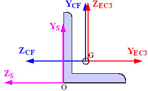
For the Eurocode 3 axes system:
![]() The origin matches to the CivilFEM axes origin.
The origin matches to the CivilFEM axes origin.
![]() XEC3 axis coincides with CivilFEM
X-axis.
XEC3 axis coincides with CivilFEM
X-axis.
![]() YEC3 axis is the relevant axis for
bending and its orientation is defined by the user (in steel check process).
YEC3 axis is the relevant axis for
bending and its orientation is defined by the user (in steel check process).
![]() ZEC3 axis is perpendicular to the
plane defined by X and Y axis, to ensure a right-handed system.
ZEC3 axis is perpendicular to the
plane defined by X and Y axis, to ensure a right-handed system.
To define this reference system, the user must indicate which direction of the CivilFEM axis (-Z, -Y, +Z or +Y) coincides with the relevant axis for positive bending. The user may define this reference system when checking according to this code. In conclusion, the code reference system coincides with that of CivilFEM, but it is rotated a multiple of 90 degrees, as shown in table below.
|
Relevant Axis for Bending in CivilFEM Reference System |
Angle of Rotation (clockwise) of Eurocode 3 Reference System respect to the CivilFEM Reference System |
|
- ZCF |
90 º (Default value) |
|
- YCF |
180 º |
|
+ ZCF |
270 º |
|
+ YCF |
0 º |
For Eurocode 3 checking, the following material properties are used:
|
Description |
Property |
|
Steel yield strength |
Fy(th) |
|
Ultimate strength |
Fu(th) |
|
Partial safety factors |
gM0 gM1 gM2 |
|
Elasticity modulus |
E |
|
Poisson coefficient |
n |
|
Shear modulus |
G |
Eurocode 3 considers the following data set for the section:
![]() Gross section data
Gross section data
![]() Net section data
Net section data
![]() Effective section data
Effective section data
![]() Data belonging to the section and plates class.
Data belonging to the section and plates class.
Gross section data correspond to the nominal properties of the cross-section. For the net section, only the area is considered. This area is calculated by subtracting the holes for screws, rivets and other holes from the gross section area. The area of holes is introduced within the structural steel code properties.
Effective section data and section and plates class data are obtained in the checking process according to the effective width method. For class 4 cross-sections, this method subtracts the non-resistance zones for local buckling. However, for cross-sections of a lower class, the sections are not reduced for local buckling.
In the following tables, the section data used in Eurocode 3 are shown:
|
Description |
Data |
|
Input data: 1.- Height 2.- Web thickness 3.- Flanges thickness 4.- Flanges width 5.- Distance between flanges 6.- Radius of fillet (Rolled shapes) 7.- Toe radius (Rolled shapes) 8.- Weld throat thickness (Welded shapes) 9.- Web free depth
|
H Tw Tf B Hi r1 r2 a d |
|
Output data |
(None) |
|
Description |
Data |
Reference axis |
|
Input data: 1.- Depth in Y 2.- Depth in Z 3.- Cross-section area 4.- Moments of inertia for torsion 5.- Moments of inertia for bending 6.- Product of inertia 7.- Elastic resistant modulus 8.- Plastic resistant modulus 9.- Radius of gyration 10.- Gravity center coordinates 11.- Extreme coordinates of the perimeter
12.- Distance between GC and SC in Y and in Z 13.- Warping constant 14.- Shear resistant areas 15.- Torsional resistant modulus 16.- Moments of inertia for bending about U, V 17.- Angle Y->U or Z->V
|
Tky tkz A It Iyy, Izz Izy Wely, Welz Wply, Wplz iy, iz Ycdg, Zcdg Ymin, Ymax, Zmin, Zmax Yms, Zms Iw Yws, Zws Xwt Iuu, Ivv a |
CivilFEM CivilFEM
CivilFEM CivilFEM CivilFEM CivilFEM CivilFEM CivilFEM Section Section
Section
CivilFEM CivilFEM Principal CivilFEM |
|
Output data: |
(None) |
|
The effective section depends on the section geometry and on the forces and moments that are applied to it. Consequently, for each element end, the effective section is calculated.
|
Description |
Data |
Reference axis |
|
Imput data: |
(None) |
|
|
Output data: 1.- Cross-section area 2.- Moments of inertia for bending 3.- Product of inertia 4.- Elastic resistant modulus 5.- Gravity center coordinates 6.- Distance between GC and SC in Y and in Z 7.- Warping constant 8.- Shear resistant areas |
Aeff Iyyeff, Izzeff Izyeff Wyeff, Wzeff Ygeff, Zgeff Ymseff, Zmseff Iw Yws, Zws |
CivilFEM CivilFEM CivilFEM Section Section
CivilFEM |
For Eurocode 3 checking, besides the section properties, more data are needed for buckling checks. These data are shown in the following table.
|
Description |
EN 1993-1-1:2005 |
|
Input data: |
|
|
1.- Unbraced length of member (global buckling). Length between lateral restraints (lateral-torsional buckling). |
L |
|
2.- Buckling effective length factors in XY, XZ planes YZ (Effective buckling length for plane XY =L*K XY ) (Effective buckling length for plane XZ =L*K XZ ). |
K XY, K XZ |
|
3.- Lateral buckling factors, depending on the load and restraint conditions. |
C1, C2, C3 |
|
4.- Equivalent uniform moment factors for flexural buckling. |
CMy, CMz |
|
5.- Equivalent uniform moment factors for lateral-torsional buckling. |
CMLt |
|
6.- Effective length factor regarding the boundar conditions. |
K |
|
7.- Warping effective factor. |
KW |
The checking process includes the evaluation of the following expression:

![]()
Evaluation steps:
1. Read the loading check requested by the user.
2. Read the CivilFEM axis to be considered as the relevant axis for bending so that it coincides with the Y axis of Eurocode 3. In CivilFEM, by default, the principle bending axis that coincides with the +Y axis of Eurocode 3 is the –Z.
3. The following operations are necessary for each selected element:
a. Obtain material properties of the element stored in CivilFEM
database and calculate the rest of the properties needed for checking:
Properties obtained from CivilFEM database:
Calculated properties:
Epsilon, material coefficient:
![]()
b. Obtain the cross-section data corresponding to the element.
c. Initialize values of the effective cross-section.
d. Initialize reduction factors of section plates and the rest of plate parameters necessary for obtaining the plate class.
e. If necessary for the type of check (check for buckling), calculate the critical forces and moments of the section for buckling: elastic critical forces for the XY and XZ planes and elastic critical moment for lateral-torsional buckling. (See section: Calculation of critical forces and moments).
f.
Obtain internal forces and moments: ![]() ,
, ![]() ,
, ![]() ,
, ![]() ,
, ![]() ,
, ![]() within the section.
within the section.
g. Specific section checking according to the type of external load. The specific check includes:
1. If necessary, selecting the forces and moments considered for the determination of the section class and used for the checking process.
2. Obtaining the cross-section class and calculating the effective section properties.
3. Checking the cross-section according to the external load and its class by calculating the check criterion.
h. Store the results.
Sections, according to Eurocode 3, are made up by plates. These plates can be classified according to:
1. Plate function: webs and flanges in Y and Z axis, according to the considered relevant axis of bending.
2. Plate union condition: internal plates or outstand plates.
For sections included in the program libraries, the information above is defined for each plate. CivilFEM classifies plates as flanges or webs according to their axis and provides the plate union condition for each end. Ends can be classified as fixed or free (a fixed end is connected to another plate and free end is not).
For checking the structure for safety, Eurocode 3 classifies sections as one of four possible classes:
|
Class 1 |
Cross-sections which can form a plastic hinge with the rotation capacity required for plastic analysis. |
|
Class 2 |
Cross-sections which can reach their plastic moment resistance, but have limited rotation capacity. |
|
Class 3 |
Cross-sections for which the stress in the extreme compression fiber of the steel member can reach the yield strength, but local buckling is liable to prevent the development of the plastic moment resistance. |
|
Class 4 |
Cross-sections for which it is necessary to make explicit allowances for the effects of local buckling when determining their moment resistance or compression resistance. |
The cross-section class is the highest (least favorable) class of all of its elements: flanges and webs (plates). First, the class of each plate is determined according to the limits of Eurocode 3. The plate class depends on the following:
1. The geometric width to thickness ratio with the plate width properly corrected according to the plate and shape type.
GeomRat = Corrected_Width / thickness
The width correction consists of subtracting the zone that does not contribute to buckling resistance in the fixed ends. This zone depends on the shape type of the section. Usually, the radii of the fillet in hot rolled shapes or the weld throats in welded shapes determine the deduction zone. The values of the corrected width that CivilFEM uses for each shape type include:
· Welded Shapes:
Double T section:
Internal webs or flanges:
Corrected width = d
d Web free depth
Outstand flanges:
|
Corrected width |
|
Where:
|
B |
Flanges width |
|
Tw |
Web thickness |
|
|
Radius of fillet |
T section:
Internal webs or flanges:
Corrected width = d
Outstand flanges:
Corrected width = B/d
C section:
Internal webs or flanges:
Corrected width = d
Outstand flanges:
|
Corrected width |
B – |
L section:
Corrected width
= ![]()
![]() Angle flange
width
Angle flange
width
Box section:
Internal webs:
Corrected width = H
H Height
Internal flanges:
Corrected
width ![]()
![]() Web thickness
Web thickness
Circular hollow section
Corrected width = H
· Rolled Shapes:
Double T section:
Internal webs or flanges:
Corrected width = d
d Web free depth
Outstand flanges:
Corrected width = B/2
B Flanges width
T Section:
Internal webs or flanges:
Corrected width = d
Outstand flanges:
Corrected width = B/2
C Section:
Internal webs or flanges:
Corrected width = d
Outstand flanges:
Corrected width = B
L Section:
Corrected width
= ![]()
![]() Angle flange
width
Angle flange
width
Box section:
Internal webs:
Corrected width = d
Internal flanges:
Corrected
width ![]()
![]() Flanges
thickness
Flanges
thickness
Pipe section:
Corrected width = H
2.
The limit listed below for width to thickness
ratio. This limit depends on the material parameter e and the normal stress
distribution in the plate section. The latter value is given by the following
parameters: a, ![]() and k0,
and the plate type, internal or outstand; the outstand case depends on if the
free end is under tension or compression.
and k0,
and the plate type, internal or outstand; the outstand case depends on if the
free end is under tension or compression.
Limit
(class) ![]()
![]()
![]()
where:
|
a |
Compressed length / total length |
|
y |
|
|
|
Buckling factor |
|
|
The higher stress in the plate ends. |
|
|
The lower stress in the plate ends. |
A linear stress distribution on the plate is assumed.
The procedure to determine the section class is as follows:
1. Obtain stresses at first plate ends from the stresses applied on the section, properly filtered according to the check type requested by the user.
2.
Calculate the parameters: a, ![]() and k0
and k0
For internal plates:
|
|
ENV 1993-1-1:1992 |
EN 1993-1-1:2005 |
|
|
|
|
|
|
|
|
|
|
|
|
|
|
|
|
For outstand plates with an absolute value of the stress at the free end greater than the corresponding value at the fixed end:
For ![]()
![]()
For ![]()
![]() = infinite
= infinite
For outstand plates with an absolute value of the stress at the free end lower than the corresponding value at the fixed end:
For ![]()
![]()
For ![]()
![]()
For ![]()
![]() = infinite
= infinite
Cases in which ![]() infinite are
not included in Eurocode 3. With these cases, the plate is considered to be
practically in tension and it will not be necessary to determine the class.
These cases have been included in the program to avoid errors, and the value
infinite are
not included in Eurocode 3. With these cases, the plate is considered to be
practically in tension and it will not be necessary to determine the class.
These cases have been included in the program to avoid errors, and the value ![]() has been adopted because the resultant plate class is 1 and the
plate reduction factor is r = 1 (the same values as if the whole
plate was in tension). The reduction factor is used later in the effective
section calculation.
has been adopted because the resultant plate class is 1 and the
plate reduction factor is r = 1 (the same values as if the whole
plate was in tension). The reduction factor is used later in the effective
section calculation.
3.
Obtain the limiting proportions as functions of:
a, ![]() and k0 and
the plate characteristics (internal, outstand: free end in compression or
tension).
and k0 and
the plate characteristics (internal, outstand: free end in compression or
tension).
EN 1993-1-1:2005:
Internal plates:
|
|
for |
|
|
for |
|
|
for |
|
|
for |
|
|
for |
|
|
for |
Outstand plates, free end in compression:
|
|
|
|
|
|
|
|
Outstand plates, free end in tension:
|
|
|
|
|
|
Above is the general equation used by the program to obtain the limiting proportions for determining plate classes. In addition, plates of Eurocode 3 may be checked according to special cases.
For example:
In sections totally compressed:
a= 1; ![]() = 1 for all plates
= 1 for all plates
In sections under pure bending:
a = 0.5; ![]() = -1 for the web
= -1 for the web
a = 1; ![]() = 1 for compressed
flanges
= 1 for compressed
flanges
4. Obtain the plate class:
|
If |
|
GeomRat |
< Limit(1) |
Plate Class = 1 |
|
If |
Limit(1) ≤ |
GeomRat |
< Limit(2) |
Plate Class = 2 |
|
If |
Limit(2) ≤ |
GeomRat |
< Limit(3) |
Plate Class = 3 |
|
If |
Limit(3) ≤ |
GeomRat |
|
Plate Class = 4 |
Repeat these steps (1,2,3,4) for each section plate.
5.
Assign of the highest class of the plates to the
entire section.
In tubular sections, the section class is directly determined as if it were a
unique plate, with GeomRat and the Limits calculated as follows:
6. GeomRat = outer diameter/ thickness.
![]()
![]()
![]()
For class 4 sections, the section resistance is reduced, using the effective width method.
For each
section plate, the effective lengths at both ends of the plate and the
reduction factors ![]() and
and ![]() are calculated.
These factors relate the length of the effective zone at each plate end to its
width.
are calculated.
These factors relate the length of the effective zone at each plate end to its
width.
Effective_length_end 1 = ![]()
Effective_length_end 2 = ![]()
The following formula from Eurocode 3 has been implemented for this process:
![]()
1. Internal plates:
For ![]() (Both ends
compressed)
(Both ends
compressed)

![]()
![]()
![]()
![]()
![]()
![]() corrected plate width
corrected plate width
plate_width = real plate width
For ![]() (end 1 in
compression and end 2 in tension)
(end 1 in
compression and end 2 in tension)

![]()
![]()
![]()
![]()
![]()
2. Outstand plates:
For ![]() (Both ends in
compression: end 1 fixed, end 2 free)
(Both ends in
compression: end 1 fixed, end 2 free)

![]()
![]()
![]()
For ![]() (end 1 fixed and in
tension, end 2 free and in compression)
(end 1 fixed and in
tension, end 2 free and in compression)

![]()
![]()
![]()
For ![]() (end 1 fixed and in
compression, end 2 free and in tension)
(end 1 fixed and in
compression, end 2 free and in tension)

![]()
![]()
![]()
If end 2 is the fixed end, the
values ![]() and
and ![]() are switched.
are switched.
The global reduction factor r is obtained by as follows:
EN 1993-1-1:2005:
For internal compression elements
For ![]()

For ![]()
![]()
For outstands compression elements:
For ![]()

For ![]()
![]()
Both Eurocode define as the plate slendernesss given by:

where:
![]() = corrected
plate width
= corrected
plate width
t = relevant thickness
e = material parameter
![]() = buckling factor
= buckling factor
To determine effective section properties, three steps are followed:
1.
Effective widths of flanges are calculated from factors α and ![]() these factors are
determined from the gross section properties. As a result, an intermediate
section is obtained with reductions taken in the flanges only.
these factors are
determined from the gross section properties. As a result, an intermediate
section is obtained with reductions taken in the flanges only.
2.
The resultant section properties are obtained
and factors α and ![]() are calculated
again.
are calculated
again.
3. Effective widths of webs are calculated so that the finalized effective section is determined. Finally, the section properties are recalculated once more.
The recalculated section properties are included in the effective section data table. Checking can be accomplished with the gross, net or effective section properties, according to the section class and checking type.
Each checking type follows a specific procedure that will be explained in the following sections.
Corresponds to chapter 6.2.3 in EN 1993-1-1:2005.
1. Forces and moments selection.
The forces and moments considered for this checking type are:
![]() = FX Design value
of the axial force (positive if tensile, element not processed if compressive).
= FX Design value
of the axial force (positive if tensile, element not processed if compressive).
2.
Class definition and effective section
properties calculation.
For this checking type, the section class is always 1 and the considered
section is either the gross or net section.
3.
Criteria calculation.
For members under axial tension, the general criterion Crt_TOT is
checked at each section. This criterion coincides with the axial criterion Crt_N.
![]()
where ![]() is the design tension resistance of the cross-section, taken as the smaller
value of:
is the design tension resistance of the cross-section, taken as the smaller
value of:
|
|
plastic design strength of the gross cross-section
|
|
|
|
ultimate design strength of the net cross-section |
|
4. Output results are written in the CivilFEM results file (.CRCF). Checking results: criteria and variables are described in the following table:
|
Result |
Concepts |
Description |
|
NED |
|
Design value of the tensile force (EN 1993-1-1:2005). |
|
NTRD |
|
Design tensile strength of the cross-section. |
|
CRT_N |
|
Axial criterion. |
|
CRT_TOT |
|
Eurocode 3 global criterion. |
|
NPLRD |
|
Design plastic strength of the gross cross-section. |
|
NURD |
|
Ultimate design strength |
Corresponds to chapter 6.2.4 in EN 1993-1-1:2005.
1. Forces and moments selection.
The forces and moments considered for this checking type are:
![]() = FX Design
value of the axial force (positive if compressive, element not processed if
tensile).
= FX Design
value of the axial force (positive if compressive, element not processed if
tensile).
2.
Class definition and effective section
properties calculation.
The section class is determined by the general processing of the section with
the previously selected forces and moments if the selected option is partial or
with all the forces and moments if the selected option is full. The entire
calculation process is accomplished with the gross section properties..
3.
Criteria calculation.
For members in axial compression, the general criterion Crt_TOT is
checked at each section. This criterion coincides with the axial criterion Crt_N:
![]()
where ![]() is the design compression resistance of the cross-section
is the design compression resistance of the cross-section
Class 1,2 or 3 cross-sections:
![]() design plastic
resistance of the gross section
design plastic
resistance of the gross section
Class 4 cross sections:
EN 1993-1-1:2005:
![]()
4. Output results written in the CivilFEM results file (.CRCF) . Checking results: criteria and variables are described at the following table.
|
Result |
Concepts |
Description |
|
NED |
|
Design axial force (EN 1993-1-1:2005). |
|
NCRD |
|
Design compression strength of the cross-section. |
|
CRT_N |
|
Axial criterion. |
|
CRT_TOT |
|
Eurocode 3 global criterion. |
|
CLASS |
|
Section Class. |
|
AREA |
|
Area of the section (Gross or Effective). |
Corresponds to chapter 6.2.5 in EN 1993-1-1:2005.
1.
Forces and moments selection.
The forces and moments considered for this checking type are:
![]() Design value of the bending moment along the relevant axis for
bending.
Design value of the bending moment along the relevant axis for
bending.
2.
Class definition and effective section
properties calculation.
The section class is determined by the general processing of the section with
the previously selected forces and moments if the selected option is partial or
with all the forces and moments if the selected option is full. The entire
calculation process is accomplished with the gross section properties.
3.
Criteria calculation.
For members subjected to a bending moment in the absence of shear force, the
following condition is checked at each section:
where:
![]()
![]() design value of the
bending moment
design value of the
bending moment
![]() design moment
resistance of the cross-section
design moment
resistance of the cross-section
Class 1 or 2 cross-sections:
![]()
Class 3 cross sections:
![]()
Class 4 cross sections:
EN 1993-1-1:2005:
![]()
4. Output results are written in the CivilFEM results file (.CRCF). Checking results: criteria and variables are described in the following table.
|
Result |
Concepts |
Description |
|
MED |
|
Design value of the bending moment (EN 1993-1-1:2005). |
|
MCRD |
|
Design moment resistance of the cross-section. |
|
CRT_M |
|
Bending criterion. |
|
CRT_TOT |
|
Eurocode 3 global criterion. |
|
CLASS |
|
Section Class. |
|
W |
|
Used section modulus (Elastic, Plastic or Effective). |
Corresponds to chapter 6.2.6 in EN 1993-1-1:2005.
1.
Forces and moments selection.
The forces and moments considered for this checking type are:
![]() Design
value of the shear force perpendicular to the relevant axis of bending.
Design
value of the shear force perpendicular to the relevant axis of bending.
2.
Class definition and effective section
properties calculation.
For this checking type, the section class is always 1 and the effective section
is the gross section.
3.
Criteria calculation.
With members under shear force, the following condition is checked at each
section:
![]()
where:
|
|
design value of the shear force |
|
|
design plastic shear resistance: |
|
|
shear area, obtained subtracting from the gross area the summation
of the flanges areas: |
Modifications
to the previous computation of ![]() are as follows:
are as follows:
· Rolled I and H sections, load parallel to web:
![]()
· Rolled channel sections, load parallel to web:
![]()
EN
1993-1-1:2005 specifies additional cases for the calculation of ![]() :
:
· Rolled I and H sections with load parallel to web:
![]() but not less
than η
but not less
than η ![]()
· Rolled T shaped sections with load parallel to web:
![]()
Where:
|
η |
η = 1.2 for steels with fy = 460 MPa η= 1.0 for steels with fy > 460 MPa |
|
|
Web depth |
|
|
Web thickness |
4. Output results are written in the CivilFEM results file (.CRCF). Checking results: criteria and variables are described in the following table.
|
Result |
Concepts |
Description |
|
VED |
|
Design value of the shear force (EN 1993-1-1:2005). |
|
VPLRD |
|
Design plastic shear resistance. |
|
CRT_S |
|
Shear criterion. |
|
CRT_TOT |
|
Eurocode 3 global criterion. |
|
CLASS |
|
Section Class. |
|
S_AREA |
Av |
Shear area. |
Corresponds to chapter 6.2.8 in EN 1993-1-1:2005.
1. Forces and moments selection.
The forces and moments considered for this checking type are:
![]() Design
value of the shear force perpendicular to the relevant axis of bending.
Design
value of the shear force perpendicular to the relevant axis of bending.
![]() Design value
of the bending moment along the relevant axis of bending.
Design value
of the bending moment along the relevant axis of bending.
2.
Class definition and effective section
properties calculation.
The section class is determined by the general processing of the sections with
the previously selected forces and moments if the selected option is partial or
with all the forces and moments if the selected option is full. The entire
calculation is accomplished with gross section properties.
3.
Criteria calculation.
For members subjected to bending moment and shear force, the following
condition is checked at each section:
![]()
![]()
Where:
![]() design resistance
moment of the cross-section, reduced by the presence of shear.
design resistance
moment of the cross-section, reduced by the presence of shear.
The reduction for shear is applied if the design value of the shear force exceeds 50% of the design plastic shear resistance of the cross-section; written explicitly as:
![]()
The design resistance moment is obtained as follows:
EN 1993-1-1:2005:
a. For double T cross-sections with equal flanges, bending about the major axis:


![]()
b. For other cases the yield strength is reduced as follows:
![]()
Note: This reduction of the yield strength fy is applied to the entire section. Eurocode 3 only requires the reduction to be applied to the shear area, and therefore, it is a conservative simplification.
For both cases, ![]() is the smaller
value of either
is the smaller
value of either ![]() or
or ![]() .
.
![]() is the design moment resistance of the cross-section, calculated according
to the class.
is the design moment resistance of the cross-section, calculated according
to the class.
4. Output results are written in the CivilFEM results file (.CRCF). Checking results: criteria and variables are described in the following table.
|
Result |
Concepts |
Description |
|
MED |
|
Design value of the bending moment (EN 1993-1-1:2005). |
|
VED |
|
Design value of the shear force (EN 1993-1-1:2005). |
|
MVRD |
|
Reduced design resistance moment of the cross-section. |
|
CRT_BS |
|
Bending and Shear criterion. |
|
CRT_TOT |
|
Eurocode 3 global criterion. |
|
CLASS |
|
Section Class. |
|
S_AREA |
|
Shear area. |
|
W |
|
Used section modulus (Elastic, Plastic or Effective). |
|
VPLRD |
|
Design plastic shear resistance. |
|
RHO |
|
Reduction factor. |
Corresponds to chapter 6.2.9 in EN 1993-1-1:2005.
1.
Forces and moments selection.
The forces and moments considered for this checking type are:
|
|
Design value of the axial force. |
|
|
Design value of the bending moment along the relevant axis of bending. |
|
|
Design value of the bending moment about the secondary axis of bending. |
2.
Class definition and effective section
properties calculation.
The section class is determined by the general processing of the sections with
the previously selected forces and moments if the selected option is partial,
or with all the forces and moments if the selected option is full. These
calculations are accomplished with the gross section properties.
3.
Criteria calculation.
For members subjected to bi-axial bending and in absence of shear force, the
following conditions at each section are checked:
Class 1 and 2 sections:

This condition is equivalent to:
![]()

![]()
Where ![]() and
and ![]() are the design moment resistance of the cross-section, reduced by the
presence of the axial force:
are the design moment resistance of the cross-section, reduced by the
presence of the axial force:


Where a and b are constants, which may take the following values:
For I and H sections:
a = 2 and b =5n ![]()
For circular tubes:
a = 2 and b =2
For rectangular hollow sections:
![]()
but ![]()
For solid rectangles and plates (the rest of sections):

Furthermore, the code specifies that in the case of rolled shapes for I or H sections or other sections with flanges, it is not necessary to reduce the design plastic strength for bending around the y-y axis due to the axial force if the following two conditions are fulfilled:
![]()
![]()
(if it does not reach half the tension strength of the web)
The same is applicable for bending around the z-z axis due to the axial force. There is no reduction when the following condition is fulfiled:
![]()
In absence of ![]() , the
previous check can be reduced to:
, the
previous check can be reduced to:

Condition equivalent to:

Class 3 sections (without holes for fasteners):

Condition equivalent to:
Crt_TOT = Crt_N + Crt_My + Crt_Mz £ 1


Where ![]() is the elastic resistant modulus about the y axis and
is the elastic resistant modulus about the y axis and ![]() is the elastic resistant modulus about the z axis.
is the elastic resistant modulus about the z axis.
In absence of ![]() , the above
criterion becomes:
, the above
criterion becomes:

Which is equivalent to:
Crt_TOT = Crt_N + Crt_My £ 1

Class 4 sections:

Condition equivalent to:
Crt_TOT = Crt_N + Crt_My + Crt_Mz £ 1


Where:
|
|
effective area of the cross-section |
|
|
effective section modulus of the cross-section when subjected to a moment about the y axis |
|
|
effective section modulus of the cross-section when subjected to a moment about the z axis |
|
|
shift of the center of gravity along the y axis |
|
|
shift of the center of gravity along the z axis |
Without ![]() , the above
criterion becomes:
, the above
criterion becomes:

which is equivalent to:
Crt_TOT = Crt_N + Crt_My + Crt_Mz £ 1


4. Output results are written in the CivilFEM results file (.CRCF). Checking results: criteria and variables are described in the following table.
|
Result |
Concepts |
Description |
|
NED |
|
Design value of the axial force (EN 1993-1-1:2005). |
|
MYED |
|
Design value of the bending moment about Y axis (EN 1993-1-1:2005). |
|
MZED |
|
Design value of the bending moment about Z axis (EN 1993-1-1:2005). |
|
NCRD |
|
Design compression resistance of the cross-section |
|
MNYRD |
|
Reduced design moment resistance of the cross-section about Y axis |
|
MNZRD |
|
Reduced design moment resistance of the cross-section about Z axis |
|
CRT_N |
|
Axial criterion |
|
CRT_MY |
|
Bending criterion along Y |
|
CRT_MZ |
|
Bending criterion along Z |
|
ALPHA |
α |
Alpha constant |
|
BETA |
β |
Beta constant |
|
CRT_TOT |
Crt_tot £ 1 |
Eurocode 3 global criterion |
|
CLASS |
|
Section Class |
|
AREA |
|
Area of the section utilized (Gross or Effective) |
|
WY |
|
Used section Y modulus (Elastic, Plastic or Effective) |
|
WZ |
|
Used section Z modulus (Elastic, Plastic or Effective) |
|
SIGXED |
|
Maximum longitudinal stress |
|
ENY |
|
Shift of the Z axis in Y direction |
|
ENZ |
|
Shift of the Y axis in Z direction |
|
USE_MY |
|
Modified design value of the bending moment about Y axis |
|
USE_MZ |
|
Modified design value of the bending moment about Z axis |
|
PARM_N |
n |
Parameter n |
Corresponds to chapter 6.2.10 in EN 1993-1-1:2005.
1. Forces and moments selection. The forces and moments considered for this checking type are:
|
|
Design value of the axial force. |
|
|
Design value of the shear force perpendicular to the secondary axis of bending. |
|
|
Design value of the shear force perpendicular to the relevant axis of bending. |
|
|
Design value of the bending moment about the relevant axis of bending. |
|
|
Design value of the bending moment about the secondary axis of bending. |
2.
Class definition and effective section
properties calculation.
The section class is determined by the general processing of the sections with
the previously selected forces and moments if the selected option is partial,
or with all the forces and moments if the selected option is full. The entire
calculation is accomplished with the gross section properties.
3.
Criteria calculation.
For members subjected to bending, axial and shear force, the same conditions of
the bending +axial force and bi-axial bending are checked at each section,
reducing the design plastic resistance moment for the presence of shear force.
The shear force effect is taken into account when it exceeds 50% of the design
plastic resistance of the cross-section. In this case, both the axial and the
shear force are taken into account.
The axial force effects are included as stated in the previous
section, and the shear force effects are taken into account considering a yield
strength for the cross-section, reduced by the factor (1-r), as follows:
![]()
where:
![]() for
for ![]()
|
|
for |
|
|
|
This yield strength reduction is selectively applied to the resistance of the cross-section along each axis, according to the previous conditions.
Note: The yield strength reduction is applied to the entire cross-section; however, Eurocode only requires the reduction to be applied to the shear area. Thus, it is a conservative simplification.
4.
Output results are written in the CivilFEM
results file (.CRCF). Checking results: criteria and variables are described in
the following table.
|
Result |
Concepts |
Description |
|
NED |
|
Design value of the axial force (EN 1993-1-1:2005). |
|
VZED |
|
Design value of the shear force (EN 1993-1-1:2005). |
|
VYED |
|
Design value of the shear force (EN 1993-1-1:2005). |
|
MYED |
|
Design value of the bending moment about Y axis (EN 1993-1-1:2005). |
|
MZED |
|
Design value of the bending moment about Z axis (EN 1993-1-1:2005). |
|
NCRD |
|
Design compression resistance of the cross-section. |
|
MNYRD |
|
Reduced design moment Y resistance of the cross-section. |
|
MNZRD |
|
Reduced design moment Z resistance of the cross-section. |
|
CRT_N |
|
Axial criterion. |
|
CRT_MY |
|
Bending Y criterion. |
|
CRT_MZ |
|
Bending Z criterion. |
|
ALPHA |
α |
Alpha constant. |
|
BETA |
β |
Beta constant. |
|
RHO_Y |
ρ |
Reduction factor for MNYRD. |
|
RHO_Z |
ρ |
Reduction factor for MNZRD. |
|
CRT_TOT |
Crt_tot £ 1 |
Eurocode 3 global criterion. |
|
AREA |
|
Used area of the section (Gross or Effective). |
|
WY |
|
Used section Y modulus (Elastic, Plastic or Effective). |
|
WZ |
|
Used section Z modulus (Elastic, Plastic or Effective). |
|
SIGXED |
|
Maximum longitudinal stress. |
|
ENY |
|
Shift of the Z axis in Y direction. |
|
ENZ |
|
Shift of the Y axis in Z direction. |
|
USE_MY |
|
Modified design value of the bending moment about Y axis. |
|
USE_MZ |
|
Modified design value of the bending moment about Z axis. |
|
SHY_AR |
|
Shear Y area. |
|
SHZ_AR |
|
Shear Z area. |
|
PARM_N |
n |
Parameter n. |
Corresponds to chapter 6.3.1 in EN 1993-1-1:2005.
1. Forces and moments selection.
The forces and moments considered in this checking type are:
|
|
Design value of the axial force (positive if compressive, otherwise element is not processed). |
2.
Class definition and effective section
properties calculation.
The section class is determined by the sections general processing with the
previously selected forces and moments if the selected option is partial, or
with all the forces and moments if the selected option is full. The entire
calculation is accomplished with the gross section properties.
3.
Criteria calculation.
When checking the buckling of compression members, the criterion is given by:
![]()
where:
|
|
Design buckling resistance. b = 1 for class 1, 2 or 3 sections. b = |
|
|
Reduction factor for the relevant buckling mode, the program does not consider the torsional or the lateral-torsional buckling. |
The c calculation in members of constant cross-section may be determined from:

![]()
where a is an imperfection factor that depends on the buckling curve. This curve depends on the cross-section type, producing the following values for a:
|
Section type |
Limits |
Buckling axis |
Steel fy |
Buckling curve |
a |
|
|
Rolled I |
h/b>1.2 and t |
y – y |
< 460 MPa |
a |
0.21 |
|
|
≥ 460 MPa |
a0 |
0.13 |
||||
|
Rolled I |
h/b>1.2 and t |
z – z |
< 460 MPa |
b |
0.34 |
|
|
≥ 460 MPa |
a0 |
0.13 |
||||
|
Rolled I |
h/b>1.2 and 40mm<t |
y – y |
< 460 MPa |
b |
0.34 |
|
|
≥ 460 MPa |
a |
0.21 |
||||
|
Rolled I |
h/b>1.2 and 40mm<t |
z – z |
< 460 MPa |
c |
0.49 |
|
|
≥ 460 MPa |
a |
0.21 |
||||
|
Welded I |
h/b |
y – y |
< 460 MPa |
b |
0.34 |
|
|
≥ 460 MPa |
a |
0.21 |
||||
|
Welded I |
h/b |
z – z |
< 460 MPa |
c |
0.49 |
|
|
≥ 460 MPa |
a |
0.21 |
||||
|
Rolled I |
t>100mm |
y – y |
< 460 MPa |
d |
0.76 |
|
|
≥ 460 MPa |
c |
0.49 |
||||
|
Rolled I |
t>100mm |
z – z |
< 460 MPa |
d |
0.76 |
|
|
≥ 460 MPa |
c |
0.49 |
||||
|
|
||||||
|
Welded I |
t |
y – y |
all |
b |
0.34 |
|
|
Welded I |
t |
z – z |
all |
c |
0.49 |
|
|
Welded I |
t >40mm |
y – y |
all |
c |
0.49 |
|
|
Welded I |
t >40mm |
z – z |
all |
d |
0.76 |
|
|
|
||||||
|
Pipes
|
Hot finished |
all |
< 460 MPa |
a |
0.21 |
|
|
≥ 460 MPa |
a0 |
0.13 |
||||
|
Cold formed |
all |
all |
c |
0.49 |
||
|
Reinforced box sections |
Thick weld: a/t>0.5 b/t<30 h/tw<30 |
all |
all |
c |
0.49 |
|
|
In other case |
all |
all |
b |
0.34 |
||
|
|
||||||
|
U, T, plate |
- |
all |
all |
c |
0.49 |
|
|
|
||||||
|
L |
- |
all |
all |
b |
0.34 |
|
![]()
![]()
Where ![]() is the elastic
critical force for the relevant buckling mode. (See section for Critical Forces
and Moments Calculation).
is the elastic
critical force for the relevant buckling mode. (See section for Critical Forces
and Moments Calculation).
In the case of angular sections, the buckling length will be taken as the highest among the buckling lengths on the Y and Z axis.
4. The elastic critical axial forces are calculated in the planes XY (Ncrxy) and XZ (Ncrxz) and the corresponding values of cxy and cxz , and the correspondent to the principal axis Ncru and Ncrv and the values for cu and cv taking the smaller one as the final value for c.
![]()
5. Output results are written in the CivilFEM results file (.CRCF). Checking results: criteria and variables are described in the following table.
|
Result |
Concepts |
Description |
|
NED |
|
Design value of the compressive force (EN 1993-1-1:2005). |
|
NBRD |
|
Design buckling resistance of a compressed member. |
|
CRT_CB |
|
Compression buckling criterion. |
|
CRT_TOT |
|
Eurocode 3 global criterion. |
|
CHI |
|
Reduction factor for the relevant buckling mode. |
|
BETA_A |
|
Ratio of the used area to gross area. |
|
AREA |
A |
Area of the gross section. |
|
CHI_Y |
|
Reduction factor for the relevant My buckling mode. |
|
CHI_Z |
|
Reduction factor for the relevant Mz buckling mode. |
|
CHI_V |
|
Reduction factor for the principal axis V. |
|
CHI_U |
|
Reduction factor for the principal axis U. |
|
CLASS |
|
Section Class. |
|
PHI_Y |
|
Parameter Phi for bending My. |
|
PHI_Z |
|
Parameter Phi for bending Mz. |
|
PHI_V |
|
Parameter Phi for the principal axis V. |
|
PHI_U |
|
Parameter Phi for the principal axis U. |
|
LAM_Y |
|
Non-dimensional reduced slenderness for bending My. |
|
LAM_Z |
|
Non-dimensional reduced slenderness for bending Mz. |
|
LAM_V |
|
Non-dimensional reduced slenderness for the principal axis V. |
|
LAM_U |
|
Non-dimensional reduced slenderness for the principal axis U. |
|
NCR_Y |
|
Elastic critical force for the relevant My buckling mode. |
|
NCR_Z |
|
Elastic critical force for the relevant Mz buckling mode. |
|
NCR_V |
|
Elastic critical force for the principal axis V. |
|
NCR_U |
|
Elastic critical force for the principal axis U. |
|
ALP_Y |
|
Imperfection factor for bending My. |
|
ALP_Z |
αz |
Imperfection factor for bending Mz. |
Corresponds to chapter 6.3.2 in EN 1993-1-1:2005.
1.
Forces and moments selection.
The forces and moments considered for this checking type are:
|
|
Design value of the bending moment about the relevant axis of bending. |
2.
Class definition and effective section
properties calculation.
The section class is determined by the general processing of sections with the
previously selected forces and moments if the selected option is partial, or
with all the forces and moments if the selected option is full. The entire
calculation is accomplished with the gross section properties.
3.
Criteria calculation.
When checking for lateral-torsional buckling of beams, the criterion shall be
taken as:
![]() à
à ![]()
where:
|
|
Design buckling resistance moment of a laterally unrestrained
beam. bw = 1 for class 1and 2 sections. bw = bw = |
|
cLT |
Reduction factor for lateral-torsional buckling. |
The value of cLT is calculated as:

![]()
![]()
Where:
|
|
is the imperfection factor for lateral-torsional buckling:
|
||||||||||||||||
|
|
is the elastic critical moment for lateral-torsional buckling.
|
4. Output results are written in the CivilFEM results file (.CRCF). Checking results: criteria and variables are described in the following table.
|
Result |
Concepts |
Description |
|
MED |
|
Design value of the bending moment (EN 1993-1-1:2005). |
|
MBRD |
|
Buckling resistance moment of a laterally unrestrained beam. |
|
CRT_LT |
|
Lateral-torsional buckling criterion. |
|
CRT_TOT |
|
Eurocode 3 global criterion. |
|
CLASS |
|
Section Class. |
|
CHI_LT |
|
Reduction factor for lateral-torsional buckling. |
|
BETA_W |
|
Ratio of the used modulus to plastic modulus. |
|
WPL |
|
Plastic modulus. |
|
PHI_LT |
|
Parameter Phi for lateral-torsional buckling. |
|
LAM_LT |
|
Non-dimensional reduced slenderness. |
|
MCR |
Mcr |
Elastic critical moment for lateral-torsional buckling. |
|
ALP_LT |
|
Imperfection factor for lateral-torsional buckling. |
Corresponds to chapter 6.3.3 in EN 1993-1-1:2005.
1.
Forces and moments selection.
The forces and moments considered in this checking type are:
|
|
Design value of the axial compression (positive if compressive, otherwise element not processed if tensile). |
|
|
Design value of the bending moment about the relevant axis of bending. |
|
|
Design value of the bending moment about the secondary axis of bending. |
2.
Class definition and effective section
properties calculation.
The section class is determined by the general processing of sections with the
previously selected forces and moments if the selected option is partial, or
with all the forces and moments if the selected option is full. The entire
calculation is accomplished with the gross section properties.
3. Criteria calculation.
EN 1993-1-1:2005 and Annex B (method 2)
The following criterion will always be calculated:
![]()
Crt_1 = Crt_N1 + Crt_My1 + Crt_Mz1 £ 1
Elements without torsional buckling:
![]()
Elements which may have torsional buckling:
![]()
à Crt_2 = Crt_N2 + Crt_My2 + Crt_Mz2 £ 1
à Crt_TOT = Max (Crt_1, Crt_2)
Where:
|
|
Axial force criterion 1. |
|
|
Bending moment criterion for principal axis 1. |
|
|
Bending moment criterion for secondary axis 1 |
|
Crt_TOT1 |
General criterion 1. |
|
|
Axial force criterion 2. |
|
|
Bending moment criterion 2 for principal axis without torsional buckling |
|
|
Bending moment criterion 2 for principal axis when torsional buckling is considered. |
|
|
Bending moment criterion 2 for secondary axis. |
|
Crt_TOT2 |
Criterion 2 |
|
Crt_TOT=max (Crt_TOT1, Crt_TOT2 ) |
Global criterion. |
Where:
![]()
![]()
(![]() when torsional buckling is not considered).
when torsional buckling is not considered).
![]() and
and ![]() are the reduction factors defined for the section
corresponding to the check for Buckling of Compression Members.
are the reduction factors defined for the section
corresponding to the check for Buckling of Compression Members.
![]() lateral buckling factor according to 6.3.2.2. Assumes the value of 1
for members not susceptible to torsional deformations.
lateral buckling factor according to 6.3.2.2. Assumes the value of 1
for members not susceptible to torsional deformations.
![]() and
and ![]() shifts
of the centroid of the effective area relative to the centre of gravity of the
gross section in class 4 members for y, z axes.
shifts
of the centroid of the effective area relative to the centre of gravity of the
gross section in class 4 members for y, z axes.
![]() ,
, ![]() and
and ![]() are equivalent uniform moment factors for flexural
bending. These factors are entered as member properties at member level. (See
are equivalent uniform moment factors for flexural
bending. These factors are entered as member properties at member level. (See ![]() and
and ![]() ). These factors may be taken from
Table B.3 from Annex B of code EN 1993-1-1:2005.
). These factors may be taken from
Table B.3 from Annex B of code EN 1993-1-1:2005.
Checking Parameters:
|
Class |
A |
|
|
|
|
|
|
|
1 |
A |
|
|
0.6 |
0.6 |
0 |
0 |
|
2 |
A |
|
|
0.6 |
0.6 |
0 |
0 |
|
3 |
A |
|
|
0.8 |
1 |
0 |
0 |
|
4 |
|
|
|
0.8 |
1 |
Depending on members and stresses |
Depending on members and stresses |
Interaction Factors:
|
Class |
Section type |
|
|
|
|
1 y 2 |
I, H |
|
|
|
|
RHS |
|
|||
|
3 y 4 |
All sections |
|
|
|
where:
![]() Limited slenderness values for y-y and z-z axes, less
than 1.
Limited slenderness values for y-y and z-z axes, less
than 1.
![]()
4. Output results are written in the CivilFEM results file (.CRCF). Checking results: criteria and variables are described in the following table.
|
Result |
Concepts |
Description |
|
NED |
|
Design value of the axial compression force. |
|
MYED |
|
Design value of the bending moment about Y axis. |
|
MZED |
|
Design value of the bending moment about Z axis. |
|
NBRD1 |
|
Design compression resistance of the cross-section. |
|
MYRD1 |
|
Reduced design moment resistance of the cross-section about Y axis. |
|
MZRD1 |
|
Reduced design moment resistance of the cross-section about Z axis. |
|
NBRD2 |
|
Design compression resistance of the cross-section. |
|
MYRD2 |
|
Reduced design moment resistance of the cross-section about Y axis. |
|
MZRD2 |
|
Reduced design moment resistance of the cross-section about Z axis. |
|
K_Y |
|
Parameter
|
|
K_Z |
|
Parameter
|
|
K_LT |
|
Parameter
|
|
CRT_N1 |
|
Axial criterion. |
|
CRT_MY1 |
|
Bending Y criterion. |
|
CRT_MZ1 |
|
Bending Z criterion. |
|
CRT_1 |
CRT_N1+CRT_MY1+CRT_MZ1 |
Criterion 1 |
|
CRT_N2 |
|
Axial criterion. |
|
CRT_MY2 |
|
Bending
Y criterion. K= |
|
CRT_MZ2 |
|
Bending Z criterion. |
|
CRT_2 |
CRT_N2+CRT_MY2+CRT_MZ2 |
Criterion 2 |
|
CRT_TOT |
Crt_tot £ 1 |
Eurocode 3 global criterion. |
|
CLASS |
|
Section Class. |
|
CHIMIN |
|
Reduction factor for the relevant buckling mode. |
|
CHI_Y |
|
Reduction factor for the relevant My buckling mode. |
|
CHI_Z |
|
Reduction factor for the relevant Mz buckling mode. |
|
CHI_LT |
|
Reduction factor for lateral-torsional buckling. |
|
AREA |
|
Used area of the section (Gross or Effective). |
|
WY |
|
Used section Y modulus (Elastic, Plastic or Effective). |
|
WZ |
|
Used section Z modulus (Elastic, Plastic or Effective). |
|
ENY |
|
Shift of the Z axis in Y direction. |
|
ENZ |
|
Shift of the Y axis in Z direction. |
|
NCR_Y |
|
Elastic critical force for the relevant My buckling mode. |
|
NCR_Z |
|
Elastic critical force for the relevant Mz buckling mode. |
|
MCR |
|
Elastic critical moment for lateral-torsional buckling. |
|
LAM_Y |
|
Non-dimensional reduced slenderness for bending My. |
|
LAM_Z |
|
Non-dimensional reduced slenderness for bending Mz. |
|
LAM_LT |
|
Non-dimensional reduced slenderness for lateral-torsional buckling. |
The critical forces and moments![]() ,
, ![]() and Mcr,
are needed for the different types of buckling checks. They are calculated
based on the following formulation:
and Mcr,
are needed for the different types of buckling checks. They are calculated
based on the following formulation:

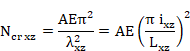
where:
|
|
Elastic critical axial force in plane XY. |
|
|
Elastic critical axial force in plane XZ. |
|
A |
Gross area. |
|
E |
Elasticity modulus. |
|
|
Member slenderness in plane XY. |
|
|
Member slenderness in plane XZ. |
|
|
Radius of gyration of the member in plane XY. |
|
|
Radius of gyration of the member in plane XZ. |
|
|
Buckling length of member in plane XY. |
|
|
Buckling length of member in plane XZ. |
The buckling length in both planes is the length between the ends restrained against lateral movement and it is obtained from the member properties, according to the following expressions:
![]()
![]()
where:
|
Cfbuckxy |
Buckling factor in plane XY. |
|
Cfbuckxz |
Buckling factor in plane XZ. |
For the calculation of the elastic critical moment for lateral-torsional buckling, Mcr, the following equation shall be used. This equation is only valid for uniform symmetrical cross-sections about the minor axis (Annex F, ENV 1993-1-1:1992). Eurocode 3 does not provide a method for calculating this moment in nonsymmetrical cross-sections or sections with other symmetry plane (angles, channel section, etc.).


where:
|
|
Elastic critical moment for lateral-torsional buckling. |
|
|
Factors depending on the loading and end restraint conditions. |
|
|
Effective length factors. |
|
E |
Elasticity modulus. |
|
|
Moment of inertia about the principal axis. |
|
|
Moment of inertia about the minor axis. |
|
L |
Length of the member between end restraints. |
|
G |
Shear modulus. |
|
|
|
|
|
Coordinate of the point of load application. By default the load
is applied at the center of gravity, therefore: |
|
|
Coordinate of the shear center. |
|
A |
Cross-section area. |
Factors C and k are read from the properties at structural element level.
The integration of the previous equation is
calculated as a summation extending to each plate. This calculation is
accomplished for each plate according to its ends coordinates: ![]() and
and ![]() and its thicknesses.
and its thicknesses.

where:
![]() = thickness of plate
i
= thickness of plate
i
dA = ![]() * dl
* dl
![]()
![]()
![]()
![]() = plate width
= plate width

For AISC 13th Edition checking, the following material properties are used:
|
Description |
Property |
|
Steel yield strength |
Fy(th) |
|
Ultimate strength |
Fu(th) |
|
Elasticity modulus |
E |
|
Poisson coefficient |
n |
|
Shear modulus |
G |
*th =thickness of the plate
AISC 13th Edition considers the following data set for the section:
- Gross section data
- Net section data
- Effective section data.
- Data belonging to the section and plates class.
Gross section data correspond to the nominal properties of the cross-section. For the net section, only the area is considered. This area is calculated by subtracting the holes for screws, rivets and other holes from the gross section area. (The area of holes is introduced within the structural steel code properties).
The effective section data and the section and plates class data are obtained in the checking process according to chapter B, section B4 of the code. This chapter classifies steel sections into three groups (compact, noncompact and slender), depending upon the width-thickness ratio and other mandatory limits.
The AISC 13TH Edition module utilizes the gross section data in user units and the CivilFEM axis or section axis as initial data. The program calculates the effective section data and the class data, and stores them in CivilFEM’s results file, in user units and in CivilFEM or section axis.
The section data used in AISC 13TH Edition are shown in the following tables:
|
Description |
Data |
|
Input data: 1.- Height 2.- Web thickness 3.- Flanges thickness 4.- Flanges width 5.- Distance between flanges 6.- Radius of fillet (Rolled shapes) 7.- Toe radius (Rolled shapes) 8.- Weld throat thickness (Welded shapes) 9.- Web free depth |
H Tw Tf B Hi r1 r2 a d |
|
Output data |
(None) |
|
Description |
Data |
Reference axes |
|
Input data: 1.- Depth in Y 2.- Depth in Z 3.- Cross-section area 4.- Moments of inertia for torsion 5.- Moments of inertia for bending 6.- Product of inertia 7.- Elastic resistant modulus 8.- Plastic resistant modulus 9.- Radius of gyration 10.- Gravity center coordinates 11.- Extreme coordinates of the perimeter
12.- Distance between GC and SC in Y and in Z 13.- Warping constant 14.- Shear resistant areas 15.- Torsional resistant modulus 16.- Moments of inertia for bending about U, V 17.- Angle Y->U or Z->V |
Tky tkz A It Iyy, Izz Izy Wely, Welz Wply, Wplz iy, iz Ycdg, Zcdg Ymin, Ymax, Zmin, Zmax Yms, Zms Iw Yws, Zws Xwt Iuu, Ivv a |
CivilFEM CivilFEM
CivilFEM CivilFEM CivilFEM CivilFEM CivilFEM CivilFEM Section Section
Section
CivilFEM CivilFEM Principal CivilFEM |
|
Output data: |
(None) |
|
|
Description |
Data |
|
Input data: 1.- Gross section area 2.- Area of holes |
Agross Aholes |
|
Output data: 1.- Cross-section area |
Anet |
The effective section depends upon the geometry of the section; thus, the effective section is calculated for each element and each of the ends of the element.
|
Description |
Data |
|
Input data: |
(None) |
|
Output data: 1.- Reduction factor 2.- Reduction factor 3.- Reduction factor |
Q Qs Qa |
For AISC 13th Edition checking, besides the section properties, more data are needed for bucling checks. These data are shown in the following table.
|
Description |
Data |
|
Input data: 1.- Unbraced length of member (global buckling) 2.- Effective length factors Y direction 3.- Effective length factors Z direction 4.- Effective length factors for torsional buckling 5.- Flexural factor relative to bending moment 6.- Length between lateral restraints |
L KY KZ KTOR Cb Lb |
|
Output data: 1.- Compression class 2.- Bending class |
CLS_COMP CLS_FLEX |
Necessary steps to conduct the different checks in CivilFEM are as follows:
a)
Obtain material properties corresponding to the
element stored in CivilFEM database and calculate the rest of the properties
needed for checking:
Properties obtained from CivilFEM database (materials):
|
Elasticity modulus |
E |
|
Poisson’s ratio |
|
|
Yield strength |
Fy (th) |
|
Ultimate strength |
Fu (th) |
|
Shear modulus |
G |
|
Thickness of corresponding plate |
th |
b) Obtain the cross-sectional data corresponding to the element.
c) Initiate the values of the plate’s reduction factors and the other plate’s parameters to determine its class.
d) Perform a check of the section according to the type of external load.
e) Results. In CivilFEM, checking results for each element end are stored in the results file .CRCF
Design shall be performed in accordance with:
![]()
Where:
|
|
Required strength (LRFD). |
|
|
Nominal strength. |
|
|
Resistance factor. |
|
|
Design strength |
Design shall be performed in accordance with:
![]()
Where:
|
|
Required strength (ASD) |
|
|
Nominal strength. |
|
|
Safety factor |
|
|
Allowable strength |
Steel sections are classified as compact,
noncompact or slender-element sections. For a section to qualify as compact its
flanges must be continuously connected to the web or webs and the
width-thickness ratios of its compression elements must not exceed the limiting
width-thickness ratios ![]() (see table B4.1 of
AISC 13th Edition). If the width-thickness ratio of one or more
compression elements exceeds
(see table B4.1 of
AISC 13th Edition). If the width-thickness ratio of one or more
compression elements exceeds ![]() but does not exceed
but does not exceed![]() , the section is
noncompact. If the width-thickness ratio of any element exceeds
, the section is
noncompact. If the width-thickness ratio of any element exceeds![]() , (see table B4.1 of
AISC 13th Edition), the section is referred to as a slender-element
compression section.
, (see table B4.1 of
AISC 13th Edition), the section is referred to as a slender-element
compression section.
Therefore, the code suggests different lambda values depending on if the element is subjected to compression, flexure or compression plus flexure.
The section classification is the worst-case scenario of all of its plates. Therefore, the class is calculated for each plate with the exception of pipe sections, which have their own formulation because it cannot be decomposed into plates. This classification will consider the following parameters:
a) Length of elements:
The program will define the element length (b or h) as the length of the plate (distance between the extreme points), except when otherwise specified.
b) Flange or web distinction:
To distinguish between flanges or webs, the program follows the criteria below:
Once the principal axis of bending is defined, the program will examine the plates of the section. Fields Pty and Ptz of the plates indicate if they behave as flanges, webs or undefined, choosing the correct one for the each axis. If undefined, the following criterion will be used to classify the plate as flange or web:
If ![]() (increments of end
coordinates) and flexure is in the Y axis, it will be considered a web; if not,
it will be a flange. The reverse will hold true for flexure in the Z-axis.
(increments of end
coordinates) and flexure is in the Y axis, it will be considered a web; if not,
it will be a flange. The reverse will hold true for flexure in the Z-axis.
· Hot rolled Steel Shapes:
Section I and C:
The length of the plate h will be taken as the value d for the section dimensions.
Section Box:
The length of the plate will be taken as the width length minus three times the thickness.
In order to check for compression it is necessary to determine if the element is stiffened or unstiffened.
- For stiffened elements:
![]()
![]()
Pipe sections
![]()
Box sections
![]()
![]()
- Unstiffened elements:
![]()
![]()
Angular sections
![]()
Stem of T sections
![]()
The bending check is only applicable to very specific sections. Therefore, the slenderness factor is listed for each section:
· Section I and C:
![]()
![]()

|
|
69 MPa for hot rolled shapes (10 ksi) |
|
114 MPa for welded sections (16.5 ksi) |
![]() = minimum of (
= minimum of (![]() ) and (
) and (![]() ) where
) where ![]() and
and![]() are the
are the ![]() of flange and web
respectively.
of flange and web
respectively.
Flanges of rolled sections:
![]()
![]()
Flanges of welded sections:
![]()
![]()
Flange:
If 
![]()
If 
![]()
![]()
Always: ![]()
![]() is the compression
axial force (taken as positive). If in tension, it will be taken as zero.
is the compression
axial force (taken as positive). If in tension, it will be taken as zero.
· Pipe section:
![]()
![]()
Box section:
Flanges of box section:
![]()
![]()
Flanges: the program distinguishes between the flange and web upon the principal axis chosen by the user.
If 
![]()
If 
![]()
![]()
Always: ![]()
![]()
· T section:
![]()
Stem: ![]()
Flanges: ![]()
The axial tension force must be taken as positive (if the tension force has a negative value, the element will not be checked)
Design tensile strength ![]() and the allowable
tensile strength
and the allowable
tensile strength ![]() , of tension
members, shall be the lower value of :
, of tension
members, shall be the lower value of :
a) yielding in the gross section:
![]()
![]()
![]()
b) rupture in the net section:
![]()
![]()
![]() = 2.00 (ASD)
= 2.00 (ASD)
Being:
|
|
Effective net area. |
|
|
Gross area. |
|
|
Minimum yield stress. |
|
|
Minimum tensile strength. |
The effective net area will be taken as ![]() – AHOLES.
The user will need to enter the correct value for AHOLES (the code
indicates that the diameter is 1/16th in. (2 mm) greater than the
real diameter).
– AHOLES.
The user will need to enter the correct value for AHOLES (the code
indicates that the diameter is 1/16th in. (2 mm) greater than the
real diameter).
The design compressive strength, ![]() ,and the allowable
compressive strength,
,and the allowable
compressive strength, ![]() , are determined as follows:
, are determined as follows:
The nominal compressive strength, ![]() , shall be the lowest
value obtained according to the limit states of flexural buckling, torsional
buckling and flexural-torsional buckling.
, shall be the lowest
value obtained according to the limit states of flexural buckling, torsional
buckling and flexural-torsional buckling.
![]()
![]()
This type of check can be carried out for compact sections as well as for noncompact or slender sections. These three cases adhere to the following steps:
Nominal compressive strength, ![]() :
:
![]() (E3-1)
(E3-1)

![]()
a) For : ![]()
![]() =
= 
b) for ![]()
![]()
Where:
|
|
Gross area of member. |
|
r |
Governing radius of gyration about the buckling axis. |
|
K |
Effective length factor. |
|
l |
Unbraced length. |
|
|
Elastic critical buckling stress |
Factor Q for compact and noncompact sections is always 1. Nevertheless, for slender sections, the value of Q has a particular procedure. Such procedure is described below:
Factor Q for slender sections:
For unstiffened plates, Qs must be calculated and for stiffened plates, Qa must be determined. If these cases do not apply (box sections or angular sections, for example), a value of 1 for these factors will be taken.
For circular sections, there is a particular procedure of calculating Q. Such procedure is described below:
· For circular sections, Q is:
![]()
![]()
Factor Qs:
If there are several plates free, the value of Qs is taken as the biggest value of all of them. The program will check the slenderness of the section in the following order:
· Angular
|
If |
|
|
|
If |
|
|
· Stem of T
|
If |
|
|
|
If |
|
|
· Rolled shapes
|
If |
|
|
|
If |
|
|
· Other sections
|
If |
|
|
|
If |
|
|
Where l is the element slenderness and
|
|
for I sections |
|
|
for other sections |
Factor Qa:
The calculation of factor Qa is an iterative process. Its procedure is the following:
1) An initial value of Q equal to Qs is taken.
2)
With this value ![]() is calculated.
is calculated.
3)
This ![]() value is taken to
calculate
value is taken to
calculate ![]()
4) For elements with stiffened plates, the effective width be is calculated.
5) With be the effective area is calculated.
6) With the value of the effective area, Qa is calculated, and the process starts again.
![]()
· For a box section
|
If |
|
|
· For other sections
|
If |
|
|
If it is not within those limits, ![]() = b
= b
With the ![]() values for each
plate, the part that does not contribute [t·(b‑
values for each
plate, the part that does not contribute [t·(b‑![]() )] is subtracted
from the area (where t is the plate thickness). Using this procedure, the
effective area is calculated.
)] is subtracted
from the area (where t is the plate thickness). Using this procedure, the
effective area is calculated.
Finally, with Qs and Qa, Q is calculated,
and ![]() is obtained.
is obtained.
Output results are written in the CivilFEM results file (.CRCF).
This type of check can be carried out for compact sections as well as for noncompact or slender sections. The steps for these three cases are as follows:
Nominal compressive strength,![]() :
:
![]()
c) for ![]()
![]()
(b) for ![]()
![]()
Where:

![]()
Factor Q for compact and noncompact sections is 1. Nevertheless, for slender sections, the Q factor has a particular procedure of calculation. Such procedure is equal to the one previously described.
The elastic stress for critical torsional
buckling or flexural-torsional buckling ![]() is calculated as
the lowest root of the following third degree equation, in which the axis have
been changed to adapt to the CivilFEM normal axis:
is calculated as
the lowest root of the following third degree equation, in which the axis have
been changed to adapt to the CivilFEM normal axis:
![]()
Where:
|
|
Effective length factor for torsional buckling. |
|
G |
Shear modulus (MPa). |
|
|
Warping constant (mm6). |
|
J |
Torsional constant (mm4). |
|
|
Moments of inertia about the principal axis (mm4). |
|
|
Coordinates of shear center with respect to the center of gravity (mm).
|


where:
|
A |
Cross-sectional area of member. |
|
l |
Unbraced length. |
|
|
Effective length factor, in the z and y directions. |
|
|
Radii of gyration about the principal axes. |
|
|
Polar radius of gyration about the shear center. |
In this formula, CivilFEM principal axes
are used. If the CivilFEM axes are the principal axes ±5º sexagesimal degrees, ![]() and
and ![]() are calculated with
respect to the Y and Z-axes of CivilFEM. If this is not the case (angular
shapes, for example) axes U and V will be used as principal axes, with U as the
axis with higher inertia.
are calculated with
respect to the Y and Z-axes of CivilFEM. If this is not the case (angular
shapes, for example) axes U and V will be used as principal axes, with U as the
axis with higher inertia.
The torsional inertia (Ixx in CivilFEM, J in AISC 13TH Edition) is calculated for CivilFEM sections, but not for captured sections. Therefore the user will have to introduce this parameter in the mechanical properties of CivilFEM.
Output results are written in the CivilFEM results file (.CRCF).
Chapter F is only applicable to members subject to simple bending about one principal axis.
The design flexural strength,![]() , and the allowable
flexural strength,
, and the allowable
flexural strength, ![]() , shall be
determined as follows:
, shall be
determined as follows:
For all provisions:![]() = 0.90 (LRFD)
= 0.90 (LRFD) ![]() = 1.67 (ASD)
= 1.67 (ASD)
Where ![]() is the lowest value
of four checks according to sections F2 through F12:
is the lowest value
of four checks according to sections F2 through F12:
a) Yielding
b) Lateral-torsional buckling
c) Flange local buckling
d) Web local buckling
The value of the nominal flexural strength with the following considerations:
|
Shape |
Limit State |
Mr |
Fcr |
l |
lp |
lr |
|
I, C loaded in the axis of higher inertia.
|
LTB |
|
|
|
|
|
|
FLB |
|
|
|
Class B4.1 |
Class B4.1 |
|
|
WLB |
|
N.A. |
|
Class B4.1 |
Class B4.1 |
|
Shape |
Limit State |
Mr |
Fcr |
l |
lp |
lr |
|
I, C loaded in the axis of lower inertia.
|
LTB |
N.A. |
N.A. |
N.A. |
N.A. |
N.A. |
|
FLB |
|
|
|
Class B4.1 |
Class B4.1 |
|
|
WLB |
N.A. |
N.A. |
N.A. |
N.A. |
N.A. |
|
Shape |
Limit State |
Mr |
Fcr |
l |
lp |
lr |
|
Box
|
LTB |
|
|
|
|
|
|
FLB |
|
|
|
Class B4.1 |
Class B4.1 |
|
|
WLB |
|
N.A. |
|
Class B4.1 |
Class B4.1 |
|
Shape |
Limit State |
Mr |
Fcr |
l |
lp |
lr |
Notes |
|
Pipe
|
LTB |
NA |
NA |
NA |
NA |
NA |
Limited by Class B4.1 |
|
FLB |
Slender:
Non-compact:
|
|
|
Class B4.1 |
Class B4.1 |
||
|
WLB |
NA |
NA |
NA |
NA |
NA |
|
Shape |
Limit State |
Mr |
Fcr |
l |
lp |
lr |
|
T, loaded in web plane
|
LTB |
|
N.A. |
N.A. |
N.A. |
N.A. |
|
FLB |
N.A. |
N.A. |
N.A. |
N.A. |
N.A. |
|
|
WLB |
N.A. |
N.A. |
N.A. |
N.A. |
N.A. |
Where:


(positive sign if the stem is under tension, negative if it is under compression)
In T sections: ![]() stem in tension;
stem in tension; ![]() stem in
compression.
stem in
compression.
For slender webs the nominal flexural
strength ![]() is the minimum of
the following checks:
is the minimum of
the following checks:
The first check uses the following formula:
![]()
where:
|
|
Section modulus referred to tension flange. |
|
|
Yield strength of tension flange. |
The second check uses the following formula:
![]()
where:

The critical stress depends upon different
slenderness parameters such as l, ![]() ,
, ![]() and
and ![]() in the following
way:
in the following
way:
|
For |
|
|
For |
|
|
For |
|
The slenderness values have to be calculated for the following limit states:
![]()


![]() (International System units)
(International System units)
![]() is the radius of
gyration of compression flange plus one third of the compression portion of the
web (mm).
is the radius of
gyration of compression flange plus one third of the compression portion of the
web (mm).
By default, the
program takes a conservative value of ![]() .
.
![]()


![]() (IS units)
(IS units)
where:
![]()
![]()
and
![]()
Between these two slenderness, the program will choose values the value that produces a lower critical stress.
Output results are written in the CivilFEM results file (.CRCF).
The design shear strength, ![]() , and the allowable
shear strength,
, and the allowable
shear strength, ![]() , shall be
determined as follows:
, shall be
determined as follows:
For all provisions: ![]() = 0.90 (LRFD)
= 0.90 (LRFD) ![]() = 1.67 (ASD)
= 1.67 (ASD)
According to the limit states of shear yielding
and shear buckling, the nominal shear strength, ![]() , of unstiffened webs is:
, of unstiffened webs is:
![]()
For webs of rolled I-shaped members with ![]() :
:
![]() = 1.00 (LRFD)
= 1.00 (LRFD) ![]() = 1.50 (ASD)
= 1.50 (ASD)
![]() = 1.0 (web shear
coefficient)
= 1.0 (web shear
coefficient)
For webs of all other doubly symmetric
shapes and singly symmetric shapes and channels ![]() is determined as
follows:
is determined as
follows:
![]() = 1.0
= 1.0
![]()
![]()
Where ![]() is the overall depth
times the web thickness.
is the overall depth
times the web thickness.
It is assumed that there are no stiffeners;
therefore, the web plate buckling coefficient ![]() will be calculated
as a constant equal to 5.0.
will be calculated
as a constant equal to 5.0.
Output results are written in the CivilFEM results file (.CRCF).
For this check, it is first necessary to
determine the value of Mn. This value comes into play in the checking of
formulas. The value of Mn, will be calculated in the same way as
members subjected to flexure; thus, the nominal flexure strength (![]() ) is the minimum of
four checks:
) is the minimum of
four checks:
1. Yielding
2. Lateral-torsional buckling
3. Flange local buckling
4. Web local buckling
In the case of having bending plus tension or bending plus compression, the interaction between flexure and axial force is limited by the following equations:
(a) For ![]()
![]() (H1-1a)
(H1-1a)
(b) For ![]()
![]() (H1-1b)
(H1-1b)
If the axial force is tension:
|
|
Required tensile strength (N). |
|
|
Available tensile strength (N):
|
|
|
Required flexural strength (N·mm). |
|
|
Available flexural strength (N·mm): Design: Allowable: |
|
y |
Strong axis bending. |
|
z |
Weak axis bending. |
|
|
Resistance factor for tension (Sect.D2) |
|
|
Resistance factor for flexure = 0.90 |
|
|
Safety factor for tension (Sect D2) |
|
|
Safety factor for flexure = 1.67 |
If the axial force is compression:
|
|
Required compressive strength (N). |
|
|
Available compressive strength (N): Design: Allowable: |
|
|
Required flexural strength (N·mm). |
|
|
Available flexural strength (N·mm): Design: Allowable: |
|
Y |
Strong axis of bending. |
|
Z |
Weak axis of bending. |
|
|
Resistance factor for compression =0.90 |
|
|
Resistance factor for flexure = 0.90 |
|
|
Safety factor for compression =1.67 |
|
|
Safety factor for flexure = 1.67 |
The following checks are carried out by CivilFEM:
If one of these checks do not meet the code requirements, it will not be possible to check the member under flexure plus tension / compression.
Output results are written in the CivilFEM results file (.CRCF).
The design torsional strength, fTTn , and the allowable torsional strength, Tn/ΩT , shall be the lowest value obtained according to the limit states of yielding under normal stress, shear yielding under shear stress or buckling, determined as follows:
![]() = 0.90 (LRFD)
= 0.90 (LRFD) ![]() = 1.67 (ASD)
= 1.67 (ASD)
· For the limit state of yielding, under normal stress:
![]()
· For the limit state of yielding, under shear stress:
![]()
· For the limit state of buckling:
![]()
-
Where ![]() is calculated
is calculated
Output results are written in the CivilFEM results file (.CRCF).
The British Standard BS 5950:2000 supersedes BS 5950:1985, which has been withdrawn. BS 5950:2000 is the British Standard for the structural use of steelwork in building, widely in use in regions which experience or have experienced British influence. The purpose of this manual is to define the reach and method of implementing this method within CivilFEM.
The types of analyses considered in this standard have been developed according to the ultimate limit state in agreement with the simple and continuous design methods. Semi-continuous design and experimental verification fall beyond the scope of this specification.
The applicable cross sections for checking procedures include rolled or welded sections subjected to axial forces, shear, and bending in 2D and 3D as well as solid sections subjected to the aforementioned forces.
The calculations made by CivilFEM correspond to the design guidelines of British Standard 5950:2000 Structural use of steelwork in building: Part 1. Code of practice for design – Rolled and welded sections.
With CivilFEM it is possible to accomplish the following checking and analysis types:
Checking of sections subjected to:
|
British Standard 5950 (2000) apt. 4.2 |
|
|
- Bending and Shear |
British Standard 5950 (2000) apt. 4.2 |
|
- Lateral Torsional Buckling |
British Standard 5950 (2000) apt. 4.3 |
|
- Axial Tension |
British Standard 5950 (2000) apt. 4.6 |
|
- Axial Compression |
British Standard 5950 (2000) apt. 4.7 |
|
- Axial Tension with Moments |
British Standard 5950 (2000) apt. 4.8.2 |
|
- Axial Compression with Moments |
British Standard 5950 (2000) apt. 4.8.3 |
With performing checks according to BS 5950:2000, CivilFEM includes three different coordinate reference systems. All of these systems are right-handed:
1. CivilFEM Reference Axes (![]() ).
).
2.
Cross-Section Reference Axes (![]() ,
, ![]() ,
, ![]() ).
).
3.
BS 5950:2000 Reference Axes (Code Axes), (![]() ).
).

For the BS 5950:2000 axes axes system:
![]() The origin matches to the CivilFEM axes origin.
The origin matches to the CivilFEM axes origin.
![]() XEC3 axis coincides with CivilFEM
X-axis.
XEC3 axis coincides with CivilFEM
X-axis.
![]() YEC3 axis is the relevant axis for
bending and its orientation is defined by the user (in steel check process).
YEC3 axis is the relevant axis for
bending and its orientation is defined by the user (in steel check process).
![]() ZEC3 axis is perpendicular to the
plane defined by X and Y axis, to ensure a right-handed system.
ZEC3 axis is perpendicular to the
plane defined by X and Y axis, to ensure a right-handed system.
To define this reference system, the user must indicate which direction of the CivilFEM axis (-Z, -Y, +Z or +Y) coincides with the relevant axis for positive bending. The user may define this reference system when checking according to this code. In conclusion, the code reference system coincides with that of CivilFEM, but it is rotated a multiple of 90 degrees, as shown in table below.
BS 5950:2000 uses the following material properties in its checks:
|
Description |
Properties, symbol |
|
Yield strength |
|
|
Tensile strength |
|
|
Design strength |
py (table 9 of BS 5950-1:2000 and table 3 of EN10113-2:1993) |
|
Material strength factor |
|
|
Modulus of elasticity |
E = 205 kN/mm2 |
|
Shear Modulus |
|
|
Poisson’s ratio |
|
|
Coefficient of linear thermal expansion |
|
|
Effective net area coefficient |
|
|
Constant є |
|
The
code uses other safety factors (![]() ) which depend on the type of loads and which must be
used when performing load combinations.
) which depend on the type of loads and which must be
used when performing load combinations.
BS 5950:2000 considers the following data set for the cross section:
![]() Gross section data
Gross section data
![]() Net section data
Net section data
![]() Effective section data
Effective section data
![]() Data concerning the section and element class.
Data concerning the section and element class.
Gross section data correspond to the nominal properties of the cross-section.
From the net section, the net area and the effective net area are considered. The net area is calculated by subtracting the area of holes for screws, rivets and other holes from the gross section area, taking into account the deduction for fastener holes according to section 3.4.4 of the code (see figures 3 and 4 of the code). The area of holes is introduced within the structural steel code properties.
The effective net area is obtained from the
net area, multiplying it by a coefficient ![]() which depends on
type of steel used. This coefficient is calculated by the program and stored
together with the material properties.
which depends on
type of steel used. This coefficient is calculated by the program and stored
together with the material properties.
Effective section data are obtained in the checking process according to the effective width method (Sect. 3.6 of BS 5950:2000). This method discounts the non-resistance zones for local buckling in class 4 cross-sections. For cross-sections of a lower class, this method does not reduce the section because of local buckling.
As an alternative method for slender cross
sections calculation, a reduced design strength (![]() ) may be calculated
at which the cross section would be class 3 (section 3.6.5 of the code).
) may be calculated
at which the cross section would be class 3 (section 3.6.5 of the code).
Section and element class data are obtained using tables 11 and 12 of BS 5950:2000 (section 3.5.2). The classification of each element is based on its width to thickness ratio and according to section type (hot-rolled or welded), element type (web or flange) and position (internal or external element). CivilFEM assumes the section class as the largest from all the elements (least favorable).
The initial required data for the BS 5950:2000 module includes the gross section data in user units and the CivilFEM axis or section axis (see the section corresponding to Reference axis in beam sections in Chapter 5 of this Manual). The data are then properly converted from the section’s axis into the BS 5950:2000 axis and the results are given in the code axis. The program calculates the effective and net section data and the class data and stores them into CivilFEM’s results file in user units and in the CivilFEM coordinate system.
The section data used in BS 5950:2000 is shown in the following tables:
I.- Section Dimensions
|
Description |
Data |
|
Input data: 1.- Height 2.- Web thickness 3.- Flanges thickness 4.- Flanges width 5.- Distance between flanges 6.- Radius of fillet (Rolled shapes) 7.- Toe radius (Rolled shapes) 8.- Weld throat thickness (Welded shapes) 9.- Web free depth |
H Tw Tf B Hi r1 r2 a d |
|
Output data |
(Nothing) |
I.- Gross Section Resistant Properties
|
Description |
Data |
|
Input: 1.- Area 2.- Moments of inertia for torsion 3.- Moments of inertia for bending 4.- Product of inertia 5.- Elastic resistant modulus 6.- Plastic resistant modulus 7.- Radius of gyration 8.- Coordinates of the center of gravity
9.- Distance between GC and SC in X and in Y 10.- Distance CG to shear center along Y axis 11.- Distance CG to shear center along X axis 12.- Warping Constant 13.- Shear resistant areas 14.- Torsional resistant modulus |
A It Ixx, Iyy Ixy Wx, Wy Wpx, Wpy ix, iy Ymn, Ymx, Xmn, Xmx Xm, Ym Ys Xs Iw Yws, Xws Zwt |
|
Output Data: 1.- Shear area for major axis (X) 2.- Sv parameter for major axis (X) 3.- Shear area for minor axis (Y) 4.- Sv parameter for minor axis (X) 5.- Critical shear strength of web panel for major axis 6.- Critical shear strength of web panel for minor axis 7.- Y coordinate of plastic center 8.- X coordinate of plastic center |
Avx Svx Avy Svy Vcrx Vcry Yp Xp |
|
* The section properties listed here in are related to the BS coordinate system (XBS, YBS, ZBS) |
|
III.- Net section data
|
Description |
Data |
|
Input data: AHOLES* |
|
|
Output data: 1.- Net area 2.- Effective net area |
Ant Aneff |
|
|
|
* Deduction for holes are introduced as a code property
IV.- Effective section data
|
Description |
Data |
|
Input data: None |
|
|
Output data: 1.- Effective Area 2.- Moments of inertia for torsion 3.- Moments of inertia for Y bending 4.- Moments of inertia for X bending 5.- Elastic resistant Y modulus 6.- Elastic resistant X modulus 7.- Plastic resistant Y modulus 8.- Plastic resistant X modulus |
Aeff It Iyyeff Ixxeff Wyeff Wxeff Wpyeff Wpxeff |
|
9.- Section class 10.- Web class for shear buckling |
Cls ClsAlm |
V.- Section element data
|
Description |
Data |
|
Input data: 1.- Number of elements 2.- Element type: flange or web (for the relevant axis of bending) 3.- Union condition at the ends: free or fixed 4.- Element thickness 5.- Coordinates of the extreme points of the element (using Section axes)
|
N Pltype Cp1, Cp2 t Yp1, Yp2, Zp1, Zp2 |
|
Output data: 6.- Element class 7.- Reduction factor (for class 4 section- alternative method) 8.- Web Class |
Cl fr Webclass |
For BS 5950:2000 check, besides the section properties, more data are needed for buckling checks. These data are shown in the following table.
|
Description |
Data |
Article |
|
Input data: 1.- Unbraced length of member 2.- Compression buckling factor for X axis 3.- Compression buckling factor for Y axis 4.- Lateral torsional buckling factor for X axis 5.- Lateral torsional buckling factor for Y axis 6.- Factors by which multiply “L” to found the length between restrictions in planes xz and yz, respectively 7.- Robertson Constant 8.- Equivalent uniform moment factor for major axis flexural bending 9.- Equivalent uniform moment factor for minor axis flexural bending 10.- Equivalent uniform moment factor for lateral torsional buckling 11.- Depth of the compression flanges lip 12.- Intermediate stiffeners depth 11.- CivilFEM Axis which is the X axis in BS 5950:2000 0: Not defined 1: -Z CivilFEM 2: +Y CivilFEM 3: +Z CivilFEM 4: -Y CivilFEM |
L Kcx Kcy Klty Cfbuckx, Cfbucky CteRob mx my mlt DL d/a CHCKAXIS |
Section 4.7.3 Section
4.7.3 Section 4.3.5
Appendix C.2 Section
4.8.3 Section
4.8.3 Section
4.3.6.6 Section 4.3.6.7 Section 4.4.5
|
The steps for the checking process are the following ones:
4. Read the checking type requested by the user.
5. Read the CivilFEM axis to be considered as the principal axis for bending, so that it coincides with the X-axis of BS5950. In CivilFEM, by default, the principal axis for bending that coincides with the +X axis of BS 5950:2000 is the –Z-axis.
6. The following operations are carried out for each selected element:
a.
Obtain material properties corresponding to the
element, stored in CivilFEM database, and calculate the rest of the properties
needed for checking:
Properties obtained from CivilFEM database:
|
Elasticity modulus |
E |
|
Poisson’s ratio |
|
|
Yield strength |
|
|
Ultimate strength |
|
|
Design strength |
|
|
Ke parameter |
|
|
Safety factor |
|
Calculated properties:
Shear Modulus:
![]()
Epsilon, material coefficient:
![]() (
(![]() in
in![]() )
)
b. Obtain the cross-section data corresponding to the element.
c. Determination of section class.
d. There are two calculation procedures for slender cross sections (class 4) that may be may chosen by the user:
1. Initialize reduction factors of section plates and the effective cross section properties calculation.
2. Calculate a reduced design strength that should be used in place of the nominal design strength (section 3.6.5 of the code).
e.
Obtain forces acting on the section (FX,![]() ).
).
f. Specific section checking according to the type of external load.
g. Writing of results, which will be stored in the results file .CRCF
According to BS 5950:2000, the sections are made up of different elements, which can be classified according to:
a) The way they work:
Webs and flanges in the X and Y axes, depending on which is the principal bending axis.
b) Their relation to the other elements:
Internal or outside elements
The sections of the shapes included in the program libraries contain this information for each element. CivilFEM classifies elements as either flange or web according to each axis and gives the element union condition at each end. The ends can be classified as fixed or free (i.e. an end is called fixed if it is in contact with another plate and free if it is not).
For checking the structure for safety, BS 5950:2000 classifies cross sections into four different classes to determine whether local buckling influences their capacity (section 3.5.2):
|
Class 1 |
Plastic cross sections are those in which a plastic hinge can be developed with sufficient rotation capacity to allow redistribution of moments within the structure. |
|
Class 2 |
Compact cross sections are those in which the full plastic moment capacity can be developed but local buckling may prevent development of a plastic hinge with sufficient rotation capacity to permit plastic design. |
|
Class 3 |
Semi-compact sections are those in which the stress at the extreme fibers can reach the design strength but local buckling may prevent the development of the full plastic moment. |
|
Class 4 |
Slender sections are those which contain slender elements subject to compression due to moment or axial load. Local buckling may prevent the stress in a slender section from reaching the design strength. |
The cross-section class is the highest (least favorable) class of its elements: flanges and webs. The class of each element is first determined according to the limits of tables 11 and 12 of BS 5950:2000. According to these tables, the class of an element depends on:
1.
The width to thickness ratio. The dimensions of
the elements (b, d, t, T) should be
taken as shown in Figure 5 of the code.
Rd = Width / Thickness
2. The limits of this ratio, according to the type of section, element (flange or web) and position (internal or outside). Elements that do not meet the limits for class 3 semi-compact are classified as class 4. The limits are the following (refer to figure 5 of the code for dimensions):
· Sections other than circular hollow sections (CHS) and rectangular hollow section (RHS):
|
Compression element |
Class 1 |
Class 2 |
Class 3 |
|
Outstand rolled flange Angle, compression due to bending |
|
|
|
|
Angle, axial compression |
0 |
0 |
y
|
|
Outstand welded flange |
|
|
|
|
Internal flange, compression due to bending |
|
|
|
|
Internal flange, axial compression |
0 |
0 |
|
|
Web of an I, H or box section, compression due to bending |
|
For
For |
|
|
Web of an I, H or box section, axial compression |
0 |
0 |
|
|
Web of a channel |
|
|
|
|
Stem of a T section, rolled or cut from a rolled I or H section |
|
|
|
· Circular hollow sections (CHS):
Circular hollow sections are classified as having only one element
and the width to thickness ratio (![]() ) is determined as
follows:
) is determined as
follows:
![]() D
= Diameter.
D
= Diameter.
t = Wall thickness.
|
|
Class 1 |
Class 2 |
Class 3 |
|
Compression due to bending |
|
|
|
|
Axial compression |
0 |
0 |
|
· Rectangular hollow sections hot finished (HF RHS):
|
Compression element |
Class 1 |
Class 2 |
Class 3 |
|
Flange, compression due to bending |
|
|
|
|
Flange, axial compression |
0 |
0 |
|
|
Web, compression due to bending |
|
|
|
|
Web, axial compression |
0 |
0 |
|
· Rectangular hollow sections cold formed (CF RHS):
|
Compression element |
Class 1 |
Class 2 |
Class 3 |
|
Flange, compression due to bending |
|
|
|
|
Flange, axial compression |
0 |
0 |
|
|
Web, compression due to bending |
|
|
|
|
Web, axial compression |
0 |
0 |
|
* The dimensions b and t are defined in figure 5 of the code.
Notes:
1. The classification of the elements according to the way they work (webs or flanges) is included in the program section library. In other cases the user can specify it or, by default, the program will automatically determine it as a function of the angle a with respect to the principal axis of bending, following the below criterion:
ForaWeb
ForaFlange
2.
Apart from the type of section, type and
position of the element, the limits of the width to thickness ratio also depend
on the material parameter and on the parameters ![]() and
and![]() , which translates into the following relationships
, which translates into the following relationships
a) For I or H-sections with equal flanges:
![]() with
with ![]()

b) For I or H-sections with unequal flanges:
The program deals with this type of sections as generic sections for
which the values of r1 and ![]() are the following:
are the following:
![]() = 1
= 1
![]() = 1
= 1
c) Rectangular hollow sections or welded box sections with equal flanges:
![]() with
with ![]()
Where:
|
|
Gross section area. |
|
|
Width of the compression flange. |
|
|
Width of the tension flange. |
|
d |
Web depth. |
|
|
Axial compression (negative for tension). |
|
|
Maximum compressive stress in the web (figure 7 of the code). |
|
|
Minimum compressive stress in the web (figure 7 of the code). |
|
|
Design strength of the flanges. |
|
|
Design strength of the web (but |
|
|
Thickness of the compression flange. |
|
|
Thickness of the tension flange. |
|
t |
Web thickness. |
3. The webs are also classified for shear buckling resistance according to the following criteria:
a.
For rolled sections with Rd![]()
b.
For welded sections with Rd![]()
In these cases, the shear buckling resistance should be checked according to the section 4.4.5 of the BS 5950:2000.
4.
Class 3 semi-compact sections are designed using
the effective plastic modulus
![]() according to
section 3.5.6 and followings of BS 5950:2000.
according to
section 3.5.6 and followings of BS 5950:2000.
BS 5950:2000 accepts two different procedures for designing slender cross sections.
a) Effective section properties calculation (Sections 3.6.2, 3.6.3, 3.6.4)
The local buckling resistance of class 4 slender cross sections is performed by adopting effective section properties. The width of the compression elements are reduced in such way that the effective width of a class 4 section will be the same as the maximum width for a class 3 section.
For outstand elements, the reduction is applied to its free end, and for internal elements, the reduction is applied to the non-effective zone, comprised of the central portion of the element with two equal portions of effective zone at the ends.
For each section element, the program
calculates two reduction factors
![]() and
and ![]() to determine the
effective width at each element end. These factors relate the width of the
effective zone at each end with the width of the plate.
to determine the
effective width at each element end. These factors relate the width of the
effective zone at each end with the width of the plate.
Effective_width_end1
= plate_![]()
Effective_ width _end 2 =
plate_![]()

Effective area calculation (![]() )
)
The effective area is determined from the effective cross section as shown in Figure 8a of the code (section 3.6.2.2).

Effective modulus calculation (![]() )
)
The effective modulus is determined from the effective cross section as shown in Figure 8b of the code (section 3.6.2.3).

For cross sections with slender webs, the effective modulus is determined from the effective cross section as shown in Figure 9 of the code (section 3.6.2.4).

For circular hollow sections, the effective modulus and the effective area is determined according to the section 3.6.6 of BS 5950:2000.
b) Alternative Method (section 3.6.5)
As an alternative to the method previously described, a reduced design strength ryr is calculated as if the cross section were a class 3 semi-compact. This reduced design strength is used in place of ry in the checks of section capacity and member buckling resistance. The reduction factor fr is calculated for each section 4 element according to the below expression:

![]()
Where:
|
b3 |
Limiting value for a class 3 section according to the tables 11 and 12 of the code. |
|
b |
Width to thickness ratio for each element. |
1.
Forces and moments selection
The forces and moments considered for this checking type are:
|
|
Design value of the shear force perpendicular to the relevant axis of bending. |
|
|
Design value of the bending moment along the relevant axis of bending. |
2. Class determination and calculation either of the effective section properties or the design strength reduction factor for slender sections (depending on the selected method).
3. Criteria calculation
In members subjected to bending moment and shear force, three conditions should be checked:
3.1. Shear checking (Article 4.2.3 of BS 5950:2000)
The first condition to be checked is the shear criteria at each section:
![]() à
à ![]()
Where:
|
|
Design value of the shear
capacity:
|
|
|
Design strength of the material. |
|
|
Shear area. |
Shear
Area Calculation (![]() )
)
According to section 4.2.3 the shear area is calculated as follows:
|
Shape |
Shear Area |
|
Rolled I, H and channel sections, load parallel to web. |
|
|
Welded I sections, load parallel to web. |
|
|
Solid bars and plates. |
|
|
Rectangular hollow sections, load parallel to webs. |
|
|
Welded box sections. |
|
|
Circular hollow sections. |
|
|
Any other case. |
|
where:
|
t |
Total web thickness. |
|
B |
Breadth. |
|
D |
Overall depth. |
|
d |
Depth of the web. |
|
A |
Area of the section. |
|
|
Area of the rectilinear element of the section which has the largest dimension in the direction parallel to the load:
|
In the case of biaxial bending, it is necessary to consider both shear areas, perpendicular to both the Standard’s X- and Y-axis.
3.2. Shear buckling resistance of thin webs (Article 4.4.5)
The shear buckling resistance should be checked if the ratio d/t of the web exceeds 70·e for a rolled section or 62·e for welded sections. It should satisfy the following criterion:
![]()
![]()
Where:
|
|
Shear buckling resistance (summation extended to all section webs). |
|
|
Critical shear strength. |
|
d |
Depth of the web. |
|
t |
Thickness of the web. |
The critical shear strength is obtained following the Appendix H.1 of the code
where ![]() and a is the distance between stiffeners. The ratio
and a is the distance between stiffeners. The ratio
d/a may be introduced by the user. By default, d/a = 1.
If the web of the section
is not slender (d/t < 70·e for rolled sections and
d/t < 62·e for welded sections):
Crt_PV = 0
3.3. Bending moment check
Besides the shear checking, the following condition at each section is checked (Article 4.2.5 of BS 5950:2000):
![]() à
à ![]()
![]()
Where:
|
|
Moment capacity. |
|
Fr |
Stress reduction factor (only for the alternative method for slender sections). |
|
|
Bending resistant modulus. |
The reduction of the bending resistant modulus due to the effect of shear load is only applied if the shear load is above 60% of shear capacity of the section:
![]()
The bending resistant modulus is obtained by the following expressions:
1. If ![]()
a. For plastic or compact sections:
![]()
b. For semi-compact sections:
![]()
c. For slender sections:
![]()
2. If ![]()
a. For plastic or compact sections:
![]()
b. For semi-compact sections:
![]()
c. For slender sections:
![]()

Where:
|
Z |
Elastic resistant modulus of the section. |
|
|
Effective elastic modulus. |
|
S |
Plastic resistant modulus of the section. |
|
|
Effective plastic modulus. |
|
|
Plastic reduced modulus due to the effect of shear force. |
Sv Parameter Calculation
The ![]() calculation is done
following the expression below:
calculation is done
following the expression below:
![]()
Where:
|
S |
Plastic resistant modulus of the section: S |
|
|
Plastic modulus of the section remaining after deduction of the shear area: |
4. Calculation of the total criterion:
CRT_TOT = Max (Crt_V, Crt_PV, Crt_M)
5. Output results are written in the CivilFEM results file (.CRCF). Checking results: criteria and variables are described in the following table:
|
Result |
Concepts |
Articles |
Description |
|
MX |
|
|
Design value of the bending moment |
|
MC |
|
4.2.5 |
Moment capacity |
|
FV |
|
|
Design value of the shear force |
|
PV |
|
4.2.3 |
Design value of the shear capacity |
|
CRT_V |
|
4.2.3 |
Shear criterion |
|
CRT_PV |
|
4.4.5 |
Buckling web criterion |
|
CRT_M |
|
4.2.5 |
Bending criterion |
|
CRT_TOT |
|
|
BS Global criterion |
|
CLASS |
|
3.5.2 |
Section class |
|
WEBCLASS |
|
3.5.2 |
Webs' Class |
|
MDF |
|
4.2.5 |
Plastic or elastic modulus of the section |
|
VW |
|
4.4.5 |
Shear buckling resistance |
1.
Forces and moments selection.
The forces and moments considered in this check are:
|
|
Design value of the bending moment about the relevant axis of bending. |
2. Class determination.
3. Criteria calculation.
Resistance to lateral-torsional buckling need not be checked separately for the following cases:
· Bending about the minor axis
· Circular hollow sections (CHS), square RHS or circular or square solid bars
·
I, H, Channel or Box sections, if equivalent
slenderness ![]() does not exceed the
limiting equivalent slenderness
does not exceed the
limiting equivalent slenderness ![]()
· RHS, unless the slenderness exceeds the limiting value given in Table 15 of the code for the relevant value D/B.
|
D/B Depth / Width |
Limiting value of λ |
|
1.25 |
|
|
1.33 |
|
|
1.4 |
|
|
1.44 |
|
|
1.5 |
|
|
1.67 |
|
|
1.75 |
|
|
1.8 |
|
|
2 |
|
|
2.5 |
|
|
3 |
|
|
4 |
|
When checking for lateral torsional buckling of beams, the criterion shall be taken as:
![]()
Where:
|
|
Lateral torsional buckling resistance moment. |
|
|
Equivalent uniform moment factor for lateral torsional buckling.
This can be introduced according to the table 18 of the code |
|
|
Maximum major axis bending moment. |
3.1 Determination of the buckling resistance moment Mb (Article 4.3.6.4)
The value of ![]() may be determined
from the following:
may be determined
from the following:
· For plastic and compact sections:
![]()
· For semi-compact sections:
![]()
· For slender sections:
![]()
Where ![]() is the bending
strength.
is the bending
strength.
If the equivalent slenderness ![]() is less than or
equal to the limiting slenderness
is less than or
equal to the limiting slenderness ![]() for the relevant
design strength given in the tables 16 and 17 of the code, then
for the relevant
design strength given in the tables 16 and 17 of the code, then ![]() should be taken as
equal to
should be taken as
equal to ![]() and no
considerations for lateral torsional buckling will be necessary.
and no
considerations for lateral torsional buckling will be necessary.
![]()
Otherwise the bending strength is obtained from the formula given in Appendix B.2.1 of the code:
For ![]()
![]()
![]()
Where hLT is the Perry coefficient
The Perry coefficient ![]() for lateral
torsional buckling should be taken as follows:
for lateral
torsional buckling should be taken as follows:
a) For rolled sections:
![]() con
con ![]()
b) For welded sections:
|
If |
|
|
If |
|
|
If |
|
|
If |
|
Where:
|
|
Limiting equivalent slenderness: |
|
|
Robertson constant, taken as 0.007. |
|
|
Equivalent slenderness. |
A. Equivalent Slenderness for I, H and Channel Sections
The equivalent slenderness ![]() is taken as
follows:
is taken as
follows:
![]()
The ratio ![]() depends on the
section class:
depends on the
section class:
·
For class 1 or 2 sections: ![]()
·
For class 3 sections: ![]()
·
For class 4 sections: ![]()
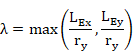
![]()
![]()
The buckling parameter u and the torsional index x are calculated as follows:
· For I and H sections

![]()
![]()
· For Channel sections


![]()
Where:
|
J |
Torsion constant (mechanical property of the section). |
|
|
Thickness of the compression flange. |
|
|
Thickness of the tension flange. |
|
|
Plastic modulus about the major axis. |
|
|
Moment of inertia about the major axis (mechanical property of the section). |
|
|
Moment of inertia about the minor axis (mechanical property of the section). |
|
A |
Cross sectional area (mechanical property of the section). |
|
H |
Warping constant (mechanical property of the section). |
The slenderness factor (v parameter) is given by:

![]()
Where:
|
|
Moment of area of the compression flange about the minor axis of the section. |
|
|
Moment of area of the tension flange about the minor axis of the section. |
|
|
Monosymmetry index, for I and T sections with lipped flanges. |
The monosymmetry index ![]() is calculated as
follows:
is calculated as
follows:
![]() for
for ![]()
![]() for
for ![]()
Where:
|
D |
Overall depth of the section (mechanical property of the section). |
|
DL |
Depth of the lip. By default DL=0. |
B. Equivalent slenderness determination for Box Sections including RHS (Appendix B.2.6)
The equivalent slenderness, ![]() , for box sections
is taken directly from the expression below:
, for box sections
is taken directly from the expression below:
![]()

![]()
C. Equivalent slenderness determination for T sections (Appendix B.2.8)
The equivalent slenderness, ![]() , for T sections is obtained
from the following:
, for T sections is obtained
from the following:
a) If ![]() =
= ![]() : Lateral torsional
buckling does not occur and
: Lateral torsional
buckling does not occur and ![]()
b) If ![]() : Lateral
torsional buckling occurs about the x-x axis and
: Lateral
torsional buckling occurs about the x-x axis and ![]() is given by:
is given by:
![]()
c) If: ![]()
![]()
![]() Lateral torsional
buckling occurs about the x-x axis and
Lateral torsional
buckling occurs about the x-x axis and ![]() is given by:
is given by:
![]()


![]()
![]()
![]()
D. Equivalent slenderness determination for Equal Angle sections (Appendix B.2.9.1)
The equivalent slenderness, ![]() , for equal angle
sections is obtained from the following:
, for equal angle
sections is obtained from the following:
![]()

![]()
![]()
E. Equivalent slenderness determination for Unequal Angle sections (Appendix B.2.9.2)
The equivalent slenderness, ![]() , for unequal angle
sections is obtained from the following:
, for unequal angle
sections is obtained from the following:
![]()


The monosymmetry index ![]() for an unequal
angle is taken as positive when the short leg is in compression and negative
when the long leg is in compression.
for an unequal
angle is taken as positive when the short leg is in compression and negative
when the long leg is in compression.
![]() is the coordinate
of the shear center along the v-v axis.
is the coordinate
of the shear center along the v-v axis.
|
Result |
Concepts |
Articles |
Description |
|
MB |
|
4.3.6 |
Buckling resistance moment |
|
UMLT |
|
4.3.6 |
Equivalent uniform moment |
|
M |
m |
|
Equivalent uniform moment factor |
|
LAMBDA |
Lambda |
B.2 |
Slenderness |
|
LAMBDALT |
LambdaLT |
B.2 |
Equivalent slenderness |
|
LAMBDALO |
LambdaLO |
B.2 |
Limiting equivalent slenderness |
|
CRT_TOT |
|
4.3.6 |
Global criterion |
|
CLASS |
|
3.5.2 |
Section class |
|
WEBCLASS |
|
3.5.2 |
Web class |
1. Forces and moments selection.
The forces and moments considered for this checking type are:
|
F = FX |
Design value of the axial force (positive if tensile, element not processed if compressive). |
2. Class determination.
3.
Criteria calculation.
For members under axial tension, the general criterion Crt_TOT is checked at
each section. This criterion coincides with the axial criterion Crt_N:
![]() à
à ![]()
Where Pt is the tension capacity: ![]()
4. Output results are written in the CivilFEM results file (.CRCF). Checking results: criteria and variables are described in the following table:
|
Result |
Concepts |
Articles |
Description |
|
F |
F |
4.6.1 |
Tension Force |
|
PT |
|
4.6.1 |
Tension capacity |
|
CRT_TOT |
|
4.6.1 |
Global criterion |
1.
Forces and moments selection.
The forces and moments considered for this checking type are:
|
F = FX |
Design value of the axial force (negative if it is compressive). If it is tensile, the element is not processed. |
2. Class determination.
3.
Criteria calculation.
For members under axial compression, the general criterion Crt_TOT is checked
at each section. This criterion coincides with the axial compression criterion
Crt_CB:
![]() à
à ![]()
Where:
|
F |
Axial compression force. |
|
|
Compressive strength for buckling. |
The compressive strength is determined according to the article 4.7.4 of BS 5950:2000:
· For class 1, 2 or 3 sections:
![]()
· For class 4 sections:
![]()
Where:
|
|
Gross sectional area. |
|
|
Effective cross sectional area. |
|
|
Compressive strength. |
|
|
Compressive strength for a reduced slenderness of |
The compressive strength may be obtained from (See Appendix C):

![]()
Where:
|
|
Design strength (reduced by 20N/mm2 for welded I, H or box sections). |
|
|
Euler strength: |
|
E |
Material elasticity modulus. |
|
|
Slenderness: |
|
|
Radius of gyration about the relevant axis. |
|
|
Effective buckling length: |
|
L |
Actual length of the member. |
|
|
Correction factors of buckling lengths for planes XZ and YZ. |
The Perry coefficient η for flexural buckling under load should be taken as follows (Appendix C.2):
![]()
Where ![]() is the limiting
slenderness:
is the limiting
slenderness:

The constant a (Robertson constant) is determined by the program from the type of section and buckling axis, according to the table 23 of the BS 5950:2000. Therefore, if the user introduces a value for this constant in member properties, the program will give precedence to the user’s value.
|
a= |
2.0 for curve (a) |
|
a= |
3.5 for curve (b) |
|
a= |
5.5 for curve (c) |
|
a= |
8.0 for curve (d) |
To distinguish between I and H shapes the program follows the criteria below:
I
shapes if ![]()
H
shapes if ![]()
4. Output results are written in the CivilFEM results file (.CRCF). Checking results: criteria and variables are described in the following table.
|
Result |
Concepts |
Articles |
Description |
|
F |
F |
4.7 |
Compression Force |
|
PC |
|
4.7.4 |
Compression capacity |
|
RHOC |
|
4.7.5 |
Compression Resistance |
|
LAMBDA |
Lambda |
4.7.2 |
Slenderness |
|
LAMBDA0 |
Lambda0 |
C.2 |
Limiting slenderness |
|
PERRYFCT |
NU |
C.2 |
Perry factor |
|
ROBERSTS |
a |
C.2 |
Robertson constant |
|
CRT_TOT |
|
4.7 |
Global criterion |
|
WEBCLASS |
|
3.5.2 |
Web class |
|
CLASS |
|
3.5.2 |
Section class |
1.
Forces and moments selection.
The forces and moments considered for this checking type are:
|
F = FX |
Design value of the axial force. |
|
|
Design value of the bending moment along the primary bending axis. |
|
|
Design value of the bending moment about the secondary bending axis. |
2. Class determination.
3. Criteria calculation.
For members subjected to an axial tension force and bending moments, each section should be checked according the same conditions for members subjected to a shear force and bending moments (see section 9.8.3 of this manual).
Therefore, for this type of checking, the following conditions are checked:
3.1 Shear checking in both directions
![]()
![]()
Where ![]() and
and ![]() are the shear
forces about X and Y axis, and
are the shear
forces about X and Y axis, and ![]() and
and ![]() the shear capacity
about X and Y axis.
the shear capacity
about X and Y axis.
3.2 Shear buckling resistance of shear webs
![]()
![]()
Where Vwx and Vwy are the shear buckling resistance about X and Y axis, respectively.
![]()
![]()
3.3 Checking of axial force and bending moments
Each section is checked according to the following condition:

Equivalent to:
Crt_CMP = Crt_AXL + Crt_Mx + Crt_My £ 1
![]()
![]()

Where:
|
F |
Axial force. |
|
|
Bending moment about major axis. |
|
|
Bending moment about minor axis. |
|
|
Effective net area of the section. |
|
|
Design strength of the material. |
|
|
Moment capacity about major axis. |
|
|
Moment capacity about minor axis. |
![]() and
and ![]() are calculated
according to the Article 4.2.5 of BS 5950:2000.
are calculated
according to the Article 4.2.5 of BS 5950:2000.
For this checking type (moments on both directions), the shear area,
the plastic modulus and the ![]() parameter are
calculated with respect to both directions (X and Y axis).
parameter are
calculated with respect to both directions (X and Y axis).
3.3 Checking of global criterion
CRT_TOT = Max (Crt_CMP, Crt_VX, Crt_VPX, Crt_VY, Crt_VPY)
4. Output results are written in the CivilFEM results file (.CRCF). Checking results: criteria and variables are described in the following table.
|
Result |
Concepts |
Articles |
Description |
|
F |
F |
|
Axial tension force |
|
MX |
|
4.2.5 |
Bending moment about major axis |
|
MY |
|
4.2.5 |
Bending moment about minor axis |
|
FVX |
|
|
Shear force about major axis |
|
FVY |
|
|
Shear force about minor axis |
|
PVX |
|
4.2.3 |
Shear capacity about major axis |
|
PVY |
|
4.2.3 |
Shear capacity about minor axis |
|
PT |
|
4.6.1 |
Axial Tension Capacity |
|
MCX |
|
4.2.5 |
Moment capacity about major axis |
|
MCY |
|
4.2.5 |
Moment capacity about minor axis |
|
CRT_AXL |
|
4.6.1 |
Axial Criterion |
|
CRT_VX |
|
4.2.3 |
Shear Criterion about major axis |
|
CRT_VY |
|
4.2.3 |
Shear Criterion about minor axis |
|
CRT_MX |
|
4.2.5 |
Bending Criterion about major axis |
|
CRT_MY |
|
4.2.5 |
Bending Criterion about minor axis |
|
CRT_PVX |
|
4.4.5 |
Buckling web Criterion about major axis |
|
CRT_PVY |
|
4.4.5 |
Buckling web Criterion about minor axis |
|
CRT_CMP |
Crt_AXL + Crt_MX + Crt_MY |
4.8.2 |
Axial + moments Criterion |
|
SVX |
|
4.2.6 |
Sv parameter for major axis |
|
SVY |
|
4.2.6 |
Sv parameter for minor axis |
|
CRT_TOT |
|
4.8.2 |
Global criterion |
|
AVX |
|
4.2.3 |
Shear Area for major axis |
|
AVY |
|
4.2.3 |
Shear Area for minor axis |
|
VWX |
|
4.4.5 |
Shear buckling resistant for major axis |
|
VWY |
|
4.4.5 |
Shear buckling resistant for minor axis |
|
MDFX |
|
4.2.6 |
Resistant modulus for major axis |
|
MDFY |
|
4.2.6 |
Resistant modulus for minor axis |
|
ZX |
|
4.2.6 |
Elastic Modulus about major axis |
|
SX |
|
4.2.6 |
Plastic Modulus about major axis |
|
ZY |
|
4.2.6 |
Elastic Modulus about minor axis |
|
SY |
|
4.2.6 |
Plastic Modulus about minor axis |
|
CLASS |
|
3.5.2 |
Sections class |
|
WEBCLASS |
|
3.5.2 |
Web’s class |
1.
Forces and moments selection.
The forces and moments considered for this checking type are:
|
F = FX |
Design value of the axial force. |
|
|
Design value of the shear force perpendicular to the primary bending axis. |
|
|
Design value of the shear force perpendicular to the secondary bending axis. |
|
|
Design value of the bending moment along the primary bending axis. |
|
|
Design value of the bending moment about the secondary bending axis. |
2. Class determination.
3. Criteria calculation.
Compression members are checked for local capacity at the points of
greatest bending and axial load. This capacity may be limited by either
yielding or local buckling, depending on the section properties. The member is
then checked for global buckling.
Therefore, for this type of checking, the following conditions are checked:
3.1 Local Capacity Check
3.1.1 Axial Criterion
![]()
Where:
|
F |
Axial load |
|
|
Compression capacity: For
class 1, 2 or 3 sections: For
class 4 sections: |
3.1.2 Local criteria as for Tension Members with Moments
Bending criterion (major axis)= Crt_MX_L
Bending criterion (minor axis)= Crt_MY_L
Shear criterion about major axis= Crt_VX
Shear criterion about minor axis = Crt_VY
Buckling web Criterion about major axis = Crt_PVX
Buckling web Criterion about minor axis = Crt_PVY
3.1.3 Component Local Criterion
![]()
3.2 Overall Buckling Check
3.2.1 Axial Criterion (Buckling)
![]()

Where:
|
F |
Design value of the axial compressive force. |
|
|
Compression resistance. |
|
|
Compresion resistance, considering buckling about the minor axis only: For
class 1, 2 or 3 sections: For
class 4 sections: |
|
|
Gross sectional area. |
|
|
Compressive strength obtained according article 4.7.5 of the code. |
3.2.2 Bending Moment Criterion (primary axis)

![]()
Where:
|
|
Equivalent uniform moment factor. By default |
|
|
Equivalent uniform moment factor for lateral torsional buckling.
By default |
|
|
Bending moment about major axis. |
|
|
Buckling resistance moment according the article 4.3 of the code. |
|
|
Maximum major axis moment . |
3.2.3 Bending Moment Criterion (secondary axis)

Where:
|
|
Equivalent uniform moment factor. By default |
|
|
Bending moment about minor axis. |
|
|
Elastic modulus about the minor axis (for slender class 4 sections
|
3.2.4 Component Global Criterion
![]()

![]()

![]()
![]()
3.3 Total Criterion
Crt_TOT=Max(Crt_CM_L,Crt_CM_O,Crt_VX, Crt_VPX, Crt_VY,Crt_VPY)
4. Output results are written in the CivilFEM results file (.CRCF). Checking results: criteria and variables are described in the following table.
|
TABLE |
Concepts |
Articles |
Description |
|
F |
F |
|
Design value of the axial compressive force |
|
PC |
|
4.7.4 |
Compression resistance |
|
FVX |
|
|
Shear force about major axis |
|
MX |
|
|
Bending moment about major axis |
|
ZX |
|
4.2.5 |
Elastic Modulus about major axis |
|
SX |
|
4.2.5 |
Plastic Modulus about major axis |
|
SVX |
|
4.2.5 |
Sv parameter for major axis |
|
AVX |
|
4.2.3 |
Shear Area for major axis |
|
VWX |
|
4.4.5 |
Shear buckling resistant for major axis |
|
MDFX |
|
4.2.5 |
Resistant modulus for major axis |
|
PVX |
|
4.2.3 |
Shear capacity about major axis |
|
MCX |
|
4.2.5 |
Moment capacity about major axis |
|
FVY |
|
|
Shear force about minor axis |
|
MY |
|
|
Bending moment about minor axis |
|
ZY |
|
4.2.5 |
Elastic Modulus about minor axis |
|
SY |
|
4.2.5 |
Plastic Modulus about minor axis |
|
SVY |
|
4.2.5 |
Sv parameter for minor axis |
|
AVY |
|
4.2.3 |
Shear Area for minor axis |
|
VWY |
|
4.4.5 |
Shear buckling resistant for minor axis |
|
MDFY |
|
4.2.5 |
Resistant modulus for minor axis |
|
PVY |
|
4.2.3 |
Shear capacity about minor axis |
|
MCY |
|
4.2.5 |
Moment capacity about minor axis |
|
M |
M |
4.8.3.3 |
Equivalent uniform moment factor |
|
LAMBDA |
Lambda |
4.3.7.5 |
Slenderness |
|
LAMBDA0 |
Lambda0 |
C.2 |
Limiting slenderness |
|
LAMBDALT |
LambdaLT |
4.3.7.5 |
Equivalent slenderness |
|
LAMBDAL0 |
LambdaL0 |
B.2.4 |
Limiting equivalent slenderness |
|
PERRYFCT |
NU |
C.2 |
Perry Factor |
|
MB |
|
4.3.7 |
Buckling resistance moment capacity |
|
CRT_TOT |
Max(Crt_CM_L, Crt_CM_O, Crt_VX, Crt_VY, ...) |
4.8.3 |
Total Criterion |
|
CRT_CM_L |
Crt_AX_L + Crt_MX_L + Crt_MY_L |
4.8.3 |
Local Axial + moments Criterion |
|
CRT_CM_O |
Crt_AX_O + Crt_MX_O + Crt_MY_O |
4.8.3 |
Global Axial + moments Criterion |
|
CRT_AX_L |
|
4.8.3 |
Local axial criterion |
|
CRT_MX_L |
|
4.2.5 |
Local bending moment criterion about X axis |
|
CRT_MY_L |
|
4.2.5 |
Local bending moment criterion about Y axis |
|
CRT_AX_O |
|
4.8.3 |
Global axial criterion |
|
CRT_MX_O |
|
4.8.3 |
Global bending moment criterion about X axis |
|
CRT_MY_O |
|
4.8.3 |
Global bending moment criterion about Y axis |
|
CRT_VX |
|
4.2.3 |
Shear criterion about X axis |
|
CRT_PVX |
|
4.4.5 |
Buckling web Criterion about major axis |
|
CRT_VY |
|
4.2.3 |
Shear criterion about Y axis |
|
CRT_PVY |
|
4.4.5 |
Buckling web Criterion about minor axis |
|
CLASS |
Class |
3.5.2 |
Section Class |
|
WEBCLASS |
Webclass |
3.5.2 |
Web’s Class |
Steel structures checking according to ASME BPVC III Subsection NF in CivilFEM includes the checking of structures composed of welded or rolled shapes under axial forces, shear forces and bending moments in 3D.
The calculations performed by CivilFEM correspond to the provisions of this code according to the following sections:
|
1 |
Allowable Stresses |
|
2 |
Stability and Slenderness and Width-Thickness Ratios |
With CivilFEM it is possible to accomplish the following checking and analysis types:
![]() Checking
of sections
(ASME NF-3322.1) subjected
to:
Checking
of sections
(ASME NF-3322.1) subjected
to:
|
Stress in Tension |
|
Stress in Shear |
|
Stress in Compression |
|
Stress in Bending |
|
Axial Compression and Bending |
|
Axial Tension and Bending |
![]() Stability
check (ASME
NF-3322.2):
Stability
check (ASME
NF-3322.2):
|
Maximum Slenderness Ratios |
|
Width Ratios |
The following material properties are used for checking according to ASME BPVC III Subsection NF:
|
Description |
Property |
|
Steel yield strength |
|
|
Ultimate strength |
|
|
Modulus of Elasticity |
E |
*th = plate thickness
Furthermore, although austenitic stainless steel is an intrinsic material property, it can be modified by changing the material property.
The section data of the element must be included in the CivilFEM database. All geometrical and mechanical properties are automatically obtained when defining the cross section or capturing the solid section. The section data required for checking according to this code are listed below:
|
Data |
Description |
|
A |
Area of the cross-section |
|
|
Moment of inertia about Y axis |
|
|
Moment of inertia about Z axis |
|
|
Product of inertia about YZ |
|
Y |
Coordinate Y of the considered fiber |
|
Z |
Coordinate Z of the considered fiber |
|
|
Radius of gyration about Y axis |
|
|
Radius of gyration about Z axis |
|
|
Shear area in Y |
|
|
Shear area in Z |
From the net section, only the area is considered. This area is calculated by subtracting the holes for screws, rivets and other holes from the gross sectional area. The user should be aware that the code indicates the diameter used to calculate the area of holes is greater than the real diameter. The area of holes is introduced within the structural steel code properties.
In order to determine
the effective net area ![]() of axially loaded
tension members, the reduction coefficient Ct must be set (parameter). By default, Ct=0.75.
of axially loaded
tension members, the reduction coefficient Ct must be set (parameter). By default, Ct=0.75.
For ASME BPVC III Subsection NF, the data set checked at member level is shown in the following table.
|
Description |
Data |
Chapter |
|
1.- Unbraced length of the member 2.- Buckling length factor in Y axis 3.- Buckling length factor in Z axis 4.- Bending coefficient dependent upon moment gradient in Y axis 5.- Bending coefficient dependent upon moment gradient in Z axis 6.- Coefficient applied to bending term in interaction equation and dependent upon column curvature caused by applied moments in Z axis 7.- Coefficient applied to bending term in interaction equation and dependent upon column curvature caused by applied moments in Y axis 8.- Pin-connected members: 0: No (default) 1: Yes 9.- Member type: 0: Beam (default) 1: Column 9.- Laterally braced in the region of compression: 0: No (default) 1: Yes |
L KY KZ CBY
CBZ
CMY
CMZ
PIN
COLUMN
BRACED |
3322 3322 3322 3322
3322
3322
3322
3322
3322
3322
|
Necessary steps to conduct the different checks in CivilFEM are as follows:
a) Obtain the cross-sectional data corresponding to the element.
b) Specific section checking according to the type of external load.
c) Results. In CivilFEM, checking results for each element end are stored in the results file .CRCF
The required data for the different types of checking can be found in tables within the corresponding sections in this manual.
In CivilFEM, elements subjected to tension are checked according to ASME BPVC III Subsection NF code for each end of the selected elements and solid sections of the model with a structural steel cross section. The check for tension adheres to the following steps:
The allowable stress in tension shall be as given in the equations below:
Except for pin-connected and threaded members, Ft shall be:
![]()
(*)
![]() on the effective net area
on the effective net area
For pin-connected members, using the net area:
![]()
The obtained equivalent stress ![]() is divided by the
steel design strength
is divided by the
steel design strength ![]() in order to obtain
a value that is stored as the CRT_STR parameter in the corresponding
alternative. This value must be between 0.0 and 1.0 for the element to be valid
according to the ASME BPVC III Subsection NF code; consequently, the equivalent
stress must be less than the steel design strength.
in order to obtain
a value that is stored as the CRT_STR parameter in the corresponding
alternative. This value must be between 0.0 and 1.0 for the element to be valid
according to the ASME BPVC III Subsection NF code; consequently, the equivalent
stress must be less than the steel design strength.
![]()
The maximum slenderness ratio l/r for tension members is obtained and stored as SLD_RT. This slenderness ratio is divided by 240 (SLD_RT shall not exceed 240) and stored as the CRT_SLD. Therefore, this value must be between 0.0 and 1.0 for the element to be valid according this code.
![]()
![]()
The Total Criterion is obtained from the maximum value between the stress criterion and the slender criterion; this criterion is stored as the CRT_TOT parameter in the corresponding alternative in CivilFEM’s results file for each element end. This value must be between 0.0 and 1.0 for the element to be valid according the ASME BPVC III Subsection NF code.
CRT_TOT=MAX(CRT_STR,CRT_SLD)
In CivilFEM the elements subjected to a shear force are checked according to ASME BPVC III Subsection NF code is done for each element end of those selected elements or solid sections of the model with a structural steel cross section.
The allowable stress for shear resistance of the effective section is as follows:
![]()
The equivalent stress obtained ![]() is divided by the
steel design strength
is divided by the
steel design strength ![]() in order to obtain
a value that is stored as the CRT_TOT parameter in the active alternative in
the CivilFEM’s results file for each element end. This value must be between
0.0 and 1.0 so that the element will be valid according to the ASME BPVC III
Subsection NF code; consequently, the equivalent stress must be less than the
steel design strength.
in order to obtain
a value that is stored as the CRT_TOT parameter in the active alternative in
the CivilFEM’s results file for each element end. This value must be between
0.0 and 1.0 so that the element will be valid according to the ASME BPVC III
Subsection NF code; consequently, the equivalent stress must be less than the
steel design strength.
![]()
This equivalent stress fv is the maximum value obtained in both directions:
![]()
In CivilFEM, elements subjected to compression are checked of according to ASME BPVC III Subsection NF for each element end of the selected elements or solid sections of the model with a structural steel cross section.
The allowable stress in compression shall be determined as described below:
1- Gross sections of columns, except those fabricated from austenitic stainless steel:

![]()
where

2- Gross sections of columns fabricated from austenitic stainless steel:
![]() if kI/r
if kI/r ![]()
![]() if kI/r
if kI/r ![]() 120
120
3- Member elements other than columns:
![]()
The maximum slenderness ratio l/r for tension members is obtained and stored as SLD_RT. This slenderness ratio is divided by 200 (SLD_RT shall not exceed 200) and stored as the parameter CRT_SLD. Consequently, this value must be between 0.0 and 1.0 for that the element to be valid according this code.
![]()
![]()
The ASME BPVC III Subsection NF code decreases the efficiency of a section through reduction factors when axially loaded members contain elements subjected to compression and have a width-thickness ratio above the limit below:
Unstiffened compression elements have one free edge parallel to the direction of the compressive stress. Stress on these elements shall be decreased by the reduction factor Qs when the width-thickness ratio exceeds the limits below. The flange width will be the distance from the free edge to the web.
1- For Single Angles,
when ![]()
Qs = 1.0
when ![]()
![]()
![]()
when b/t ![]() 155/
155/![]()
![]()
2- For Stems of Tees,
when ![]()
![]()
when ![]()
![]()
when ![]()
![]()
3- For other Compression Members,
when ![]()
![]()
when ![]()
![]()
when ![]()
![]()
where Sy is the yield strength, in ksi.
Furthermore, proportions of unstiffened elements of channels and tees that exceed the limits above are checked for the following limits:
|
Shape |
Ratio of Flange Width to Profile Depth |
Ratio of Flange Thickness to Web or Stem Thickness |
|
Built-up Channels |
|
|
|
Rolled Channels |
|
|
|
Built-up Tees |
|
|
|
Rolled Tees |
|
|
Table NF-3322.2(e)(2)-1
This proportion checking result is defined in the CivilFEM results file (.CRCF) as CTR_W with a value of 0.0 if the proportional limits are fulfilled and 2100 if they are not.
Stiffened compression elements have lateral support along both edges which are parallel to the direction of the compressive stress. If the width-thickness ratio of these elements exceeds the limit below, a reduced effective width be shall be used:
1- For the flanges of square and rectangular sections of uniform thickness:
when ![]()
![]()
2- For other uniform compressed elements:
when ![]()
![]()
Where f is the axial compressive stress on the member based on the effective area, in ksi.
If unstiffened elements are included in
the total cross section, f must be such that the maximum compressive stress in
the unstiffened elements does not exceed ![]() . Therefore, the
calculation of the effective width of stiffened elements adheres to the following
iterative process:
. Therefore, the
calculation of the effective width of stiffened elements adheres to the following
iterative process:
a) The axial compressive stress f is obtained.
b) An initial value of the effective width ![]() is calculated.
is calculated.
c) A new axial compressive stress f’ of the effective area is obtained
d) If f’ exceeds ![]() , a new axial
compressive stress f’’ is obtained by increasing the last axial compressive
stress f’.
, a new axial
compressive stress f’’ is obtained by increasing the last axial compressive
stress f’.
This process is repeated until the axial
compressive stress does not exceed ![]() or until the effective area is equal to the total area.
or until the effective area is equal to the total area.
Using the effective
width ![]() , the form factor
, the form factor ![]() is then calculated by the ratio of the effective area to the total area.
is then calculated by the ratio of the effective area to the total area.
![]()
![]()
The allowable stress for axially loaded compression members shall not exceed:

After verifing the equation above, the
equivalent stress obtained ![]() is divided by the
steel design strength
is divided by the
steel design strength ![]() to obtain a value
stored as the CRT_STR parameter in the active alternative in CivilFEM’s results
file for each element end. This value must be between 0.0 and 1.0 so that the
element will be valid according to ASME BPVC III Subsection NF; therefore, the
equivalent stress must be lower than the steel design strength.
to obtain a value
stored as the CRT_STR parameter in the active alternative in CivilFEM’s results
file for each element end. This value must be between 0.0 and 1.0 so that the
element will be valid according to ASME BPVC III Subsection NF; therefore, the
equivalent stress must be lower than the steel design strength.
![]()
The Total Criterion is obtained from the maximum value between the stress criterion and the slender criterion and is stored as the CRT_TOT parameter in the active alternative in the CivilFEM’s results file for each element end. This value must be between 0.0 and 1.0 for the element to be valid according to the ASME BPVC III Subsection NF.
![]()
In CivilFEM, elements subjected bending are checked according to ASME BPVC III Subsection NF for each element end of the selected elements or solid sections of the model with a structural steel cross section.
First, the section is classified as a compact section, member with a high flange width-thickness ratio or miscellaneous member:
(a) Compact sections: For a section to qualify as compact, its flanges must be continuously connected to the web or webs and the width-thickness ratios of its compression elements must not exceed the limiting ratios below:
1- The width-thickness ratio of the compression flanges shall not exceed:
a.
for unstiffened elements ![]()
b. for stiffened elements ![]()
2- Depth-thickness ratio of webs
![]() if
if ![]()
![]()
3-
Moreover, the compression flanges shall be
braced laterally at intervals not exceeding ![]() nor
nor ![]() . This property is
set by the user as a structural steel code property. If the cross section has
no compression flanges, the member will be taken into account as braced
laterally.
. This property is
set by the user as a structural steel code property. If the cross section has
no compression flanges, the member will be taken into account as braced
laterally.
(b) Members with a high flange width-thickness ratio: members shall satisfy the requirements above, except unstiffened flanges shall satisfy:
![]()
(c) Miscellaneous members: limit ratios above do not apply to these members.
Next, the allowable bending stress is determined by the equations below:
1- I Sections:
a. Compact sections bent about their minor axis of inertia shall not exceed a bending stress of:
![]()
b. Members with a high flange width-thickness ratio bent about their minor axis of inertia shall not exceed a bending stress of:
![]()
c. Compact sections bent about their major axis of inertia shall not exceed:
![]()
d. Members with a high flange width-thickness ratio bent about their major axis of inertia shall not exceed a bending stress of:
![]()
e. Miscellaneous member sections bent about their major axis of inertia shall not exceed the larger value below:
![]()
when ![]()
![]()
when ![]()
where ![]() is the radius of the
section, comprising of the area of the compression flange plus one-third of the
area of the compression web.
is the radius of the
section, comprising of the area of the compression flange plus one-third of the
area of the compression web.
When the area of the compression flange is greater than or equal to the area of the tension flange:
![]()
f. Members not included above which are braced laterally in the region of the compressive stress shall not exceed a bending stress of:
![]()
If these members are not braced laterally in the region of the compressive stress, the section will be not checked.
2- Tubular Square Box Sections:
a. Compact sections bent about their minor axis of inertia, but not necessarily braced laterally, shall not exceed a bending stress of:
![]()
b. Members not included shall not exceed a bending stress of:
![]()
However, this section strength can be decreased through reduction factors.
3- Pipe Sections:
a.
If the diameter-thickness ratio of hollow,
circular sections does not exceed ![]() , the bending stress
shall not exceed:
, the bending stress
shall not exceed:
![]()
If the diameter-thickness ratio is greater than the value above, the section will be not checked.
4- U channel Sections:
a. If the section is bent about its major axis of inertia, the bending stress shall not exceed the larger value below:
![]()
when ![]()
![]()
when ![]()
where ![]() is the radius of
the section, comprising of the area of the compression flange plus one-third of
the area of the compression web.
is the radius of
the section, comprising of the area of the compression flange plus one-third of
the area of the compression web.
When the area of the compression flange is greater than or equal to the area of the tension flange,
![]()
b. Members not included above which are braced laterally in the region of the compressive stress shall not exceed a bending stress of:
![]()
If these members are not braced laterally in the region of the compressive stress, the section will be not checked.
5- Tees Sections:
a. Compact sections loaded in the direction of the web which coincides with the minor axis of inertia, shall not exceed a bending stress of:
![]()
b. Members with a high flange width-thickness ratio which are loaded in the direction of the web coinciding with the minor axis of inertia shall not exceed a bending stress of:
![]()
c. Miscellaneous member sections loaded in the direction of the web coinciding with the minor axis of inertia, shall not exceed the larger bending stress below:
![]()
when ![]()
![]()
When ![]()
where ![]() is the radius of a
section comprising the area of the compression flange plus one-third of the
area the of compression web
is the radius of a
section comprising the area of the compression flange plus one-third of the
area the of compression web
When the compression flange area is greater than or equal to the tension flange area:
![]()
d. Members not included above which are braced laterally in the region of the compressive stress shall not exceed a bending stress of:
![]()
If these members are not braced laterally in the region of the compressive stress, the section will be not checked.
6- All other sections:
a. Members braced laterally in the region of the compressive stress shall not exceed a bending stress of:
![]()
If these members are not braced laterally in the region of compressive stress, the section will be not checked.
ASME BPVC III Subsection NF Code decreases the efficiency of a section through reduction factors for flexural members containing elements subject to compression with a width-thickness ratio in excess of the limits below:
Unstiffened compression elements have one free edge parallel to the direction of the compressive stress. When the width-thickness ratio exceeds the limits below, the stress calculation will include a reduction of factor Qs. The width of flanges is taken from distance from the free edge to the weld.
1- For Single Angles:
when ![]()
![]()
when ![]()
![]()
when ![]()
![]()
2- For Stems of Tees:
when ![]()
![]()
when ![]()
![]()
when ![]()
![]()
3- For Other Compression Members:
when ![]()
![]()
when ![]()
![]()
when ![]()
![]()
where Sy is the yield strength, in ksi.
Furthermore, unstiffened elements of channels and tees with proportions that exceed the limits above are checked for the following limits:
|
Shape |
Ratio of Flange Width to Profile Depth |
Ratio of Flange Thickness to Web or Stem Thickness |
|
Built-up channels |
|
|
|
Rolled channels |
|
|
|
Built-up tees |
|
|
|
Rolled tees |
|
|
Table NF-3322.2(e)(2)-1
This proportion checking result is written in the CivilFEM results file (.CRCF) as CTR_W with a value of 0.0 if the proportion limits are satisfied and 2100 if they are not.
Stiffened compression elements have lateral
support along both edges which are parallel to the direction of the compressive
stress. When the width-thickness ratio of these elements exceeds the applicable
limit below, a reduced effective width ![]() shall be used:
shall be used:
1- For the flanges of square and rectangular sections of uniform thickness,
when ![]()
![]()
2- For other uniform compressed elements,
When ![]()
![]()
Where f is the compressive stress on member based on the effective area, in ksi.
If unstiffened elements are included in
the total cross section, f must have a value such that the maximum compressive
stress in the unstiffened elements does not exceed ![]() . Therefore, the
calculation of the effective width of stiffened elements adheres to the
following iterative process:
. Therefore, the
calculation of the effective width of stiffened elements adheres to the
following iterative process:
a) The maximum compressive stress f of the element is obtained
b) An initial value of the effective width ![]() is calculated in all
the compressive elements.
is calculated in all
the compressive elements.
c) A new axial compressive stress f’ is obtained of the effective area.
d) If f’ exceeds ![]() , a new effective
width
, a new effective
width ![]() ’ is obtained by
increasing the previous effective width
’ is obtained by
increasing the previous effective width ![]() .
.
This iteration is repeated until the axial
compressive stress is less than ![]() or the effective
area is equal to the total area.
or the effective
area is equal to the total area.
Using the effective
width ![]() , the form factor
, the form factor ![]() is then calculated by the ratio of the effective area to the total area.
is then calculated by the ratio of the effective area to the total area.
![]()
![]()
When reduction factors are required, the
maximum allowable bending stress shall not exceed 0.6 ![]() or the
or the ![]() value as provided
above.
value as provided
above.
The computed bending stress ![]() , obtained from the effective area, is divided by the steel design
strength
, obtained from the effective area, is divided by the steel design
strength ![]() in order to obtain
a value that is stored as the CRT_TOT parameter in the active alternative in
CivilFEM’s results file for each element end. This value must be between 0.0
and 1.0 so that the element will be valid according to ASME BPVC III Subsection
NF; therefore, the equivalent stress must be less than the steel design
strength.
in order to obtain
a value that is stored as the CRT_TOT parameter in the active alternative in
CivilFEM’s results file for each element end. This value must be between 0.0
and 1.0 so that the element will be valid according to ASME BPVC III Subsection
NF; therefore, the equivalent stress must be less than the steel design
strength.
![]()
In CivilFEM the checking of elements under bending and axial compression forces according to ASME BPVC III Subsection NF code are done for each element end of those selected elements or solid sections of the model whose cross section type is structural steel.
For members subjected to both axial compression and bending, stresses shall satisfy the requirements of the following equations:
![]()
![]()
When evaluating both primary and secondary stresses:
![]()
When evaluating primary stresses:
![]()
The Total Criterion will be the maximum value of the equations below and will be stored as the CRT_TOT parameter in the active alternative in CivilFEM’s results file for each element end. This value must be between 0.0 and 1.0 for the element to be valid according to ASME BPVC III Subsection NF; therefore, the equivalent stress must be less than the steel design strength.
In CivilFEM, elements subjected bending and axial tension forces are checked according to ASME BPVC III Subsection NF for each element end of the selected elements or solid sections of the model with a structural steel cross section.
Members subject to both axial tension and bending stresses shall satisfy the requirements of the following equation:
![]()
Where fb is the computed bending tensile stress. However, the computed bending compressive stress, taken alone, shall not exceed the allowable compressive stress Fa.
Therefore, the total criterion will be:
![]()
Where fbc is the computed bending compressive stress.
The total criterion is stored as the CRT_TOT parameter in the active alternative in CivilFEM’s results file for each element end. This value shall be between 0.0 and 1.0 for the element to be valid according to ASME BPVC III Subsection NF; consequently, the equivalent stress must be less than the steel design strength.
Steel structures checking according to the Chinese Steel Design Code GB50017 in CivilFEM includes the checking of structures composed of welded or rolled shapes subjected to axial forces, shear forces and bending moments in 3D.
The calculations made by CivilFEM correspond to the provisions of GB50017 from the following sections:
|
Section 4 |
Bending element calculations |
|
Section 5 |
Axially loaded structures and calculation of compression and bending |
For checks within CivilFEM according to GB50017, it is possible to accomplish the following checking and analysis types:
Checking of sections subjected to:
|
- Bending force |
GB50017 Art. 4.1.1 |
|
- Shear force |
GB50017 Art. 4.1.2 |
|
- Bending and shear force |
GB50017 Art. 4.1.4 |
|
- Axial force |
GB50017 Art. 5.1.1 |
|
- Bending and axial force |
GB50017 Art. 5.2.1 |
|
- Compression buckling |
GB50017 Art. 5.1.2 |
In GB50017 checking, the following material properties are used:
|
Description |
Property |
|
Steel yield strength |
|
|
Ultimate strength |
|
|
Shear strength |
|
|
Elasticity modulus |
E |
*th = plate thickness
The section data of the element must be included in the CivilFEM database. All geometrical and mechanical properties are automatically obtained defining the cross section or capturing the solid section. Below, the section data necessary for checking according to GB50017 are listed:
|
Data |
Description |
|
A |
Area of the cross-section |
|
|
Moment of inertia about Y axis |
|
|
Moment of inertia about Z axis |
|
|
Product of inertia about YZ |
|
Y |
Coordinate Y of the considered fiber |
|
Z |
Coordinate Z of the considered fiber |
|
|
Radius of gyration about Y axis |
|
|
Radius of gyration about Z axis |
|
|
Shear area in Y |
|
|
Shear area in Z |
|
|
Torsional modulus |
From net section, only the area is considered. This area is calculated by subtracting the holes for screws, rivets and other holes from the gross section area. The user should be aware that LRFD indicates the diameter from which to calculate the area of holes is greater than the real diameter. The area of holes is introduced within the structural steel code properties.
For LRFD, the checked data set used at member level is shown in the following table. All data is stored with the section data in user units and in CivilFEM reference axis.
|
Description |
Data |
Chapter |
|
Input data: 1.- Plastic developing coefficient in Y axis 0.0: not defined (default) 2.- Plastic developing coefficient in Z axis 0.0: not defined (default) 3.- Cross section type in Y axis: 0: not defined (default) 1: Type a 2: Type b 3: Type c 4: Type d 4.- Cross section type in Z axis: 0: not defined (default) 1: Type a 2: Type b 3: Type c 4: Type d 5.- Unbraced length of the member 6.- Buckling length factor in Y axis 7.- Buckling length factor in Z axis |
GAMMAy
GAMMAz
TSECy
TSECz
L KY KZ |
5.2
5.2
Table 5.1.2-1 & Table 5.1.2-2
Table 5.1.2-1 & Table 5.1.2-2
5.1.2 5.1.2 5.1.2 |
The cross section type is defined by values introduced in TSECY and TSECZ structural steel code properties. Otherwise they will be computed from the following table 5‑3:
|
CROSS SECTION TYPE |
Y |
Z |
|||
|
I Section
|
Rolled Section |
If
|
b |
a |
|
|
If
|
b |
b |
|
||
|
Welded Section |
b |
b |
|||
|
Channel
|
Rolled or Welded |
b |
b |
|
|
|
Pipe
|
Rolled |
a |
a |
||
|
By dimensions |
b |
b |
|||
|
L angle |
Rolled |
b |
b |
||
|
Square Tubing or Box
|
Rolled or Welded if
|
c |
c |
||
|
Standard T
|
Rolled or Welded |
b |
b |
||
|
CROSS SECTION TYPE |
Y |
Z |
||
|
I Section
|
Rolled |
If
|
c |
b |
|
If
|
d |
c |
||
|
Welded (default) |
b |
b |
||
|
Square Tubing or Box
|
Rolled or Welded if
|
b |
b |
|
|
Rolled or Welded if
|
c |
c |
||
Required steps to conduct the different checks in CivilFEM are as follows:
a) Obtain the cross-section data corresponding to the element.
b) Specific section checking according to the type of external load.
c) Results. Checking results are stored in the results file .CRCF.
In sections corresponding to the different types of checking, the necessary data corresponding to the each type of solicitation is described.
In CivilFEM the checking of elements under bending according to GB50017 code is done for each element end of those selected elements or solid sections of the model with a cross section type of structural steel. For this check, the program follows the steps below:
The maximum normal stress is calculated with the general equation for sections subjected to bending moments according to axes, not necessarily principal of inertia:

Where:
|
|
Bending moment in Y direction |
|
|
Bending moment in Z direction |
|
|
Moment of inertia in Y direction |
|
|
Moment of inertia in Z direction |
|
|
Product of inertia about YZ |
Plastic development coefficients
![]() are obtained from
the associated structural steel code properties. Otherwise they should be defined according to 11.5.4.
are obtained from
the associated structural steel code properties. Otherwise they should be defined according to 11.5.4.
|
CROSS SECTION TYPE |
|
|
|
|
1.20 |
1.05 |
|
|
|
1.05 |
|
|
||
|
|
1.15 |
1.15 |
|
|
1.05 |
1.05 |
|
|
1.20 |
|
|
|
||
|
Otherwise |
1.00 |
1.00 |
The equivalent stress previously obtained
is then divided by the steel design strength
![]() in order to obtain
a value that is stored as the CRT_TOT parameter in the active alternative in
CivilFEM’s results file for each element end. This value shall be between 0.0
and 1.0 so that the element will be valid according to the GB50017 code; therefore,
the equivalent stress must be lower than the steel design stress.
in order to obtain
a value that is stored as the CRT_TOT parameter in the active alternative in
CivilFEM’s results file for each element end. This value shall be between 0.0
and 1.0 so that the element will be valid according to the GB50017 code; therefore,
the equivalent stress must be lower than the steel design stress.
![]()
In CivilFEM, the checking of elements under shear force according to the GB50017 code is performed for each element end of those selected elements or solid sections of the model with a cross section type of structural steel.
The maximum tangential shear and torsion stresses for each element end are calculated from shear forces and section mechanical properties in the following equation:
![]()
Where:
|
|
Shear Force in Y direction |
|
|
Shear Force in Z direction |
|
|
Shear area about Y axis. |
|
|
Shear area about Z axis. |
The equivalent stress obtained is divided
by the steel design strength ![]() in order to obtain
a value that is stored as the CRT_TOT parameter in the active alternative in
CivilFEM’s results file for each element end. This value shall be between 0.0
and 1.0 so that the element will be valid according to the GB50017 code;
consequently, the equivalent stress must be lower than the steel design stress.
in order to obtain
a value that is stored as the CRT_TOT parameter in the active alternative in
CivilFEM’s results file for each element end. This value shall be between 0.0
and 1.0 so that the element will be valid according to the GB50017 code;
consequently, the equivalent stress must be lower than the steel design stress.
![]()
In CivilFEM the checking of elements under bending and shear forces according to GB50017 code is done for each element end of those selected elements or solid sections of the model with a cross section type of structural steel. The following steps:
The maximum normal stress is calculated with the general equation for sections subjected to bending moments according to axes, not necessarily the principal axes of inertia:
![]()
Where:
|
|
Bending moment in Y direction |
|
|
Bending moment in Z direction |
|
|
Moment of inertia in Y direction |
|
|
Moment of inertia in Z direction |
|
|
Product of inertia about YZ |
The maximum tangential shear and torsion stresses for each element end are calculated from shear forces and section mechanical properties in the following equation:
![]()
Where:
|
|
Shear Force in Y direction |
|
|
Shear Force in Z direction |
|
|
Shear area about Y axis. |
|
|
Shear area about Z axis. |
The maximum equivalent stress in the
section ![]() is calculated by
using:
is calculated by
using:
![]()
The maximum equivalent stress for each element end is stored in the active alternative in CivilFEM’s results file with the parameter named SCEQV.
The equivalent stress obtained is divided by the steel design strength su in order to obtain a value that is stored as the CRT_TOT parameter in the active alternative in CivilFEM’s results file for each element end. This value shall be between 0.0 and 1.0 so that the element will be valid according to the GB50017 code; thus, the equivalent stress must be lower than the steel design stress.
![]()
Where ![]() is the amplifying factor for the combined design strength. If
is the amplifying factor for the combined design strength. If ![]() and
and ![]() have different sign
have different sign ![]() = 1.2, otherwise
= 1.2, otherwise ![]() = 1.1.
= 1.1.
In CivilFEM, the checking of elements under axial forces (without considering buckling) according to the GB50017 code is done for each element end of those selected elements or solid sections of the model with a cross section type of structural steel.
The maximum tangential shear and torsion stresses for each element end are calculated from shear forces and section mechanical properties in the following equation:
![]()
Where:
|
|
Axial force |
|
|
Net area of the cross section |
|
|
Number of high-strength frictional bolts |
|
|
Number of bolts at the calculated section |
In CivilFEM ![]() coefficient is
given by RTB factor which can be modified in the structural steel code
properties.
coefficient is
given by RTB factor which can be modified in the structural steel code
properties.
The equivalent stress obtained is then
divided by the steel design strength
![]() in order to obtain
a value that is stored as the CRT_TOT parameter in the active alternative in
the CivilFEM’s results file for each element end. This value shall be between
0.0 and 1.0 so that the element will be valid according to the GB50017 code;
therefore, the equivalent stress must be lower than the steel design stress.
in order to obtain
a value that is stored as the CRT_TOT parameter in the active alternative in
the CivilFEM’s results file for each element end. This value shall be between
0.0 and 1.0 so that the element will be valid according to the GB50017 code;
therefore, the equivalent stress must be lower than the steel design stress.
![]()
In CivilFEM, checking elements subjected to bending and axial forces according to GB50017 code is conducted for each element end of those selected elements or solid sections of the model with a cross section type of structural steel.
The maximum equivalent stress in the section
![]() is calculated by
using:
is calculated by
using:

Where:
|
|
|
Bending moment in Y direction |
|
|
|
Bending moment in Z direction |
|
|
|
Moment of inertia in Y direction |
|
|
|
Moment of inertia in Z direction |
|
|
|
Product of inertia about YZ |
Plastic development coefficients ![]() are obtained from
the associated in the structural steel code properties.
are obtained from
the associated in the structural steel code properties.
The equivalent stress obtained is then
divided by the steel design strength ![]() in order to obtain a
value that is stored as the CRT_TOT parameter in the active alternative in
CivilFEM’s results file for each element end. This value shall be between 0.0
and 1.0 so that the element will be valid according to the GB50017 code;
therefore, the equivalent stress must be lower than the steel design stress.
in order to obtain a
value that is stored as the CRT_TOT parameter in the active alternative in
CivilFEM’s results file for each element end. This value shall be between 0.0
and 1.0 so that the element will be valid according to the GB50017 code;
therefore, the equivalent stress must be lower than the steel design stress.
![]()
In CivilFEM the checking of elements considering buckling according to GB50017 code is done for each element end of those selected elements or solid sections of the model with a cross section type of structural steel and subjected to a compressive force.
The maximum equivalent stress in the
section ![]() is calculated by
using:
is calculated by
using:
![]()
Whereis the stability coefficient for axially compressed members. The stability coefficient
![]()
![]()
Where:
|
L |
Unbraced length of member |
|
|
Buckling length factors in Y axis |
|
|
Buckling length factors in Z axis |
|
|
Rotational radius to Y axis |
|
|
Rotational radius to Z axis |
In non symmetric sections, the axes are defined as the directions of principal inertia.
To compute![]() :
:
a)
If ![]() then
then ![]()
b) Otherwise:
![]()
Where ![]() are chosen
according to the following table:
are chosen
according to the following table:
|
CROSS SECTION |
|
|
|
|
|
a |
0.410 |
0.986 |
0.152 |
|
|
b |
0.650 |
0.965 |
0.300 |
|
|
c |
|
0.730 |
0.906 |
0.595 |
|
|
1.216 |
0.302 |
||
|
d |
|
1.350 |
0.868 |
0.915 |
|
|
1.375 |
0.432 |
||
The cross section type is determined from tables of chapter 7.5.5.
The equivalent stress obtained is then
divided by the steel design strength ![]() in order to obtain
a value that is stored as the CRT_TOT parameter in the active alternative in
CivilFEM’s results file for each element end. This value shall be between 0.0
and 1.0 so that the element will be valid according to the GB50017 code; consequently,
the equivalent stress must be lower than the steel design stress.
in order to obtain
a value that is stored as the CRT_TOT parameter in the active alternative in
CivilFEM’s results file for each element end. This value shall be between 0.0
and 1.0 so that the element will be valid according to the GB50017 code; consequently,
the equivalent stress must be lower than the steel design stress.
![]()
Checking steel structures according to Indian Standard IS 800 (2007) is implemented in CivilFEM. It is possible to check structures composed by welded or rolled shapes under axial forces, shear forces and bending moments in 3D.
The calculations made by CivilFEM correspond to the recommendations of Indian Standard General Construction in Steel – Code of Practice (Third Revision).
With CivilFEM it is possible to accomplish the following check and analysis types:
|
- Tension |
Section 6.2 |
|
- Compression |
Section 7.1 |
|
- Bending |
Section 8.2.1 |
|
- Shear force |
Section 8.4 |
|
- Bending and Shear |
Section 9.2 |
|
- Lateral Torsional Buckling |
Section 8.2.2 |
|
- Axial Force with Moments |
Section 9.3 |
For IS 800:2007 checking, the following material properties are used:
|
Description |
Properties, symbol |
|
Yield strength |
fy |
|
Ultimate tensile strength |
fu |
|
Partial safety factor for material |
Resistance, governed by yielding |
|
Resistance of member to buckling |
|
|
Resistance, governed by ultimate stress
|
|
|
Modulus of elasticity |
E = 200 kN/mm2 |
|
Shear Modulus |
|
|
Poisson’s ratio |
n = 0.3 |
|
Coefficient of linear thermal expansion |
a = 12×10-6 °C-1 |
|
Constant є |
|
IS 800:2007 considers the following data set for the section:
- Gross section data
- Net section data
- Effective section data
- Data pertaining to the section and plates class.
Gross section data correspond to the nominal properties of the cross-section.
For the net section, only the area is considered. This area is calculated by subtracting the holes for screws, rivets and other holes from the gross section area.
Effective section data and section and plates class data are obtained in the checking process according to the effective width method. For class 4 cross-sections, this method subtracts the non-resistance zones for local buckling. However, for cross-sections of a lower class, the sections are not reduced for local buckling.
The initial required data for the IS 800:2007 module includes the gross section data in user units and the CivilFEM or section axis. In the following tables, the section data used in IS 800:2007 are shown:
Common data for gross, net and effective sections
|
Description |
Data |
|
Input data: 1.- Height 2.- Web thickness 3.- Flanges thickness 4.- Flanges width 5.- Distance between flanges 6.- Radius of fillet (Rolled shapes) 7.- Toe radius (Rolled shapes) 8.- Weld throat thickness (Welded shapes) 9.- Web free depth
|
H Tw Tf B Hi r1 r2 a d |
|
Output data |
(None) |
Gross section data
|
Description |
Data |
Reference axis |
|
Input data: 1.- Depth in Y 2.- Depth in Z 3.- Cross-section area 4.- Moments of inertia for torsion 5.- Moments of inertia for bending 6.- Product of inertia 7.- Elastic resistant modulus 8.- Plastic resistant modulus 9.- Radius of gyration 10.- Gravity center coordinates 11.- Extreme coordinates of the perimeter
12.- Distance between GC and SC in Y and in Z 13.- Warping constant 14.- Shear resistant areas 15.- Torsional resistant modulus 16.- Moments of inertia for bending about U, V 17.- Angle Y->U or Z->V
|
Tky tkz A It Iyy, Izz Izy Wely, Welz Wply, Wplz iy, iz Ycdg, Zcdg Ymin, Ymax, Zmin, Zmax Yms, Zms Iw Yws, Zws Xwt Iuu, Ivv a |
CivilFEM CivilFEM
CivilFEM CivilFEM CivilFEM CivilFEM CivilFEM CivilFEM Section Section
Section
CivilFEM CivilFEM Principal CivilFEM |
|
Output data: |
(None) |
|
Net section data
|
Description |
Data |
|
Input data: 1.- Gross section area 2.- Area of holes |
Agross Aholes |
|
Output data: 1.- Net Cross-section area |
Anet |
The effective section depends on the section geometry and on the forces and moments that are applied to it. Consequently, for each element end, the effective section is calculated.
Effective section data
|
Description |
Data |
Reference axis |
|
Imput data: |
(None) |
|
|
Output data: 1.- Cross-section area 2.- Moments of inertia for bending 3.- Product of inertia 4.- Elastic resistant modulus 5.- Gravity center coordinates 6.- Distance between GC and SC in Y and in Z 7.- Warping constant 8.- Shear resistant areas |
Aeff Iyyeff, Izzeff Izyeff Wyeff, Wzeff Ygeff, Zgeff Ymseff, Zmseff Iw Yws, Zws |
CivilFEM CivilFEM CivilFEM Section Section
CivilFEM |
Data referred to the section plates
|
Description |
Data |
|
Input data: 1.- Plates number 2.- Plate type: flange or web (for the relevant axis of bending) 3.- Union condition at the ends: free or fixed 4.- Plate thickness 5.- Coordinates of the extreme points of the plate (in Section axis)
|
N Pltype Cp1, Cp2 t Yp1, Yp2, Zp1, Zp2 |
|
Output data: 6.- Reduction factors of the plates at each end 7.- Plates class |
Rho1, Rho2 Cl |
For IS 800:2007 checking, the data set used at member level are shown in the following table. All the data are stored with the section data in user units and in the CivilFEM reference axis. This data is defined as the parameters:
Note that CFBUCKXY and CFBUCKXZ are used for simple buckling calculations and K, KW, C1, C2, C3, CMY, CMZ, CMLT are used for lateral and torsional buckling. This is important for understanding the way CivilFEM obtains buckling length. In simple buckling, buckling effective length (K*L according to 7.2.1) is obtained as CFBUCKXZ*L or CFBUCKXY*L. Lateral buckling effective length (LLT according to 8.3) is obtained using K*L (this K is the one entered in the Member Properties pane).
Member Properties
|
Description |
IS800-07 |
|
Input data: |
|
|
1.- Unbraced length of member (global buckling). Length between lateral restraints (lateral-torsional buckling) |
L |
|
2.- Effective length factors |
k, kw |
|
3.- Lateral buckling factors, depending on the load and restraint conditions |
C1, C2, C3 |
|
4.- Equivalent uniform moment factors for flexural buckling |
CMy, CMz |
|
5.- Equivalent uniform moment factors for lateral-torsional buckling |
CMLt |
|
6.- Reduction factor for vectorial effects |
N/A |
|
7.- Buckling factors for planes XZ and YZ (Effective buckling length for plane XY =L*Cfbuckxy ) (Effective buckling length for plane XZ =L*Cfbuckxz ) |
Cfbuckxy, Cfbuckxz |
The checking process includes the evaluation of the following expression:
![]()
Evaluation steps:
1. Read the checking type requested by the user.
2. Default checking type: Bending, shear and axial force.
3. Read the CivilFEM axis to be considered as the relevant axis for bending so that it coincides with the Y axis of IS 800:2007. In CivilFEM, by default, the principle bending axis that coincides with the +Y axis of IS 800:2007 is the –Z.
4. The following operations are necessary for each selected element:
a. Obtain material properties of the element stored in CivilFEM
database and calculate the rest of the properties needed for checking:
Properties obtained from CivilFEM database:
Calculated properties:
Epsilon, material coefficient:
![]() (
(![]() in N/mm2)
in N/mm2)
b. Obtain the cross-section data corresponding to the element.
c. Initialize values of the effective cross-section.
d. Initialize reduction factors of section plates and the rest of plate parameters necessary for obtaining the plate class.
e. If necessary for the type of check (check for buckling), calculate the critical forces and moments of the section for buckling: elastic critical forces for the XY and XZ planes and elastic critical moment for lateral-torsional buckling. (See section: Calculation of critical forces and moments).
f. Obtain internal forces and moments (Td, Pd, Vy.d, Vz.d, Mx.d, My.d, Mz.d within the section.
g. Specific section checking according to the type of external load. The specific check includes:
1. If necessary, selecting the forces and moments considered for the determination of the section class and used for the checking process.
2. Obtaining the cross-section class and calculating the effective section properties (See Section: General Processing of Sections).
3. Checking the cross-section according to the external load and its class by calculating the following criteria: Crt_TOT, Crt_N, Crt_Mx and Crt_My.
h. Recording the results.
Sections, according to IS 800:2007, are made up by plates. These plates can be classified according to:
Plate function: webs and flanges in Y and Z axis, according to the considered relevant axis of bending.
Plate union condition: internal plates or outstand plates.
For sections included in the program libraries, the information above is defined for each plate. CivilFEM classifies plates as flanges or webs according to their axis and provides the plate union condition for each end. Ends can be classified as fixed or free (a fixed end is connected to another plate and free end is not).
For checking the structure for safety, IS 800:2007 classifies sections as one of four possible classes:
|
Class
1 |
Cross-sections, which can develop plastic hinges and have the rotation capacity required for failure of the structure by formation of plastic mechanism. |
|
Class 2 (Compact) |
Cross-sections, which can develop plastic moment of resistance, but have inadequate plastic hinge rotation capacity for formation of plastic mechanism, due to local buckling. |
|
Class
3 |
Cross-sections, in which the extreme fiber in compression can reach yield stress, but cannot develop the plastic moment of resistance, due to local buckling. |
|
Class
4 |
Cross-sections in which the elements buckle locally even before reaching yield stress. |
The cross-section class is the highest (least favorable) class of all of its elements: flanges and webs (plates). First, the class of each plate is determined according to the limits of IS 800:2007. The plate class depends on the following:
- The geometric width to thickness ratio with the plate width properly corrected according to the plate and shape type.
GeomRat = Corrected_Width / thickness
The width correction consists of subtracting the zone that does not contribute to buckling resistance in the fixed ends. This zone depends on the shape type of the section. Usually, the radii of the fillet in hot rolled shapes or the weld throats in welded shapes determine the deduction zone. The values of the corrected width that CivilFEM uses for each shape type include:
· Welded Shapes:
Double T section:
Internal webs or flanges:
Corrected width = d
d Web free depth
Outstand flanges:
|
Corrected width |
|
Where:
|
B |
Flanges width |
|
|
Web thickness |
|
|
Radius of fillet |
T section:
Internal webs or flanges:
Corrected width = d
Outstand flanges:
Corrected width
= ![]()
C section:
Internal webs or flanges:
Corrected width = d
Outstand flanges:
|
Corrected width |
|
L section:
Corrected width
= ![]()
![]() Angle flange width
Angle flange width
Box section:
Internal webs:
Corrected width = H
H Height
Internal flanges:
Corrected
width = ![]()
![]() Web thickness
Web thickness
Circular hollow section
Corrected width = H
· Rolled Shapes:
Double T section:
Internal webs or flanges:
Corrected width = d
d Web free depth
Outstand flanges:
Corrected width
= ![]()
B Flanges width
T Section:
Internal webs or flanges:
Corrected width = d
Outstand flanges:
Corrected width
= ![]()
C Section:
Internal webs or flanges:
Corrected width = d
Outstand flanges:
Corrected width = B
L Section:
Corrected width
= ![]()
![]() Angle flange
width
Angle flange
width
Box section:
Internal webs:
Corrected width = d
Internal flanges:
Corrected
width = ![]()
![]() Flanges
thickness
Flanges
thickness
Pipe section:
Corrected width = H
The limit listed below for width to thickness ratio. This limit depends on the material parameter and the normal stress distribution in the plate section. The latter value is given by the following parameters: , , and k0, and the plate type, internal or outstand; the outstand case depends on if the free end is under tension or compression.
Limit (class) = ![]()
![]()
![]()
where:
|
|
Compressed length / total length |
|
y |
|
|
|
Buckling factor |
|
|
The higher stress in the plate ends. |
|
|
The lower stress in the plate ends. |
A linear stress distribution on the plate is assumed.
The procedure to determine the section class is as follows:
Obtain stresses at first plate ends from the stresses applied on the section, properly filtered according to the check type requested by the user.
Calculate the parameters: , and ![]()
For internal plates:
|
|
|
|
|
|
|
|
|
For outstand plates with an absolute value of the stress at the free end greater than the corresponding value at the fixed end:
For ![]()
![]()
For ![]()
![]() = infinite
= infinite
For outstand plates with an absolute value of the stress at the free end lower than the corresponding value at the fixed end:
For ![]()
![]()
For ![]()
![]()
For ![]()
![]() = infinite
= infinite
Cases in which ![]() = infinite are not included in IS 800:2007. With these cases, the plate is
considered to be practically in tension and it will not be necessary to
determine the class. These cases have been included in the program to avoid
errors, and the value
= infinite are not included in IS 800:2007. With these cases, the plate is
considered to be practically in tension and it will not be necessary to
determine the class. These cases have been included in the program to avoid
errors, and the value ![]() =infinite has been adopted because the resultant plate class is 1 and the
plate reduction factor is r = 1 (the same values as if the whole
plate was in tension). The reduction factor is used later in the effective
section calculation.
=infinite has been adopted because the resultant plate class is 1 and the
plate reduction factor is r = 1 (the same values as if the whole
plate was in tension). The reduction factor is used later in the effective
section calculation.
- Obtain the limiting proportions as functions of: , and k0 and the plate characteristics (internal, outstand: free end in compression or tension).
Internal plates:
|
|
for < 0.5 |
|
|
for < 0.5 |
|
|
for ≥ 0.5 |
|
|
for <0.5 |
|
|
for > -1 |
|
|
for -1 |
Outstand plates, free end in compression:
|
|
|
|
|
|
Outstand plates, free end in tension:
|
|
|
|
|
|
Above is the general equation used by the program to obtain the limiting proportions for determining plate classes. In addition, plates of IS 800:2007 may be checked according to special cases.
For example:
In sections totally compressed:
= 1; = 1 for all plates
In sections under pure bending:
= 0.5; = -1 for the web
= 1; = 1 for compressed flanges
Obtain the plate class:
|
If |
|
GeomRat |
< Limit(1) |
Plate Class = 1 |
|
If |
Limit(1) |
GeomRat |
< Limit(2) |
Plate Class = 2 |
|
If |
Limit(2) |
GeomRat |
< Limit(3) |
Plate Class = 3 |
|
If |
Limit(3) |
GeomRat |
|
Plate Class = 4 |
Repeat these steps (1,2,3,4) for each section plate.
Assign of the highest class of the plates to the entire section.
In tubular sections, the section class is directly determined as if it were a unique
plate, with GeomRat and the Limits calculated as follows:
GeomRat = outer diameter/ thickness.
![]()
![]()
![]()
For class 4 sections, the section resistance is reduced, using the effective width method.
For each section plate, the effective lengths at both ends of the plate and the reduction factors 1 and 2 are calculated. These factors relate the length of the effective zone at each plate end to its width.
Effective_length_end1 = plate_width*
Effective_length_end 2 = plate_width*
The following formula from IS 800:2007 has been implemented for this process:
![]()
1. Internal plates:
For ![]() (Both ends
compressed)
(Both ends
compressed)

Internal plates
![]()
![]()
![]()
![]()
![]()
![]() = corrected plate width
= corrected plate width
plate_width = real plate width
For ![]() (end 1 in
compression and end 2 in tension)
(end 1 in
compression and end 2 in tension)
![]() =
=![]() =
=![]()
![]()
![]()
![]()
![]()
2. Outstand plates:
For ![]() (Both ends in
compression: end 1 fixed, end 2 free)
(Both ends in
compression: end 1 fixed, end 2 free)

![]()
![]()
![]()
For ![]() (end 1 fixed and in
tension, end 2 free and in compression)
(end 1 fixed and in
tension, end 2 free and in compression)

![]() =
=![]() =
=![]()
![]()
![]()
For ![]() (end 1 fixed and
in compression, end 2 free and in tension)
(end 1 fixed and
in compression, end 2 free and in tension)

![]() =
=![]() =
=![]()
![]()
![]()
If end 2 is the fixed end, the
values ![]() and
and ![]() are switched.
are switched.
The global reduction factor r is obtained by as follows:
For internal compression elements
For ![]()
![]()
For ![]()
![]()
For outstands compression elements:
For ![]()
![]()
For ![]()
![]()
![]() is defined as the
plate slenderness given by:
is defined as the
plate slenderness given by:

where:
![]() = corrected
plate width
= corrected
plate width
t = relevant thickness
= material parameter
![]() = buckling factor
= buckling factor
To determine effective section properties, three steps are followed:
- Effective widths of flanges are calculated from factors and these factors are determined from the gross section properties. As a result, an intermediate section is obtained with reductions taken in the flanges only.
- The resultant section properties are obtained and factors and are calculated again.
- Effective widths of webs are calculated so that the finalized effective section is determined. Finally, the section properties are recalculated once more.
The recalculated section properties are included in the effective section data table. Checking can be accomplished with the gross, net or effective section properties, according to the section class and checking type.
Each checking type follows a specific procedure that will be explained in the following sections.
Corresponds to chapter 6 in IS-800-2007.
- Forces and moments selection.
The forces and moments considered for this checking type are:
|
T = FX |
Design value of the axial force (positive if tensile, element not processed if compressive). |
- Class determination.
- Criteria calculation.
For members under axial tension, the general criterion Crt_TOT is checked at
each section.
![]() à Crt_TOT =
à Crt_TOT = ![]()
Where ![]() is the design
strength of the member.
is the design
strength of the member.
If we only take into account the design strength due to yielding of gross section (article 6.2, IS800:2007):
![]()
If we take into account the design strength in tension of a plate, ,as governed by rupture of net cross-sectional area:
![]()
![]() is the net
cross-sectional area and it will be calculated as
is the net
cross-sectional area and it will be calculated as ![]()
![]() should be included
by the user according to the IS 800:2007
should be included
by the user according to the IS 800:2007
![]()
- Output results are written in the CivilFEM results file as an alternative. Checking results: criteria and variables are described in the following table:
Checking of Members in Axial Tension
|
Result |
Concepts |
Description |
|
T |
T |
Tension Force. |
|
TD |
Td |
Design strength of the member. |
|
TDG |
Tdg |
Design strength due to yielding of gross section. |
|
TDN |
Tdn |
Design strength in tension of a plate, as governed by rupture of net cross-sectional area. |
|
CRT_TOT |
T/Td |
Global criterion. |
Corresponds to chapter 8 in IS-800-2007.
- Forces and moments selection.
The forces and moments considered for this checking type are:
![]() Design value of the bending
moment along the relevant axis for bending. Represented as Md in
IS-800-2007.
Design value of the bending
moment along the relevant axis for bending. Represented as Md in
IS-800-2007.
- Class definition and effective section properties calculation.
The section class is determined by the general processing of the section with
the previously selected forces and moments if the selected option is partial or
with all the forces and moments if the selected option is full. The entire
calculation process is accomplished with the gross section properties.
- Criteria calculation.
For members subjected to a bending moment in the absence of shear force, the
following condition is checked at each section:
![]() à
à![]()
where:
![]() design value of the
bending moment
design value of the
bending moment
![]() design moment
resistance of the cross-section
design moment
resistance of the cross-section
Class 1 or 2 cross-sections:
![]()
Class 3 cross sections:
![]()
Class 4 cross sections:
![]()
- Output results are written in the CivilFEM results file as an alternative. Checking results: criteria and variables are described in the following table.
Checking of Members under Bending Moment
|
Result |
Concepts |
Description |
|
MED |
|
Design value of the bending moment. |
|
MCRD |
|
Design moment resistance of the cross-section. |
|
CRT_M |
|
Bending criterion. |
|
CRT_TOT |
|
IS 800:2007 global criterion. |
|
CLASS |
|
Section Class. |
|
W |
|
Used section modulus (Elastic, Plastic or Effective). |
Corresponds to chapter 8.4 in IS-800-2007.
- Forces and moments selection.
The forces and moments considered for this checking type are:
![]() Design
value of the shear force perpendicular to the relevant axis of bending.
Design
value of the shear force perpendicular to the relevant axis of bending.
- Class definition and effective section properties calculation.
For this checking type, the section class is always 1 and the effective section
is the gross section.
- Criteria calculation.
With members under shear force, the following condition is checked at each
section:
![]() à
à ![]()
where:
|
|
design value of the shear force |
|
|
design plastic shear resistance: |
|
|
shear area. |
IS800-07
specifies additional cases for the calculation of ![]() :
:
· I and channel sections:
![]()
![]()
· Rectangular hollow sections of uniform thickness
Loaded parallel to depth (h) — A h / (b + h)
Loaded parallel to width (b) — A b / (b + h)
· Circular: 2A/π
- Output results are written in the CivilFEM results file as an alternative. Checking results: criteria and variables are described in the following table.
Checking of Members under Shear Force
|
Result |
Concepts |
Description |
|
VED |
|
Design value of the shear force. |
|
VPLRD |
|
Design plastic shear resistance. |
|
CRT_S |
|
Shear criterion. |
|
CRT_TOT |
|
IS 800:2007 global criterion. |
|
CLASS |
|
Section Class. |
|
S_AREA |
|
Shear area. |
Corresponds to chapter 9.2 in IS-800-2007.
- Forces and moments selection.
The forces and moments considered for this checking type are:
![]() Design
value of the shear force perpendicular to the relevant axis of bending.
Design
value of the shear force perpendicular to the relevant axis of bending.
![]() Design value
of the bending moment along the relevant axis of bending.
Design value
of the bending moment along the relevant axis of bending.
- Class definition and effective section properties calculation.
The section class is determined by the general processing of the sections with
the previously selected forces and moments if the selected option is partial or
with all the forces and moments if the selected option is full. The entire
calculation is accomplished with gross section properties.
- Criteria calculation.
For members subjected to bending moment and shear force, the following
condition is checked at each section:
![]()
Where:
![]() design resistance
moment of the cross-section, reduced by the presence of shear.
design resistance
moment of the cross-section, reduced by the presence of shear.
The reduction for shear is applied if the design value of the shear force exceeds 50% of the design plastic shear resistance of the cross-section; written explicitly as:
![]()
The design resistance moment is obtained as follows:
- For double T cross-sections with equal flanges, bending about the major axis:
![]() =
=

![]()
- For other cases the yield strength is reduced as follows:
![]() =
=![]()
Note: This reduction of the yield strength fy is applied to the entire section. IS 800:2007 only requires the reduction to be applied to the shear area, and therefore, it is a conservative simplification.
For both cases, ![]() is the smaller
value of either
is the smaller
value of either ![]() or
or ![]() .
.
![]() is the design moment resistance of the cross-section, calculated according
to the class.
is the design moment resistance of the cross-section, calculated according
to the class.
- Output results are written in the CivilFEM results file as an alternative. Checking results: criteria and variables are described in the following table.
Checking of Members under Bending Moment and Shear Force
|
Result |
Concepts |
Description |
|
MED |
|
Design value of the bending moment. |
|
VED |
|
Design value of the shear force. |
|
MVRD |
|
Reduced design resistance moment of the cross-section. |
|
CRT_BS |
|
Bending and Shear criterion. |
|
CRT_TOT |
|
IS 800:2007 global criterion. |
|
CLASS |
|
Section Class. |
|
S_AREA |
|
Shear area. |
|
W |
|
Used section modulus (Elastic, Plastic or Effective). |
|
VPLRD |
|
Design plastic shear resistance. |
|
RHO |
ρ |
Reduction factor. |
Corresponds to chapter 9.3 in IS-800-2007.
- Forces and moments selection.
The forces and moments considered for this checking type are:
|
|
Design value of the axial force.. |
|
|
Design value of the bending moment along the relevant axis of bending. |
|
|
Design value of the bending moment about the secondary axis of bending. |
- Class definition and effective section properties calculation.
The section class is determined by the general processing of the sections with
the previously selected forces and moments if the selected option is partial,
or with all the forces and moments if the selected option is full. These
calculations are accomplished with the gross section properties.
- Criteria calculation.
For members subjected to bi-axial bending and in absence of shear force, the
following conditions at each section are checked:
Class 1 and 2 sections:

This condition is equivalent to:
![]()

![]()
Where ![]() and
and ![]() are the design moment resistance of the cross-section, reduced by the
presence of the axial force:
are the design moment resistance of the cross-section, reduced by the
presence of the axial force:


Where a and b are constants, which may take the following values:
For I and H sections:
![]()
For circular tubes:
![]()
For rectangular hollow sections:
![]() but
but ![]()
For solid rectangles and plates (the rest of sections):
![]()

In absence of ![]() , the
previous check can be reduced to:
, the
previous check can be reduced to:

Condition equivalent to:

Class 3 sections (without holes for fasteners):

Condition equivalent to:
Crt_TOT = Crt_N + Crt_My + Crt_Mz £ 1


Where ![]() is the elastic resistant modulus about the y axis and
is the elastic resistant modulus about the y axis and ![]() is the elastic resistant modulus about the z axis.
is the elastic resistant modulus about the z axis.
In absence of ![]() , the above
criterion becomes:
, the above
criterion becomes:

Which is equivalent to:
Crt_TOT = Crt_N + Crt_My £ 1
Class 4 sections:

Condition equivalent to:
Crt_TOT = Crt_N + Crt_My + Crt_Mz £ 1


Where:
|
|
effective area of the cross-section |
|
|
effective section modulus of the cross-section when subjected to a moment about the y axis |
|
|
effective section modulus of the cross-section when subjected to a moment about the z axis |
|
|
shift of the center of gravity along the y axis |
|
|
shift of the center of gravity along the z axis |
Without ![]() , the above
criterion becomes:
, the above
criterion becomes:
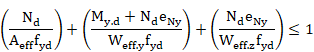
which is equivalent to:
Crt_TOT = Crt_N + Crt_My + Crt_Mz £ 1

- Output results are written in the CivilFEM results file as an alternative. Checking results: criteria and variables are described in the following table.
Checking of Members under Bending Moment + Axial Force and Bi-axial Bending + Axial Force
|
Result |
Concepts |
Description |
|
NED |
|
Design value of the axial force. |
|
MYED |
|
Design value of the bending moment about Y axis. |
|
MZED |
|
Design value of the bending moment about Z axis. |
|
NCRD |
|
Design compression resistance of the cross-section |
|
MNYRD |
|
Reduced design moment resistance of the cross-section about Y axis |
|
MNZRD |
|
Reduced design moment resistance of the cross-section about Z axis |
|
CRT_N |
|
Axial criterion |
|
CRT_MY |
|
Bending criterion along Y |
|
CRT_MZ |
|
Bending criterion along Z |
|
ALPHA |
α |
Alpha constant |
|
BETA |
β |
Beta constant |
|
CRT_TOT |
Crt_tot £ 1 |
IS 800:2007 global criterion |
|
CLASS |
|
Section Class |
|
AREA |
|
Area of the section utilized (Gross or Effective) |
|
WY |
|
Used section Y modulus (Elastic, Plastic or Effective) |
|
WZ |
|
Used section Z modulus (Elastic, Plastic or Effective) |
|
SIGXED |
|
Maximum longitudinal stress |
|
ENY |
|
Shift of the Z axis in Y direction |
|
ENZ |
|
Shift of the Y axis in Z direction |
|
USE_MY |
|
Modified design value of the bending moment about Y axis |
|
USE_MZ |
|
Modified design value of the bending moment about Z axis |
|
PARM_N |
n |
Parameter n |
Corresponds to chapter 8 in IS-800-2007.
- Forces and moments selection.
The forces and moments considered in this checking type are:
|
|
Design value of the axial force (positive if compressive, otherwise element is not processed). Represented as Pd . |
- Class definition and effective section properties calculation.
The section class is determined by the sections general processing with the
previously selected forces and moments if the selected option is partial, or
with all the forces and moments if the selected option is full. The entire
calculation is accomplished with the gross section properties.
- Criteria calculation.
When checking the buckling of compression members, the criterion is given by:
![]() à
à ![]()
where:
|
|
Design buckling resistance.
|
|
|
Reduction factor for the relevant buckling mode, the program does not consider the torsional or the lateral-torsional buckling. |
The c calculation in members of constant cross-section may be determined from:

![]()
where a is an imperfection factor that depends on the buckling curve. This curve depends on the cross-section type, producing the following values for a:
Imperfection factor a for IS-800-2007
|
Section type |
Limits |
Buckling axis |
Buckling curve |
a |
|
Rolled I |
h/b>1.2 and tf |
y – y |
a |
0.21 |
|
Rolled I |
h/b>1.2 and tf |
z – z |
b |
0.34 |
|
Rolled I |
h/b>1.2 and 40mm<t |
y – y |
b |
0.34 |
|
Rolled I |
h/b>1.2 and 40mm<tf |
z – z |
c |
0.49 |
|
Rolled I |
h/b |
y – y |
b |
0.34 |
|
Rolled I |
h/b |
z – z |
c |
0.49 |
|
Rolled I |
tf>100mm |
y – y |
d |
0.76 |
|
Rolled I |
tf>100mm |
z – z |
d |
0.76 |
|
|
||||
|
Welded I |
tf |
y – y |
b |
0.34 |
|
Welded I |
tf |
z – z |
c |
0.49 |
|
Welded I |
tf >40mm |
y – y |
c |
0.49 |
|
Welded I |
tf >40mm |
z – z |
d |
0.76 |
|
|
||||
|
Rolled box and pipe |
- |
Any |
a |
0.21 |
|
Welded box and pipe (Using fyb) |
- |
Any |
b |
0.34 |
|
|
||||
|
Welded box in other case |
- |
Any |
b |
0.34 |
|
Welded box |
b/tf <30 |
y – y |
c |
0.49 |
|
Welded box |
h/tw <30 |
z – z |
c |
0.49 |
|
U, L and T |
- |
Any |
c |
0.49 |
![]()
Where ![]() is the elastic critical force for the relevant buckling mode. (See
section for Critical Forces and Moments Calculation).
is the elastic critical force for the relevant buckling mode. (See
section for Critical Forces and Moments Calculation).
The elastic critical axial forces are calculated in the planes XY (![]() ) and XZ (
) and XZ (![]() ) and the
corresponding values of
) and the
corresponding values of ![]() and
and ![]() , taking the smaller one as the final value for c.
, taking the smaller one as the final value for c.
![]()
- Output results are written in the CivilFEM results file as an alternative. Checking results: criteria and variables are described in the following table.
Checking for Buckling of Compression Members
|
Result |
Concepts |
Description |
|
NED |
|
Design value of the compressive force. |
|
NBRD |
|
Design buckling resistance of a compressed member. |
|
CRT_CB |
|
Compression buckling criterion. |
|
CRT_TOT |
|
IS 800:2007 global criterion. |
|
CHI |
|
Reduction factor for the relevant buckling mode. |
|
BETA_A |
|
Ratio of the used area to gross area. |
|
AREA |
A |
Area of the gross section. |
|
CHI_Y |
|
Reduction factor for the relevant My buckling mode. |
|
CHI_Z |
|
Reduction factor for the relevant Mz buckling mode. |
|
CLASS |
|
Section Class. |
|
PHI_Y |
|
Parameter Phi for bending My. |
|
PHI_Z |
|
Parameter Phi for bending Mz. |
|
LAM_Y |
|
Non-dimensional reduced slenderness for bending My. |
|
LAM_Z |
|
Non-dimensional reduced slenderness for bending Mz. |
|
NCR_Y |
|
Elastic critical force for the relevant My buckling mode. |
|
NCR_Z |
|
Elastic critical force for the relevant Mz buckling mode. |
|
ALP_Y |
|
Imperfection factor for bending My. |
|
ALP_Z |
|
Imperfection factor for bending Mz. |
Corresponds to chapter 9.3 in IS-800-2007.
- Forces and moments selection.
The forces and moments considered for this checking type are:
|
|
Design value of the axial force (positive if tensile, otherwise element not processed if compressive). |
|
|
Design value of the bending moment about the relevant bending axis. |
- Class definition and effective section properties calculation.
The section class is determined by the general processing of sections with the
previously selected forces and moments if the selected option is partial, or
with all the forces and moments if the selected option is full. The entire
calculation is accomplished with the gross section properties.
- Criteria calculation.
With checking lateral-torsional buckling of members subjected to combined
bending and axial tension, the value of the axial force is multiplied by a
reduction factor
![]() in order to consider
the axial force and bending moment as a vector magnitude.
in order to consider
the axial force and bending moment as a vector magnitude.
The value of ![]() depends on the
country where the code will be applied. That factor is introduced as a property
at member level, and typically its value is equal to:
depends on the
country where the code will be applied. That factor is introduced as a property
at member level, and typically its value is equal to: ![]() = 0.8
= 0.8
The stress in the extreme compression fiber is calculated as follows:
![]()
Where ![]() is the elastic
section modulus for the extreme compression fiber and
is the elastic
section modulus for the extreme compression fiber and ![]() is the design value
of the axial tension.
is the design value
of the axial tension.
The verification equation is derived to:
![]() à
à ![]()
Where:
![]()
- Output results are written in the CivilFEM results file as an alternative. Checking results: criteria and variables are described in the following table.
Checking Lateral-Torsional Buckling of Members Subjected to Combined Bending and Axial Tension
|
Results |
Concepts |
Description |
|
NTSD |
|
Design value of the axial tension. |
|
MSD |
|
Design value of the bending moment. |
|
MEFFSD |
|
Effective design internal moment. |
|
MBRD |
|
Buckling resistance moment of a laterally unrestrained beam. |
|
CRT_LT |
|
Lateral-torsional buckling criterion. |
|
CRT_TOT |
|
IS 800:2007 global criterion. |
|
CLASS |
|
Section Class. |
|
WCOM |
|
Elastic section modulus for the extreme compression fiber. |
|
SCOMED |
|
Net calculated stress in the extreme compression fiber. |
|
CHI_LT |
|
Reduction factor for lateral-torsional buckling. |
|
BETA_W |
|
Ratio of the used modulus to plastic modulus. |
|
WPL |
|
Plastic modulus. |
|
PHI_LT |
|
Parameter Phi for lateral-torsional buckling. |
|
LAM_LT |
|
Esbeltez adimensional reducida. |
|
MCR |
|
Elastic critical moment for lateral-torsional buckling. |
|
ALP_LT |
|
Non-dimensional reduced slenderness. |
Corresponds to chapter 9.3 in IS-800-2007.
- Forces and moments selection.
The forces and moments considered in this checking type are:
|
|
Design value of the axial compression (positive if compressive, otherwise element not processed if tensile). |
|
|
Design value of the bending moment about the relevant axis of bending. |
|
|
Design value of the bending moment about the secondary axis of bending. |
- Class definition and effective section properties calculation.
The section class is determined by the general processing of sections with the
previously selected forces and moments if the selected option is partial, or
with all the forces and moments if the selected option is full. The entire
calculation is accomplished with the gross section properties.
- Criteria calculation.
When checking the lateral-torsional buckling of members subjected to combined bending and axial compression, the criterion to satisfy is as follows:

à Crt_TOT = Crt_N + Crt_My + Crt_Mz £ 1
where:
|
Crt_TOT |
IS 800:2007 global criterion. |
|
|
Axial criterion. |
|
|
Bending criterion (principal axis). |
|
|
Bending criterion (secondary axis). |
|
|
Design buckling resistance for compression. |
|
|
Design buckling resistance moment (principal axis) |
|
|
Design buckling resistance moment (secondary axis). |
The member resistances depend on the cross-section class and on the possibility that the lateral-torsional buckling is a potential failure mode for the structure.
Members with class 1 and 2 cross-sections shall satisfy:

where:


![]() =
=![]()
![]()
Where:
|
|
are the reduction factors defined at the section corresponding to Checking for Buckling of Compression Members. |
|
|
are equivalent uniform moment factors for flexural bending. These factors are entered as properties at member level. (See section Data at Member Level, factors BetaMy and BetaMz). |
Members with Class 1 and 2 cross-sections for which lateral-torsional buckling is a potential failure mode shall satisfy:

where:

![]()
where ![]() is an equivalent uniform moment factor for lateral-torsional
buckling. This factor, as the precedent factors CMy and CMz.
is an equivalent uniform moment factor for lateral-torsional
buckling. This factor, as the precedent factors CMy and CMz.
Members with Class 3 cross-sections shall satisfy:
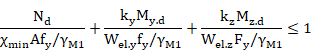
where ky, kz and cmin are as for Class 1 and 2 cross-sections.
![]()
![]()
Members with Class 3 cross-sections for which lateral-torsional buckling is a potential failure mode shall satisfy:

Members with Class 4 cross-sections shall satisfy:

where:
|
|
are the same as for class 1 and 2 cross-sections, but use the
effective area |
|
|
are the same as for class 3 cross-sections, but add the moment |
|
|
are defined in the section corresponding to Checking of members under bending and axial force and bi-axial bending. |
Members with Class 4 cross-sections for which lateral-torsional buckling is a potential failure mode shall satisfy:

where:
|
|
is similar to class 1 and 2 cross-sections, but uses the effective area Aeff, instead of the gross area A. |
|
|
is similar to class 2 cross-sections, but adds the moment |
Checking Parameters:
|
Class |
A |
|
|
|
|
|
|
|
1 |
A |
|
|
0.6 |
0.6 |
0 |
0 |
|
2 |
A |
|
|
0.6 |
0.6 |
0 |
0 |
|
3 |
A |
|
|
0.8 |
1 |
0 |
0 |
|
4 |
|
|
|
0.8 |
1 |
Depending on members and stresses |
Depending on members and stresses |
Interaction Factors:
|
Class |
Section type |
|
|
|
|
1 y 2 |
I, H |
|
|
|
|
RHS |
|
|||
|
3 y 4 |
All sections |
|
|
|
where:
![]() y
y ![]() Limited
slenderness values for y-y and z-z axes, less than 1.
Limited
slenderness values for y-y and z-z axes, less than 1.
![]()
- Output results are written in the CivilFEM results file as an alternative. Checking results: criteria and variables are described in the following table.
Checking for Lateral-Torsional Buckling of Members Subjected to Bending and Axial Compression
|
Result |
Concepts |
Description |
|
NED |
|
Design value of the axial compression force. |
|
MYED |
|
Design value of the bending moment about Y axis. |
|
MZED |
|
Design value of the bending moment about Z axis. |
|
NBRD1 |
|
Design compression resistance of the cross-section. |
|
MYRD1 |
|
Reduced design moment resistance of the cross-section about Y axis. |
|
MZRD1 |
|
Reduced design moment resistance of the cross-section about Z axis. |
|
NBRD2 |
|
Design compression resistance of the cross-section. |
|
MYRD2 |
|
Reduced design moment resistance of the cross-section about Y axis. |
|
MZRD2 |
|
Reduced design moment resistance of the cross-section about Z axis. |
|
K_Y |
|
Parameter Ky. |
|
K_Z |
|
Parameter Kz. |
|
K_LT |
|
Parameter KLT. |
|
CRT_N1 |
|
Axial criterion. |
|
CRT_MY1 |
|
Bending Y criterion. |
|
CRT_MZ1 |
|
Bending Z criterion. |
|
CRT_1 |
CRT_N1+CRT_MY1 |
Criterion 1 |
|
CRT_N2 |
|
Axial criterion. |
|
CRT_MY2 |
|
Bending Y criterion. K=KyLT if torsion exists and if not present K=ayKy |
|
CRT_MZ2 |
|
Bending Z criterion. |
|
CRT_2 |
CRT_N2+CRT_MY2 |
Criterion 2 |
|
CRT_TOT |
Crt_tot £ 1 |
IS 800:2007 global criterion. |
|
CLASS |
|
Section Class. |
|
CHIMIN |
|
Reduction factor for the relevant buckling mode. |
|
CHI_Y |
|
Reduction factor for the relevant My buckling mode. |
|
CHI_Z |
|
Reduction factor for the relevant Mz buckling mode. |
|
CHI_LT |
|
Reduction factor for lateral-torsional buckling. |
|
AREA |
|
Used area of the section (Gross or Effective). |
|
WY |
|
Used section Y modulus (Elastic, Plastic or Effective). |
|
WZ |
|
Used section Z modulus (Elastic, Plastic or Effective). |
|
ENY |
|
Shift of the Z axis in Y direction. |
|
ENZ |
|
Shift of the Y axis in Z direction. |
|
NCR_Y |
|
Elastic critical force for the relevant My buckling mode. |
|
NCR_Z |
|
Elastic critical force for the relevant Mz buckling mode. |
|
MCR |
|
Elastic critical moment for lateral-torsional buckling. |
|
LAM_Y |
|
Non-dimensional reduced slenderness for bending My. |
|
LAM_Z |
|
Non-dimensional reduced slenderness for bending Mz. |
|
LAM_LT |
|
Non-dimensional reduced slenderness for lateral-torsional buckling. |
The critical forces and moments![]() ,
, ![]() and
and
![]() , are needed for the different types
of buckling checks. They are calculated based on the following formulation:
, are needed for the different types
of buckling checks. They are calculated based on the following formulation:


where:
|
|
Elastic critical axial force in plane XY. |
|
|
Elastic critical axial force in plane XZ. |
|
A |
Gross area. |
|
E |
Elasticity modulus. |
|
|
Member slenderness in plane XY. |
|
|
Member slenderness in plane XZ. |
|
|
Radius of gyration of the member in plane XY. |
|
|
Radius of gyration of the member in plane XZ. |
|
|
Buckling length of member in plane XY. |
|
|
Buckling length of member in plane XZ. |
The buckling length in both planes is the length between the ends restrained against lateral movement and it is obtained from the member properties, according to the following expressions:
![]()
![]()
where:
|
Cfbuckxy |
Buckling factor in plane XY. |
|
Cfbuckxz |
Buckling factor in plane XZ. |
For the calculation of the elastic critical moment for lateral-torsional buckling, Mcr, the following equation shall be used. This equation is only valid for uniform symmetrical cross-sections about the minor axis (Annex E, IS 800:2007). IS 800:2007 does not provide a method for calculating this moment in nonsymmetrical cross-sections or sections with other symmetry plane (angles, channel section, etc.).


where:
|
|
Elastic critical moment for lateral-torsional buckling. |
|
|
Factors depending on the loading and end restraint conditions. |
|
k, |
Effective length factors. |
|
E |
Elasticity modulus. |
|
|
Moment of inertia about the principal axis. |
|
|
Moment of inertia about the minor axis. |
|
L |
Length of the member between end restraints. |
|
G |
Shear modulus. |
|
|
|
|
|
Coordinate of the point of load application. ANSYS always
considers that the load is applied at the center of gravity, therefore: |
|
|
Coordinate of the shear center. |
|
A |
Cross-section area. |
Factors C and k are read from the properties at member level.
The integration of the previous equation is calculated as a summation extending to each plate. This calculation is accomplished for each plate according to its ends coordinates:
![]() ,
,![]() and
and ![]() ,
,![]() and its
thicknesses.
and its
thicknesses.

where:
![]() = thickness of
plate i
= thickness of
plate i
![]()
![]()
![]()
![]()
![]() = plate width
= plate width

With CivilFEM it is possible to perform the following checking and analysis types:
|
- Tension |
Section 6.8.2 |
|
- Flexure |
6.12.2.2, A6 |
|
- Shear Force |
6.10.9 |
|
- Flexure and axial force |
6.9.2.2, 6.8.2.3 |
|
- Bending plus axial force |
6.9.2.2, 6.8.2.3 |
|
- Compression members |
6.9.4.1.2 |
|
- Compression members |
6.9.4.1.3 |
For AASHTO LRFD BRIDGE DESIGN SPECIFICATIONS 2010 checking, the following material properties are used:
|
Description |
Property |
|
Steel yield strength |
Fy(th) |
|
Ultimate strength |
Fu(th) |
|
Elasticity modulus |
E |
|
Poisson coefficient |
n |
|
Shear modulus |
G |
Necessary steps to conduct the different checks in CivilFEM are as follows:
a) Obtain material properties corresponding to the element stored in CivilFEM database and calculate the rest of the properties needed for checking:
Properties obtained from CivilFEM database:
Elasticity modulus E
Poisson’s ratio : ν
Yield strength: Fy (th)
Ultimate strength Fu (th)
Shear modulus G
Thickness of corresponding plate th
b) Obtain the cross-sectional data corresponding to the element.
c) Initiate the values of the plate’s reduction factors and the other plate’s parameters to determine its class.
d) Perform a check of the section according to the type of external load.
e) Results. In CivilFEM.
The required data for the different checking types are provided within tables found in their corresponding section of this manual.
Steel sections are classified for flexure as compact, noncompact or slender-element sections. For a section to qualify as compact its flanges must be continuously connected to the web or webs and the width-thickness ratios of its compression elements must not exceed the limiting width-thickness ratios lp. If the width-thickness ratio of one or more compression elements exceeds lp but does not exceed lr, the section is noncompact. If the width-thickness ratio of any element exceeds lr, the section is referred to as a slender-element compression section. Compression classification is similar but with only one ratio to distinguish slender and non-slender sections
Therefore, the code suggests different lambda values depending on if the element is subjected to compression, flexure or compression plus flexure.
The section classification is the worst-case scenario of all of its plates. Therefore, the class is calculated for each plate with the exception of pipe sections, which have their own formulation because it cannot be decomposed into plates. This classification will consider the following parameters:
a) Length of elements:
The program will define the element length (b or h) as the length of the plate (distance between the extreme points), except when otherwise specified.
b) Flange or web distinction:
To distinguish between flanges or webs, the program follows the criteria below:
Once the principal axis of bending is defined, the program will examine the plates of the section. Fields Pty and Ptz of the plates indicate if they behave as flanges, webs or undefined, choosing the correct one for the each axis. If undefined, the following criterion will be used to classify the plate as flange or web: if |Dy|<|Dz| (increments of end coordinates) and flexure is in the Y axis, it will be considered a web; if not, it will be a flange. The reverse will hold true for flexure in the Z-axis.
· Hot rolled Steel Shapes:
Section I and C:
The length of the plate h will be taken as the value d for the section dimensions.
Section Box:
The length of the plate will be taken as the width length minus three times the thickness.
In order to check for compression it is necessary to determine if the element is stiffened or unstiffened.
- For stiffened elements:

Pipe sections
![]()
Box sections

- Unstiffened elements:

Angular sections

Stem of T sections

The bending check is only applicable to very specific sections. Therefore, the slenderness factor is listed for each section:
· Section I:
Flanges:
![]()
![]()
For hot rolled shapes ![]()
For welded
sections ![]() ,
, ![]()
![]() = minimum of 0.7
= minimum of 0.7![]() ,
, ![]() /
/![]() y
y ![]() but no less than
0.5
but no less than
0.5![]() .
.
Web:


· Section C
Flanges:
![]()
![]()
For hot rolled
shapes ![]()
For welded
sections![]() ,
, ![]()
![]() = minimum of
= minimum of ![]() y
y ![]() but no less than
but no less than ![]() .
.
Web:

· Pipe section:
![]()
![]()
· Box section:
Flanges of box section:


Webs: the program distinguishes between the flange and web upon the principal axis chosen by the user.

· T section:
Flange: ![]()

Web: No limits are included for flexure classification, so class section is only checked for flange limit.
The axial tension force must be taken as positive (if the tension force has a negative value, the element will not be checked)
The factored tensile resistance, ![]() , shall be taken as the lesser of :
, shall be taken as the lesser of :
a) yielding in the gross section:
![]()
![]()
b) rupture in the net section:
![]()
![]()
Being:
|
|
Effective net area. |
|
|
Gross area. |
|
|
Minimum yield stress. |
|
|
Minimum tensile strength. |
Values of Rp and U must be introduced by the user according article 6.8.2.1.
The effective net area will be taken as Ag – AHOLES. The user will need to enter the correct value for AHOLES (the code indicates that the diameter is 1/16th in. (2 mm) greater than the real diameter).
Axial compression check by la AASHTO
LRFD BRIDGE DESIGN SPECIFICATIONS 2010 of the design compressive strength, ![]() , are determined as follows:
, are determined as follows:
![]()
Compressive Strength for Flexural Buckling
Compressive Strength for Flexural Buckling
![]()
(a) for ![]()
![]()
(b) for ![]()
![]()
Being:
![]()

Where:
|
|
Gross area of member. |
|
Q |
Slender element reduction factor. |
|
|
Governing radius of gyration about the buckling axis. |
|
K |
Effective length factor. |
|
l |
Unbraced length. |
Factor Q for compact and noncompact
sections is always 1. Nevertheless, for slender sections ( exceed ratio given
in 10-G.6.1.1 ) , the value of ![]() has a particular
procedure. Such procedure is described below:
has a particular
procedure. Such procedure is described below:
Factor Q for slender sections:
For unstiffened plates, Qs must be calculated and for stiffened plates, Qa must be determined. If these cases do not apply (box sections or angular sections, for example), a value of 1 for these factors will be taken.
For circular sections, there is a particular procedure of calculating Q. Such procedure is described below:
· For circular sections, Q is:
![]()
![]()
Factor Qs:
If there are several plates free, the value of Qs is taken as the biggest value of all of them. The program will check the slenderness of the section in the following order:
· Angular
|
If |
|
|
|
If |
|
|
· Stem of T
|
If |
|
|
|
If |
|
|
· Rolled shapes
|
If |
|
|
|
If |
|
|
· Other sections
|
If |
|
|
|
If |
|
|
Where l is the element slenderness and
|
|
For hot rolled I sections |
|
|
for other sections |
Factor Qa:
The calculation of factor Qa is an iterative process. Its procedure is the following:
7) An initial value of Q equal to Qs calculated before is taken.
8) With this value f = QsFy is calculated.
9) For elements with stiffened plates, the effective width be is calculated.
10) With be the effective area is calculated.
11) With the value of the effective area, Qa is calculated.
![]()
· For a box section
|
If |
|
|
· For other sections
|
If |
|
|
If it is not within those limits, ![]()
With the be values for each plate, the part that does not contribute [t·(b‑be)] is subtracted from the area (where t is the plate thickness). Using this procedure, the effective area is calculated.
Finally, with Qs and Qa, Q is calculated.
Output results are written in the CivilFEM results file.
Compressive Strength for Flexural-Torsional Buckling
This type of check can be carried out for compact sections as well as for noncompact or slender sections. The steps for these three cases are as follows:
Nominal compressive strength, ![]() :
:
(a) for ![]()
![]()
(b) for ![]()
![]()
Where:
![]()
![]()
Factor Q for compact and noncompact sections is 1. Nevertheless, for slender sections, the Q factor has a particular procedure of calculation. Such procedure is equal to the one previously described.
The elastic stress for critical torsional
buckling or flexural-torsional buckling ![]() is calculated as
the lowest root of the following third degree equation, in which the axis have
been changed to adapt to the CivilFEM normal axis:
is calculated as
the lowest root of the following third degree equation, in which the axis have
been changed to adapt to the CivilFEM normal axis:
![]() (6.9.4.1.3-7)
(6.9.4.1.3-7)
Where:
|
|
Effective length factor for torsional buckling. |
|
G |
Shear modulus (MPa). |
|
|
Warping constant (mm6). |
|
J |
Torsional constant (mm4). |
|
|
Moments of inertia about the principal axis (mm4). |
|
|
Coordinates of shear center with respect to the center of gravity (mm). |
![]()


![]()

where:
|
A |
Cross-sectional area of member. |
|
l |
Unbraced length. |
|
|
Effective length factor, in the z and y directions. |
|
|
Radii of gyration about the principal axes. |
|
|
Polar radius of gyration about the shear center. |
In this formula, CivilFEM principal axes are used. If the CivilFEM axes are the principal axes ±5º sexagesimal degrees, Ky and Kz are calculated with respect to the Y and Z-axes of CivilFEM. If this is not the case (angular shapes, for example) axes U and V will be used as principal axes, with U as the axis with higher inertia.
Output results are written in the CivilFEM results file.
Summary of the checks done by CivilFEM:
|
SECTION TYPE |
YIELDING |
LTB |
FLB |
WLB |
Conditions |
|
BOX |
X (6.12.2.2.2) |
|
X (6.12.2.2.2) |
X (6.12.2.2.2) |
Non-slender web |
|
PIPE |
X (6.12.2.2.3) |
|
X(local buckling) (6.12.2.2.3) |
|
Compact, non-compact and slender under the limit for flexure check. |
|
T SECTION |
X (6.12.2.2.4) |
X (6.12.2.2.4) |
X (6.12.2.2.4) |
X (6.12.2.2.4) |
Non-slender flange |
|
I SECTION (FLEXUREABOUT STRONG AXIS) |
X |
X (A.6.3.3) |
X (A.6.3.2) |
|
Non-slender web and Fy<70 ksi
|
|
DOUBLE T (FLEXURE ABOUT WEAK AXIS) |
X |
|
X (6.12.2.2.1) |
|
Non-slender flanges |
|
SECTION C (FLEXURE ABOUT STRONG AXIS) |
X (6.12.2.2.5) |
X (6.12.2.2.5) |
|
|
Compact members |
|
SECTION C (FLEXURE ABOUT WEAK AXIS) |
X
|
|
X (6.12.2.2.5) |
|
Non-slender flanges |
The design flexural strength, ff Mn, shall be determined as follows:
ff = 1.00
Where Mn is the lowest value of four checks:
e) Yielding (Y)
f) Lateral-torsional buckling (LTB)
g) Flange local buckling (FLB)
h) Web local buckling (WLB)
The checks done depends on the section:
·
Box ![]() (non-slender webs)
(non-slender webs)
· Yielding
![]() =
= ![]()
· FLB
If
![]()
![]()

If![]()
![]()
![]()
· WLB
If
![]()

·
Circular tubes ![]() (compact,
non-compact and slender under the ratio limit
(compact,
non-compact and slender under the ratio limit
![]() )
)
1. Yielding
![]()
2. Local buckling
If ![]()
![]()
If
![]()
![]()
![]()
·
T shape ![]()
1.
Yielding ![]()
If stem is in tension, the limit on ![]() is 1.6
is 1.6![]()
If stem is in compression ![]() is limited to
is limited to ![]()
2. LTB
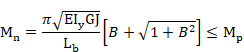

(The plus sign for B shall apply when the stem is in tension and the minus sign shall apply when the stem is in compression)
3. FLB
If![]()
![]()
![]() : Elastic section
modulus with respect to the compression flange
: Elastic section
modulus with respect to the compression flange
![]() is not provided because the limiting slenderness value
is larger than 12 (Eq. 6.10.2.2-1)
is not provided because the limiting slenderness value
is larger than 12 (Eq. 6.10.2.2-1)
4. Local buckling of the stem
![]()
·
I shape loaded on the strong axis ![]() (non-slender web)
(non-slender web)
1. Yielding
![]() =
= ![]()
2. LTB


Where:

![]()
![]()
![]()
![]()
![]()
![]()
![]() =
=
3. FLB
If
![]()
![]()
If ![]()
![]()
![]() is the web plastification factor for the compression
flange determined as specified in Article A6.2.1 or Article A6.2.2:
is the web plastification factor for the compression
flange determined as specified in Article A6.2.1 or Article A6.2.2:
If
is compact web 

If
is non-compact web, ![]()
![]()
![]() is the hybrid factor and for sections that are checked
in CivilFEM takes a value of 1.
is the hybrid factor and for sections that are checked
in CivilFEM takes a value of 1.
·
T shape loaded on weak axis ![]() (flanges compact or non-compact)
(flanges compact or non-compact)
1. Yielding:
![]() =
= ![]()
2. FLB
If
![]()
![]() =
=![]()
If ![]()
![]() =
=
![]()
·
C shape loaded on the strong axis ![]() ( web and flanges compact)
( web and flanges compact)
1. Yielding
![]() =
= ![]()
2. LTB


If ![]() <
<![]() <
<![]()
![]()
If ![]() >
>![]()
![]() =
=![]()


Where:
![]() = radius of gyration
about the weak axis(in)
= radius of gyration
about the weak axis(in)
J = Torsional constant St. Venant (in4)
![]() = Elastic section
modulus about strong axis(in3)
= Elastic section
modulus about strong axis(in3)
![]() = distance between
centroids of the flanges(in)
= distance between
centroids of the flanges(in)
![]() =warping constant(in6)
=warping constant(in6)
![]() =Moment gradient
modifier. Must be introduced by the user.
=Moment gradient
modifier. Must be introduced by the user.
·
C shape loaded on the weak axis ![]() (flanges compact or non-compact)
(flanges compact or non-compact)
1. Yielding
![]() = min (
= min (![]() , 1.6
, 1.6![]() )
)
2. FLB
If
![]()
![]() =
= ![]()
If![]()

Output results are written in the CivilFEM results file.
The design shear strength, ![]() , shall be
determined as follows:
, shall be
determined as follows:
For all provisions: ![]()
To calculate the nominal shear strength CivilFEM follows the provisions of the article 6.10.9.2 except for box-shaped (6.12.1.2.3b) and circular tubes (6.12.1.2.3c)
![]() =
=![]()
![]() =
=![]() , where D is total
depth of the web.
, where D is total
depth of the web.
C is the ratio of the shear-buckling resistance to the shear yield strength determined as:
a.
For ![]()
![]() = 1.0 (AASHTO 6.10.9.3.2-4)
= 1.0 (AASHTO 6.10.9.3.2-4)
b.
For ![]()
![]() (AASHTO 6.10.9.3.2-5)
(AASHTO 6.10.9.3.2-5)
c.
For ![]()
 (AASHTO 6.10.9.3.2-6)
The web plate buckling coefficient, Kv, will be calculated as a constant equal to 5.0.
For shape-box sections D is the clear distance between flanges less inside corner radius on each side. Both webs area shall be considered effective in resisting the shear.
For circular tubes the nominal shear strength will be taken as:
![]()
![]() , shear buckling
resistance (ksi)taken as the larger of either:
, shear buckling
resistance (ksi)taken as the larger of either:

![]()

![]()
Output results are written in the CivilFEM results file.
Checking of Members Subject to Flexure and Axial Tension / Compression
For this check, it is first necessary to determine the value of Mn. This value comes into play in the checking of formulas. The value of Mn, will be calculated in the same way as members subjected to flexure; thus, the nominal flexure strength (Mn) is the minimum of four checks:
1. Yielding
2. Lateral-torsional buckling
3. Flange local buckling
4. Web local buckling
In the case of having bending plus tension or bending plus compression, the interaction between flexure and axial force is limited by the following equations:
(c) For ![]()
![]()
![]() (6.8.2.3-2,
6.9.2.2-2)
(6.8.2.3-2,
6.9.2.2-2)
(d) For ![]()
![]() (6.8.2.3-1,
6.9.2.2-1)
(6.8.2.3-1,
6.9.2.2-1)
Where:
|
|
Axial force resulting from factored loads. |
|
|
Factored resistance. |
|
|
Moment resulting from factored loads. |
|
|
Factored flexural resistance . |
|
y |
Strong axis bending. |
|
z |
Weak axis bending. |
The following checks are carried out by CivilFEM:
If one of these checks do not meet the code requirements, it will not be possible to check the member under flexure plus tension / compression.
Output results are written in the CivilFEM results file
For AISC 13th Edition checking, the following material properties are used:
|
Description |
Property |
|
Steel yield strength |
Fy(th) |
|
Ultimate strength |
Fu(th) |
|
Elasticity modulus |
E |
|
Poisson coefficient |
n |
|
Shear modulus |
G |
*th =thickness of the plate
AISC 14th Edition considers the following data set for the section:
- Gross section data
- Net section data
- Effective section data.
- Data belonging to the section and plates class.
Gross section data correspond to the nominal properties of the cross-section. For the net section, only the area is considered. This area is calculated by subtracting the holes for screws, rivets and other holes from the gross section area. (The area of holes is introduced within the structural steel code properties).
The effective section data and the section and plates class data are obtained in the checking process according to chapter B, section B4 of the code. This chapter classifies steel sections into three groups (compact, noncompact and slender), depending upon the width-thickness ratio and other mandatory limits.
The AISC 14TH Edition module utilizes the gross section data in user units and the CivilFEM axis or section axis as initial data. The program calculates the effective section data and the class data, and stores them in CivilFEM’s results file, in user units and in CivilFEM or section axis.
The section data used in AISC 14TH Edition are shown in the following tables:
|
Description |
Data |
|
Input data: 1.- Height 2.- Web thickness 3.- Flanges thickness 4.- Flanges width 5.- Distance between flanges 6.- Radius of fillet (Rolled shapes) 7.- Toe radius (Rolled shapes) 8.- Weld throat thickness (Welded shapes) 9.- Web free depth |
H Tw Tf B Hi r1 r2 a d |
|
Output data |
(None) |
|
Description |
Data |
Reference axes |
|
Input data: 1.- Depth in Y 2.- Depth in Z 3.- Cross-section area 4.- Moments of inertia for torsion 5.- Moments of inertia for bending 6.- Product of inertia 7.- Elastic resistant modulus 8.- Plastic resistant modulus 9.- Radius of gyration 10.- Gravity center coordinates 11.- Extreme coordinates of the perimeter
12.- Distance between GC and SC in Y and in Z 13.- Warping constant 14.- Shear resistant areas 15.- Torsional resistant modulus 16.- Moments of inertia for bending about U, V 17.- Angle Y->U or Z->V |
Tky tkz A It Iyy, Izz Izy Wely, Welz Wply, Wplz iy, iz Ycdg, Zcdg Ymin, Ymax, Zmin, Zmax Yms, Zms Iw Yws, Zws Xwt Iuu, Ivv a |
CivilFEM CivilFEM
CivilFEM CivilFEM CivilFEM CivilFEM CivilFEM CivilFEM Section Section
Section
CivilFEM CivilFEM Principal CivilFEM |
|
Output data: |
(None) |
|
|
Description |
Data |
|
Input data: 1.- Gross section area 2.- Area of holes |
Agross Aholes |
|
Output data: 1.- Cross-section area |
Anet |
The effective section depends upon the geometry of the section; thus, the effective section is calculated for each element and each of the ends of the element.
|
Description |
Data |
|
Input data: |
(None) |
|
Output data: 1.- Reduction factor 2.- Reduction factor 3.- Reduction factor |
Q Qs Qa |
For AISC 14th Edition checking, besides the section properties, more data are needed for bucling checks. These data are shown in the following table.
|
Description |
Data |
|
Input data: 1.- Unbraced length of member (global buckling) 2.- Effective length factors Y direction 3.- Effective length factors Z direction 4.- Effective length factors for torsional buckling 5.- Flexural factor relative to bending moment 6.- Length between lateral restraints |
L KY KZ KTOR Cb Lb |
|
Output data: 1.- Compression class 2.- Bending class |
CLS_COMP CLS_FLEX |
Necessary steps to conduct the different checks in CivilFEM are as follows:
f)
Obtain material properties corresponding to the
element stored in CivilFEM database and calculate the rest of the properties
needed for checking:
Properties obtained from CivilFEM database (materials):
|
Elasticity modulus |
E |
|
Poisson’s ratio |
v |
|
Yield strength |
Fy (th) |
|
Ultimate strength |
Fu (th) |
|
Shear modulus |
G |
|
Thickness of corresponding plate |
th |
g) Obtain the cross-sectional data corresponding to the element.
h) Initiate the values of the plate’s reduction factors and the other plate’s parameters to determine its class.
i) Perform a check of the section according to the type of external load.
j) Results. In CivilFEM, checking results for each element end are stored in the results file .CRCF
Design shall be performed in accordance with:
![]()
Where:
|
|
Required strength (LRFD). |
|
|
Nominal strength. |
|
|
Resistance factor. |
|
|
Design strength |
Design shall be performed in accordance with:
![]()
Where:
|
|
Required strength (ASD) |
|
|
Nominal strength. |
|
|
Safety factor |
|
|
Allowable strength |
Steel sections are classified as compact,
noncompact or slender-element sections for bending sections and slender or non
slender for compression sections. For a section to qualify as compact its
flanges must be continuously connected to the web or webs and the
width-thickness ratios of its compression elements must not exceed the limiting
width-thickness ratios ![]() (see table B4.1 of
AISC 14th Edition). If the width-thickness ratio of one or more
compression elements exceeds
(see table B4.1 of
AISC 14th Edition). If the width-thickness ratio of one or more
compression elements exceeds ![]() but does not exceed
but does not exceed![]() , the section is
noncompact. If the width-thickness ratio of any element exceeds
, the section is
noncompact. If the width-thickness ratio of any element exceeds![]() , (see table B4.1 of
AISC 14th Edition), the section is referred to as a slender-element
compression section.
, (see table B4.1 of
AISC 14th Edition), the section is referred to as a slender-element
compression section.
Therefore, the code suggests different lambda values depending on if the element is subjected to compression, flexure or compression plus flexure.
The section classification is the worst-case scenario of all of its plates. Therefore, the class is calculated for each plate with the exception of pipe sections, which have their own formulation because it cannot be decomposed into plates. This classification will consider the following parameters:
a) Length of elements:
The program will define the element length (b or h) as the length of the plate (distance between the extreme points), except when otherwise specified.
b) Flange or web distinction:
To distinguish between flanges or webs, the program follows the criteria below:
Once the principal axis of bending is defined, the program will examine the plates of the section. Fields Pty and Ptz of the plates indicate if they behave as flanges, webs or undefined, choosing the correct one for the each axis. If undefined, the following criterion will be used to classify the plate as flange or web:
If ![]() (increments of end
coordinates) and flexure is in the Y axis, it will be considered a web; if not,
it will be a flange. The reverse will hold true for flexure in the Z-axis.
(increments of end
coordinates) and flexure is in the Y axis, it will be considered a web; if not,
it will be a flange. The reverse will hold true for flexure in the Z-axis.
· Hot rolled Steel Shapes:
Section I and C:
The length of the plate h will be taken as the value d for the section dimensions.
Section Box:
The length of the plate will be taken as the width length minus three times the thickness.
In order to check for compression it is necessary to determine if the element is stiffened or unstiffened.
- For stiffened elements:
![]()
![]()
Pipe sections
![]()
Box sections
![]()
![]()
- Unstiffened elements:
![]()
![]()
Angular sections
![]()
Stem of T sections
![]()
The bending check is only applicable to very specific sections. Therefore, the slenderness factor is listed for each section:
· Section I and C:
![]()
![]()
|
|
69 MPa for hot rolled shapes (10 ksi) |
|
114 MPa for welded sections (16.5 ksi) |
![]() = minimum of (
= minimum of (![]() ) and (
) and (![]() ) where
) where ![]() and
and![]() are the
are the ![]() of flange and web
respectively.
of flange and web
respectively.
Flanges of rolled sections:
![]()
![]()
Flanges of welded sections:
![]()
![]()
Flange:
If ![]()
If ![]()
![]()
Always: ![]()
![]() is the compression
axial force (taken as positive). If in tension, it will be taken as zero.
is the compression
axial force (taken as positive). If in tension, it will be taken as zero.
· Pipe section:
![]()
![]()
Box section:
Flanges of box section:
![]()
![]()
Flanges: the program distinguishes between the flange and web upon the principal axis chosen by the user.
If ![]()
If ![]()
![]()
Always: ![]()
![]()
· T section:
![]()
Stem: ![]()
Flanges: ![]()
The axial tension force must be taken as positive (if the tension force has a negative value, the element will not be checked)
Design tensile strength ![]() and the allowable
tensile strength
and the allowable
tensile strength ![]() , of tension
members, shall be the lower value of :
, of tension
members, shall be the lower value of :
c) yielding in the gross section:
![]()
![]()
![]()
d) rupture in the net section:
![]()
![]()
![]() = 2.00 (ASD)
= 2.00 (ASD)
Being:
|
|
Effective net area. |
|
|
Gross area. |
|
|
Minimum yield stress. |
|
|
Minimum tensile strength. |
The effective net area will be taken as ![]() – AHOLES.
The user will need to enter the correct value for AHOLES (the code
indicates that the diameter is 1/16th in. (2 mm) greater than the
real diameter).
– AHOLES.
The user will need to enter the correct value for AHOLES (the code
indicates that the diameter is 1/16th in. (2 mm) greater than the
real diameter).
The design compressive strength, ![]() ,and the allowable
compressive strength,
,and the allowable
compressive strength, ![]() , are determined as follows:
, are determined as follows:
The nominal compressive strength, ![]() , shall be the lowest
value obtained according to the limit states of flexural buckling, torsional
buckling and flexural-torsional buckling.
, shall be the lowest
value obtained according to the limit states of flexural buckling, torsional
buckling and flexural-torsional buckling.
![]()
![]()
This type of check can be carried out for compact sections as well as for noncompact or slender sections. These three cases adhere to the following steps:
Nominal compressive strength, ![]() :
:
![]() (E3-1)
(E3-1)
![]()
d) For : ![]()
![]() =
=
e) for ![]()
![]()
Where:
|
|
Gross area of member. |
|
r |
Governing radius of gyration about the buckling axis. |
|
K |
Effective length factor. |
|
l |
Unbraced length. |
|
|
Elastic critical buckling stress |
Factor Q for compact and noncompact sections is always 1. Nevertheless, for slender sections, the value of Q has a particular procedure. Such procedure is described below:
Factor Q for slender sections:
For unstiffened plates, Qs must be calculated and for stiffened plates, Qa must be determined. If these cases do not apply (box sections or angular sections, for example), a value of 1 for these factors will be taken.
For circular sections, there is a particular procedure of calculating Q. Such procedure is described below:
· For circular sections, Q is:
![]()
![]()
Factor Qs:
If there are several plates free, the value of Qs is taken as the biggest value of all of them. The program will check the slenderness of the section in the following order:
· Angular
|
If |
|
|
|
If |
|
|
· Stem of T
|
If |
|
|
|
If |
|
|
· Rolled shapes
|
If |
|
|
|
If |
|
|
· Other sections
|
If |
|
|
|
If |
|
|
Where l is the element slenderness and
|
|
for I sections |
|
|
for other sections |
Factor Qa:
The calculation of factor Qa is an iterative process. Its procedure is the following:
12) An initial value of Q equal to Qs is taken.
13) With this value ![]() is calculated.
is calculated.
14) This ![]() value is taken to
calculate
value is taken to
calculate ![]()
15) For elements with stiffened plates, the effective width be is calculated.
16) With be the effective area is calculated.
17) With the value of the effective area, Qa is calculated, and the process starts again.
![]()
· For a box section
|
If |
|
|
· For other sections
|
If |
|
|
If it is not within those limits, ![]() = b
= b
With the ![]() values for each
plate, the part that does not contribute [t·(b‑
values for each
plate, the part that does not contribute [t·(b‑![]() )] is subtracted
from the area (where t is the plate thickness). Using this procedure, the
effective area is calculated.
)] is subtracted
from the area (where t is the plate thickness). Using this procedure, the
effective area is calculated.
Finally, with Qs and Qa, Q is calculated,
and ![]() is obtained.
is obtained.
Output results are written in the CivilFEM results file (.CRCF).
This type of check can be carried out for compact sections as well as for noncompact or slender sections. The steps for these three cases are as follows:
Nominal compressive strength,![]() :
:
![]()
f) for ![]()
![]()
(b) for ![]()
![]()
Where:
![]()
Factor Q for compact and noncompact sections is 1. Nevertheless, for slender sections, the Q factor has a particular procedure of calculation. Such procedure is equal to the one previously described.
The elastic stress for critical torsional
buckling or flexural-torsional buckling ![]() is calculated as
the lowest root of the following third degree equation, in which the axis have
been changed to adapt to the CivilFEM normal axis:
is calculated as
the lowest root of the following third degree equation, in which the axis have
been changed to adapt to the CivilFEM normal axis:
![]()
Where:
|
|
Effective length factor for torsional buckling. |
|
G |
Shear modulus (MPa). |
|
|
Warping constant (mm6). |
|
J |
Torsional constant (mm4). |
|
|
Moments of inertia about the principal axis (mm4). |
|
|
Coordinates of shear center with respect to the center of gravity (mm).
|
where:
|
A |
Cross-sectional area of member. |
|
l |
Unbraced length. |
|
|
Effective length factor, in the z and y directions. |
|
|
Radii of gyration about the principal axes. |
|
|
Polar radius of gyration about the shear center. |
In this formula, CivilFEM principal axes
are used. If the CivilFEM axes are the principal axes ±5º sexagesimal degrees, ![]() and
and ![]() are calculated with
respect to the Y and Z-axes of CivilFEM. If this is not the case (angular
shapes, for example) axes U and V will be used as principal axes, with U as the
axis with higher inertia.
are calculated with
respect to the Y and Z-axes of CivilFEM. If this is not the case (angular
shapes, for example) axes U and V will be used as principal axes, with U as the
axis with higher inertia.
The torsional inertia (Ixx in CivilFEM, J in AISC 13TH Edition) is calculated for CivilFEM sections, but not for captured sections. Therefore the user will have to introduce this parameter in the mechanical properties of CivilFEM.
Output results are written in the CivilFEM results file (.CRCF).
Chapter F is only applicable to members subject to simple bending about one principal axis.
The design flexural strength,![]() , and the allowable
flexural strength,
, and the allowable
flexural strength, ![]() , shall be
determined as follows:
, shall be
determined as follows:
For all provisions:![]() = 0.90 (LRFD)
= 0.90 (LRFD) ![]() = 1.67 (ASD)
= 1.67 (ASD)
Where ![]() is the lowest value
of four checks according to sections F2 through F12:
is the lowest value
of four checks according to sections F2 through F12:
i) Yielding
j) Lateral-torsional buckling
k) Flange local buckling
l) Web local buckling
The value of the nominal flexural strength with the following considerations:
|
Shape |
Limit State |
Mr |
Fcr |
l |
lp |
lr |
|
I, C loaded in the axis of higher inertia.
|
LTB |
|
|
|
|
|
|
FLB |
|
|
|
Class B4.1 |
Class B4.1 |
|
|
WLB |
|
N.A. |
|
Class B4.1 |
Class B4.1 |
|
Shape |
Limit State |
Mr |
Fcr |
l |
lp |
lr |
|
I, C loaded in the axis of lower inertia.
|
LTB |
N.A. |
N.A. |
N.A. |
N.A. |
N.A. |
|
FLB |
|
|
|
Class B4.1 |
Class B4.1 |
|
|
WLB |
N.A. |
N.A. |
N.A. |
N.A. |
N.A. |
|
Shape |
Limit State |
Mr |
Fcr |
l |
lp |
lr |
|
Box
|
LTB |
|
|
|
|
|
|
FLB |
|
|
|
Class B4.1 |
Class B4.1 |
|
|
WLB |
|
N.A. |
|
Class B4.1 |
Class B4.1 |
|
Shape |
Limit State |
Mr |
Fcr |
l |
lp |
lr |
Notes |
|
Pipe
|
LTB |
NA |
NA |
NA |
NA |
NA |
Limited by Class B4.1 |
|
FLB |
Slender:
Non-compact:
|
|
|
Class B4.1 |
Class B4.1 |
||
|
WLB |
NA |
NA |
NA |
NA |
NA |
|
Shape |
Limit State |
Mr |
Fcr |
l |
lp |
lr |
|
T, loaded in web plane
|
LTB |
|
N.A. |
N.A. |
N.A. |
N.A. |
|
FLB |
N.A. |
N.A. |
N.A. |
N.A. |
N.A. |
|
|
WLB |
N.A. |
N.A. |
N.A. |
N.A. |
N.A. |
Where:
(positive sign if the stem is under tension, negative if it is under compression)
In T sections: ![]() stem in tension;
stem in tension; ![]() stem in
compression.
stem in
compression.
For slender webs the nominal flexural
strength ![]() is the minimum of
the following checks:
is the minimum of
the following checks:
The first check uses the following formula:
![]()
where:
|
|
Section modulus referred to tension flange. |
|
|
Yield strength of tension flange. |
The second check uses the following formula:
![]()
where:
The critical stress depends upon different
slenderness parameters such as l, ![]() ,
, ![]() and
and ![]() in the following
way:
in the following
way:
|
For |
|
|
For |
|
|
For |
|
The slenderness values have to be calculated for the following limit states:
![]()
![]() (International System units)
(International System units)
![]() is the radius of
gyration of compression flange plus one third of the compression portion of the
web (mm).
is the radius of
gyration of compression flange plus one third of the compression portion of the
web (mm).
By default, the
program takes a conservative value of ![]() .
.
![]()
![]() (IS units)
(IS units)
where:
![]()
![]()
and
![]()
Between these two slenderness, the program will choose values the value that produces a lower critical stress.
Output results are written in the CivilFEM results file (.CRCF).
The design shear strength, ![]() , and the allowable
shear strength,
, and the allowable
shear strength, ![]() , shall be
determined as follows:
, shall be
determined as follows:
For all provisions: ![]() = 0.90 (LRFD)
= 0.90 (LRFD) ![]() = 1.67 (ASD)
= 1.67 (ASD)
According to the limit states of shear
yielding and shear buckling, the nominal shear strength, ![]() , of unstiffened webs is:
, of unstiffened webs is:
![]()
For webs of rolled I-shaped members with ![]() :
:
![]() = 1.00 (LRFD)
= 1.00 (LRFD) ![]() = 1.50 (ASD)
= 1.50 (ASD)
![]() = 1.0 (web shear
coefficient)
= 1.0 (web shear
coefficient)
For webs of all other doubly symmetric
shapes and singly symmetric shapes and channels ![]() is determined as
follows:
is determined as
follows:
![]() = 1.0
= 1.0
![]()
![]()
Where ![]() is the overall depth
times the web thickness.
is the overall depth
times the web thickness.
It is assumed that there are no stiffeners;
therefore, the web plate buckling coefficient ![]() will be calculated
as a constant equal to 5.0.
will be calculated
as a constant equal to 5.0.
Output results are written in the CivilFEM results file (.CRCF).
For this check, it is first necessary to
determine the value of Mn. This value comes into play in the checking of
formulas. The value of Mn, will be calculated in the same way as
members subjected to flexure; thus, the nominal flexure strength (![]() ) is the minimum of
four checks:
) is the minimum of
four checks:
5. Yielding
6. Lateral-torsional buckling
7. Flange local buckling
8. Web local buckling
In the case of having bending plus tension or bending plus compression, the interaction between flexure and axial force is limited by the following equations:
(e) For ![]()
![]() (H1-1a)
(H1-1a)
(f)
For ![]()
![]() (H1-1b)
(H1-1b)
If the axial force is tension:
|
|
Required tensile strength (N). |
|
|
Available tensile strength (N):
|
|
|
Required flexural strength (N·mm). |
|
|
Available flexural strength (N·mm): Design: Allowable: |
|
y |
Strong axis bending. |
|
z |
Weak axis bending. |
|
|
Resistance factor for tension (Sect.D2) |
|
|
Resistance factor for flexure = 0.90 |
|
|
Safety factor for tension (Sect D2) |
|
|
Safety factor for flexure = 1.67 |
If the axial force is compression:
|
|
Required compressive strength (N). |
|
|
Available compressive strength (N): Design: Allowable: |
|
|
Required flexural strength (N·mm). |
|
|
Available flexural strength (N·mm): Design: Allowable: |
|
Y |
Strong axis of bending. |
|
Z |
Weak axis of bending. |
|
|
Resistance factor for compression =0.90 |
|
|
Resistance factor for flexure = 0.90 |
|
|
Safety factor for compression =1.67 |
|
|
Safety factor for flexure = 1.67 |
The following checks are carried out by CivilFEM:
If one of these checks do not meet the code requirements, it will not be possible to check the member under flexure plus tension / compression.
Output results are written in the CivilFEM results file (.CRCF).
The design torsional strength, fTTn , and the allowable torsional strength, Tn/ΩT , shall be the lowest value obtained according to the limit states of yielding under normal stress, shear yielding under shear stress or buckling, determined as follows:
![]() = 0.90 (LRFD)
= 0.90 (LRFD) ![]() = 1.67 (ASD)
= 1.67 (ASD)
· For the limit state of yielding, under normal stress:
![]()
· For the limit state of yielding, under shear stress:
![]()
· For the limit state of buckling:
![]()
-
Where ![]() is calculated
is calculated
Output results are written in the CivilFEM results file (.CRCF).
For checking steel structures according to Structural code (Annex 22) in CivilFEM, it is possible to check structures composed by welded or rolled shapes under axial forces, shear forces and bending moments in 3D.
With CivilFEM it is possible to accomplish the following check and analysis types:
|
Check steel sections subjected to |
|
|
- Tension |
Art. 6.2.3 |
|
- Compression |
Art. 6.2.4 |
|
- Bending |
Art. 6.2.5 |
|
- Shear force |
Art. 6.2.6 |
|
- Bending and Shear |
Art. 6.2.8 |
|
- Bending and axial force |
Art. 6.2.9 |
|
- Bending, shear and axial force |
Art. 6.2.10 |
|
Check for buckling |
|
|
- Compression members with constant cross-section |
Art. 6.3.1 |
|
- Lateral-torsional buckling of beams |
Art. 6.3.2 |
|
- Members subjected to bending and axial tension |
N/A |
|
- Members subjected to bending and axial compression |
Art. 6.3.3 |
Valid cross-sections supported by CivilFEM for checks according to Structural code are the following:
![]() All rolled shapes included in the program
libraries (see the hot rolled shapes library).
All rolled shapes included in the program
libraries (see the hot rolled shapes library).
![]() The following welded beams: double T shapes, U
or channel shapes, T shapes, box, equal and unequal legs angles and pipes.
The following welded beams: double T shapes, U
or channel shapes, T shapes, box, equal and unequal legs angles and pipes.
![]() Structural steel sections defined by plates.
Structural steel sections defined by plates.
CivilFEM considers the above sections as sections composed of plates; for example, an I-section is composed by five plates: four flanges and one web. These cross sections are therefore adapted to the method of analysis of Structural code. Obviously circular sections cannot be decomposed into plates, so these sections are analyzed separately.
With checks according to Structural code (Annex 22), CivilFEM includes three different coordinate reference systems. All of these systems are right-handed:
1. CivilFEM Reference Axis. (XCF, YCF, ZCF).
2. Cross-Section Reference Axis. (XS, YS, ZS).
3. Structural code Reference Axis. (Code axis). (Xcode, Ycode, Zcode).

For the Structural code axes system:
![]() The origin matches to the CivilFEM axes origin.
The origin matches to the CivilFEM axes origin.
![]() Xcode axis coincides with CivilFEM
X-axis.
Xcode axis coincides with CivilFEM
X-axis.
![]() Ycode axis is the relevant axis for
bending and its orientation is defined by the user (in steel check process).
Ycode axis is the relevant axis for
bending and its orientation is defined by the user (in steel check process).
![]() Zcode axis is perpendicular to the
plane defined by X and Y axis, to ensure a right-handed system.
Zcode axis is perpendicular to the
plane defined by X and Y axis, to ensure a right-handed system.
To define this reference system, the user must indicate which direction of the CivilFEM axis (-Z, -Y, +Z or +Y) coincides with the relevant axis for positive bending. The user may define this reference system when checking according to this code. In conclusion, the code reference system coincides with that of CivilFEM, but it is rotated a multiple of 90 degrees, as shown in table below.
|
Relevant Axis for Bending in CivilFEM Reference System |
Angle of Rotation (clockwise) of Structural Code Reference System respect to the CivilFEM Reference System |
|
- ZCF |
90 º (Default value) |
|
- YCF |
180 º |
|
+ ZCF |
270 º |
|
+ YCF |
0 º |
For Structural code checking, the following material properties are used:
|
Description |
Property |
|
Steel yield strength |
Fy(th) |
|
Ultimate strength |
Fu(th) |
|
Partial safety factors |
gM0 gM1 gM2 |
|
Elasticity modulus |
E |
|
Poisson coefficient |
n |
|
Shear modulus |
G |
*th =thickness of the plate
Structural code considers the following data set for the section:
![]() Gross section data
Gross section data
![]() Net section data
Net section data
![]() Effective section data
Effective section data
![]() Data belonging to the section and plates class.
Data belonging to the section and plates class.
Gross section data correspond to the nominal properties of the cross-section. For the net section, only the area is considered. This area is calculated by subtracting the holes for screws, rivets and other holes from the gross section area. The area of holes is introduced within the structural steel code properties.
Effective section data and section and plates class data are obtained in the checking process according to the effective width method. For class 4 cross-sections, this method subtracts the non-resistance zones for local buckling. However, for cross-sections of a lower class, the sections are not reduced for local buckling.
In the following tables, the section data used in Structural code are shown:
|
Description |
Data |
|
Input data: 1.- Height 2.- Web thickness 3.- Flanges thickness 4.- Flanges width 5.- Distance between flanges 6.- Radius of fillet (Rolled shapes) 7.- Toe radius (Rolled shapes) 8.- Weld throat thickness (Welded shapes) 9.- Web free depth
|
H Tw Tf B Hi r1 r2 a d |
|
Output data |
(None) |
|
Description |
Data |
Reference axis |
|
Input data: 1.- Depth in Y 2.- Depth in Z 3.- Cross-section area 4.- Moments of inertia for torsion 5.- Moments of inertia for bending 6.- Product of inertia 7.- Elastic resistant modulus 8.- Plastic resistant modulus 9.- Radius of gyration 10.- Gravity center coordinates 11.- Extreme coordinates of the perimeter
12.- Distance between GC and SC in Y and in Z 13.- Warping constant 14.- Shear resistant areas 15.- Torsional resistant modulus 16.- Moments of inertia for bending about U, V 17.- Angle Y->U or Z->V
|
Tky tkz A It Iyy, Izz Izy Wely, Welz Wply, Wplz iy, iz Ycdg, Zcdg Ymin, Ymax, Zmin, Zmax Yms, Zms Iw Yws, Zws Xwt Iuu, Ivv a |
CivilFEM CivilFEM
CivilFEM CivilFEM CivilFEM CivilFEM CivilFEM CivilFEM Section Section
Section
CivilFEM CivilFEM Principal CivilFEM |
|
Output data: |
(None) |
|
The effective section depends on the section geometry and on the forces and moments that are applied to it. Consequently, for each element end, the effective section is calculated.
|
Description |
Data |
Reference axis |
|
Imput data: |
(None) |
|
|
Output data: 1.- Cross-section area 2.- Moments of inertia for bending 3.- Product of inertia 4.- Elastic resistant modulus 5.- Gravity center coordinates 6.- Distance between GC and SC in Y and in Z 7.- Warping constant 8.- Shear resistant areas |
Aeff Iyyeff, Izzeff Izyeff Wyeff, Wzeff Ygeff, Zgeff Ymseff, Zmseff Iw Yws, Zws |
CivilFEM CivilFEM CivilFEM Section Section
CivilFEM |
For Structural code checking, besides the section properties, more data are needed for buckling checks. These data are shown in the following table.
|
Description |
Structural code |
|
Input data: |
|
|
1.- Unbraced length of member (global buckling). Length between lateral restraints (lateral-torsional buckling). |
L |
|
2.- Buckling effective length factors in XY, XZ planes YZ (Effective buckling length for plane XY =L*K XY ) (Effective buckling length for plane XZ =L*K XZ ). |
K XY, K XZ |
|
3.- Lateral buckling factors, depending on the load and restraint conditions. |
C1, C2, C3 |
|
4.- Equivalent uniform moment factors for flexural buckling. |
CMy, CMz |
|
5.- Equivalent uniform moment factors for lateral-torsional buckling. |
CMLt |
|
6.- Effective length factor regarding the boundar conditions. |
K |
|
7.- Warping effective factor. |
KW |
The checking process includes the evaluation of the following expression:
![]()
Evaluation steps:
1. Read the loading check requested by the user.
2. Read the CivilFEM axis to be considered as the relevant axis for bending so that it coincides with the Y axis of Structural code. In CivilFEM, by default, the principle bending axis that coincides with the +Y axis of Structural code is the –Z.
3. The following operations are necessary for each selected element:
a. Obtain material properties of the element stored in CivilFEM
database and calculate the rest of the properties needed for checking:
Properties obtained from CivilFEM database:
Calculated properties:
Epsilon, material coefficient:
![]()
b. Obtain the cross-section data corresponding to the element.
c. Initialize values of the effective cross-section.
d. Initialize reduction factors of section plates and the rest of plate parameters necessary for obtaining the plate class.
e. If necessary for the type of check (check for buckling), calculate the critical forces and moments of the section for buckling: elastic critical forces for the XY and XZ planes and elastic critical moment for lateral-torsional buckling. (See section: Calculation of critical forces and moments).
f.
Obtain internal forces and moments: ![]() ,
, ![]() ,
, ![]() ,
, ![]() ,
, ![]() ,
, ![]() within the section.
within the section.
g. Specific section checking according to the type of external load. The specific check includes:
1. If necessary, selecting the forces and moments considered for the determination of the section class and used for the checking process.
2. Obtaining the cross-section class and calculating the effective section properties.
3. Checking the cross-section according to the external load and its class by calculating the check criterion.
h. Store the results.
Sections, according to Structural code, are made up by plates. These plates can be classified according to:
4. Plate function: webs and flanges in Y and Z axis, according to the considered relevant axis of bending.
5. Plate union condition: internal plates or outstand plates.
For sections included in the program libraries, the information above is defined for each plate. CivilFEM classifies plates as flanges or webs according to their axis and provides the plate union condition for each end. Ends can be classified as fixed or free (a fixed end is connected to another plate and free end is not).
For checking the structure for safety, Structural code classifies sections as one of four possible classes:
|
Class 1 |
Cross-sections which can form a plastic hinge with the rotation capacity required for plastic analysis. |
|
Class 2 |
Cross-sections which can reach their plastic moment resistance, but have limited rotation capacity. |
|
Class 3 |
Cross-sections for which the stress in the extreme compression fiber of the steel member can reach the yield strength, but local buckling is liable to prevent the development of the plastic moment resistance. |
|
Class 4 |
Cross-sections for which it is necessary to make explicit allowances for the effects of local buckling when determining their moment resistance or compression resistance. |
The cross-section class is the highest (least favorable) class of all of its elements: flanges and webs (plates). First, the class of each plate is determined according to the limits of Structural code. The plate class depends on the following:
1. The geometric width to thickness ratio with the plate width properly corrected according to the plate and shape type.
GeomRat = Corrected_Width / thickness
The width correction consists of subtracting the zone that does not contribute to buckling resistance in the fixed ends. This zone depends on the shape type of the section. Usually, the radii of the fillet in hot rolled shapes or the weld throats in welded shapes determine the deduction zone. The values of the corrected width that CivilFEM uses for each shape type include:
· Welded Shapes:
Double T section:
Internal webs or flanges:
Corrected width = d
d Web free depth
Outstand flanges:
|
Corrected width |
|
Where:
|
B |
Flanges width |
|
Tw |
Web thickness |
|
|
Radius of fillet |
T section:
Internal webs or flanges:
Corrected width = d
Outstand flanges:
Corrected width = B/d
C section:
Internal webs or flanges:
Corrected width = d
Outstand flanges:
|
Corrected width |
B – |
L section:
Corrected width
= ![]()
![]() Angle flange width
Angle flange width
Box section:
Internal webs:
Corrected width = H
H Height
Internal flanges:
Corrected
width ![]()
![]() Web thickness
Web thickness
Circular hollow section
Corrected width = H
· Rolled Shapes:
Double T section:
Internal webs or flanges:
Corrected width = d
d Web free depth
Outstand flanges:
Corrected width = B/2
B Flanges width
T Section:
Internal webs or flanges:
Corrected width = d
Outstand flanges:
Corrected width = B/2
C Section:
Internal webs or flanges:
Corrected width = d
Outstand flanges:
Corrected width = B
L Section:
Corrected width
= ![]()
![]() Angle flange
width
Angle flange
width
Box section:
Internal webs:
Corrected width = d
Internal flanges:
Corrected
width ![]()
![]() Flanges
thickness
Flanges
thickness
Pipe section:
Corrected width = H
2.
The limit listed below for width to thickness
ratio. This limit depends on the material parameter e and the normal stress
distribution in the plate section. The latter value is given by the following
parameters: a, ![]() and k0,
and the plate type, internal or outstand; the outstand case depends on if the
free end is under tension or compression.
and k0,
and the plate type, internal or outstand; the outstand case depends on if the
free end is under tension or compression.
Limit
(class) ![]()
![]()
![]()
where:
|
a |
Compressed length / total length |
|
y |
|
|
|
Buckling factor |
|
|
The higher stress in the plate ends. |
|
|
The lower stress in the plate ends. |
A linear stress distribution on the plate is assumed.
The procedure to determine the section class is as follows:
1. Obtain stresses at first plate ends from the stresses applied on the section, properly filtered according to the check type requested by the user.
2.
Calculate the parameters: a, ![]() and k0
and k0
For internal plates:
|
|
|
|
|
|
|
|
|
|
|
|
For outstand plates with an absolute value of the stress at the free end greater than the corresponding value at the fixed end:
For ![]()
![]()
For ![]()
![]() = infinite
= infinite
For outstand plates with an absolute value of the stress at the free end lower than the corresponding value at the fixed end:
For ![]()
![]()
For ![]()
![]()
For ![]()
![]() = infinite
= infinite
Cases in which ![]() infinite are
not included in Structural code. With these cases, the plate is considered to
be practically in tension and it will not be necessary to determine the class.
These cases have been included in the program to avoid errors, and the value
infinite are
not included in Structural code. With these cases, the plate is considered to
be practically in tension and it will not be necessary to determine the class.
These cases have been included in the program to avoid errors, and the value ![]() has been adopted because the resultant plate class is 1 and the
plate reduction factor is r = 1 (the same values as if the whole
plate was in tension). The reduction factor is used later in the effective
section calculation.
has been adopted because the resultant plate class is 1 and the
plate reduction factor is r = 1 (the same values as if the whole
plate was in tension). The reduction factor is used later in the effective
section calculation.
3.
Obtain the limiting proportions as functions of:
a, ![]() and k0 and
the plate characteristics (internal, outstand: free end in compression or
tension).
and k0 and
the plate characteristics (internal, outstand: free end in compression or
tension).
Internal plates:
|
|
for |
|
|
for |
|
|
for |
|
|
for |
|
|
for |
|
|
for |
Outstand plates, free end in compression:
|
|
|
|
|
|
|
|
Outstand plates, free end in tension:
|
|
|
|
|
|
Above is the general equation used by the program to obtain the limiting proportions for determining plate classes. In addition, plates of Structural code may be checked according to special cases.
For example:
In sections totally compressed:
a= 1; ![]() = 1 for all plates
= 1 for all plates
In sections under pure bending:
a = 0.5; ![]() = -1 for the web
= -1 for the web
a = 1; ![]() = 1 for compressed
flanges
= 1 for compressed
flanges
4. Obtain the plate class:
|
If |
|
GeomRat |
< Limit(1) |
Plate Class = 1 |
|
If |
Limit(1) ≤ |
GeomRat |
< Limit(2) |
Plate Class = 2 |
|
If |
Limit(2) ≤ |
GeomRat |
< Limit(3) |
Plate Class = 3 |
|
If |
Limit(3) ≤ |
GeomRat |
|
Plate Class = 4 |
Repeat these steps (1,2,3,4) for each section plate.
5.
Assign of the highest class of the plates to the
entire section.
In tubular sections, the section class is directly determined as if it were a
unique plate, with GeomRat and the Limits calculated as follows:
6. GeomRat = outer diameter/ thickness.
![]()
![]()
![]()
For class 4 sections, the section resistance is reduced, using the effective width method.
For each section
plate, the effective lengths at both ends of the plate and the reduction
factors ![]() and
and ![]() are calculated.
These factors relate the length of the effective zone at each plate end to its
width.
are calculated.
These factors relate the length of the effective zone at each plate end to its
width.
Effective_length_end 1 = ![]()
Effective_length_end 2 = ![]()
The following formula from Structural code has been implemented for this process:
![]()
1. Internal plates:
For ![]() (Both ends
compressed)
(Both ends
compressed)
![]()
![]()
![]()
![]()
![]()
![]() corrected plate width
corrected plate width
plate_width = real plate width
For ![]() (end 1 in
compression and end 2 in tension)
(end 1 in
compression and end 2 in tension)
![]()
![]()
![]()
![]()
2. Outstand plates:
For ![]() (Both ends in
compression: end 1 fixed, end 2 free)
(Both ends in
compression: end 1 fixed, end 2 free)
![]()
![]()
![]()
For ![]() (end 1 fixed and in
tension, end 2 free and in compression)
(end 1 fixed and in
tension, end 2 free and in compression)
![]()
![]()
![]()
For ![]() (end 1 fixed and in
compression, end 2 free and in tension)
(end 1 fixed and in
compression, end 2 free and in tension)
![]()
![]()
![]()
If end 2 is the fixed end, the
values ![]() and
and ![]() are switched.
are switched.
The global reduction factor r is obtained by as follows:
For internal compression elements
For ![]()
For ![]()
![]()
For outstands compression elements:
For ![]()
For ![]()
![]()
The plate slendernesss given by:
where:
![]() = corrected
plate width
= corrected
plate width
t = relevant thickness
e = material parameter
![]() = buckling factor
= buckling factor
To determine effective section properties, three steps are followed:
1.
Effective widths of flanges are calculated from factors α and ![]() these factors are
determined from the gross section properties. As a result, an intermediate
section is obtained with reductions taken in the flanges only.
these factors are
determined from the gross section properties. As a result, an intermediate
section is obtained with reductions taken in the flanges only.
2.
The resultant section properties are obtained
and factors α and ![]() are calculated
again.
are calculated
again.
3. Effective widths of webs are calculated so that the finalized effective section is determined. Finally, the section properties are recalculated once more.
The recalculated section properties are included in the effective section data table. Checking can be accomplished with the gross, net or effective section properties, according to the section class and checking type.
Each checking type follows a specific procedure that will be explained in the following sections.
Corresponds to chapter 6.2.3 in Structural Code (Annex 22).
1.
Forces and moments selection.
The forces and moments considered for this checking type are:
![]() = FX Design value
of the axial force (positive if tensile, element not processed if compressive).
= FX Design value
of the axial force (positive if tensile, element not processed if compressive).
2.
Class definition and effective section
properties calculation.
For this checking type, the section class is always 1 and the considered
section is either the gross or net section.
3.
Criteria calculation.
For members under axial tension, the general criterion Crt_TOT is
checked at each section. This criterion coincides with the axial criterion Crt_N.
![]()
where ![]() is the design tension resistance of the cross-section, taken as the smaller
value of:
is the design tension resistance of the cross-section, taken as the smaller
value of:
|
|
plastic design strength of the gross cross-section
|
|
|
|
ultimate design strength of the net cross-section |
|
4. Output results are written in the CivilFEM results file (.CRCF). Checking results: criteria and variables are described in the following table:
|
Result |
Concepts |
Description |
|
NED |
|
Design value of the tensile force. |
|
NTRD |
|
Design tensile strength of the cross-section. |
|
CRT_N |
|
Axial criterion. |
|
CRT_TOT |
|
Structural Code global criterion. |
|
NPLRD |
|
Design plastic strength of the gross cross-section. |
|
NURD |
|
Ultimate design strength |
Corresponds to chapter 6.2.4 in Structural Code (Annex 22).
1.
Forces and moments selection.
The forces and moments considered for this checking type are:
![]() = FX Design
value of the axial force (positive if compressive, element not processed if
tensile).
= FX Design
value of the axial force (positive if compressive, element not processed if
tensile).
2.
Class definition and effective section
properties calculation.
For this check type, the section class is always 1 and the considered section
is the gross or net section.
3.
Criteria calculation.
For members in axial compression, the general criterion Crt_TOT is
checked at each section. This criterion coincides with the axial criterion Crt_N:
![]()
where ![]() is the design compression resistance of the cross-section
is the design compression resistance of the cross-section
Class 1,2 or 3 cross-sections:
![]() design plastic
resistance of the gross section
design plastic
resistance of the gross section
Class 4 cross sections:
![]()
4. Output results written in the CivilFEM results file (.CRCF) . Checking results: criteria and variables are described at the following table.
|
Result |
Concepts |
Description |
|
NED |
Design axial force. |
|
|
NCRD |
|
Design compression strength of the cross-section. |
|
CRT_N |
|
Axial criterion. |
|
CRT_TOT |
|
Structural global criterion. |
|
CLASS |
|
Section Class. |
|
AREA |
|
Area of the section (Gross or Effective). |
Corresponds to chapter 6.2.5 in Structural Code (Annex 22).
1.
Forces and moments selection.
The forces and moments considered for this checking type are:
![]() Design value of the bending moment along the relevant axis for
bending.
Design value of the bending moment along the relevant axis for
bending.
2.
Class definition and effective section
properties calculation.
The section class is determined by the general processing of the section with
the previously selected forces and moments if the selected option is partial or
with all the forces and moments if the selected option is full. The entire
calculation process is accomplished with the gross section properties.
3.
Criteria calculation.
For members subjected to a bending moment in the absence of shear force, the
following condition is checked at each section:
where:
![]()
![]() design value of the
bending moment
design value of the
bending moment
![]() design moment resistance
of the cross-section
design moment resistance
of the cross-section
Class 1 or 2 cross-sections:
![]()
Class 3 cross sections:
![]()
Class 4 cross sections:
![]()
4. Output results are written in the CivilFEM results file (.CRCF). Checking results: criteria and variables are described in the following table.
|
Result |
Concepts |
Description |
|
MED |
|
Design value of the bending moment. |
|
MCRD |
|
Design moment resistance of the cross-section. |
|
CRT_M |
|
Bending criterion. |
|
CRT_TOT |
|
Structural Code global criterion. |
|
CLASS |
|
Section Class. |
|
W |
|
Used section modulus (Elastic, Plastic or Effective). |
Corresponds to chapter 6.2.6 in Structural Code (Annex 22)..
1.
Forces and moments selection.
The forces and moments considered for this checking type are:
![]() Design
value of the shear force perpendicular to the relevant axis of bending.
Design
value of the shear force perpendicular to the relevant axis of bending.
2.
Class definition and effective section
properties calculation.
For this checking type, the section class is always 1 and the effective section
is the gross section.
3.
Criteria calculation.
With members under shear force, the following condition is checked at each
section:
![]()
where:
|
|
design value of the shear force |
|
|
design plastic shear resistance: |
|
|
shear area, obtained subtracting from the gross area the summation
of the flanges areas: |
Modifications to the previous computation of ![]() are as follows:
are as follows:
· Rolled I and H sections, load parallel to web:
![]()
· Rolled channel sections, load parallel to web:
![]()
· Rolled I and H sections with load parallel to web:
![]() but not less
than η
but not less
than η ![]()
· Rolled T shaped sections with load parallel to web:
![]()
Where:
|
η |
η = 1.2 for steels with fy = 460 MPa η= 1.0 for steels with fy > 460 MPa |
|
|
Web depth |
|
|
Web thickness |
4. Output results are written in the CivilFEM results file (.CRCF). Checking results: criteria and variables are described in the following table.
|
Result |
Concepts |
Description |
|
VED |
|
Design value of the shear force. |
|
VPLRD |
|
Design plastic shear resistance. |
|
CRT_S |
|
Shear criterion. |
|
CRT_TOT |
|
Structural Code global criterion. |
|
CLASS |
|
Section Class. |
|
S_AREA |
Av |
Shear area. |
Corresponds to chapter 6.2.8 in Structural Code (Annex 22).
1.
Forces and moments selection.
The forces and moments considered for this checking type are:
![]() Design
value of the shear force perpendicular to the relevant axis of bending.
Design
value of the shear force perpendicular to the relevant axis of bending.
![]() Design value
of the bending moment along the relevant axis of bending.
Design value
of the bending moment along the relevant axis of bending.
2.
Class definition and effective section
properties calculation.
The section class is determined by the general processing of the sections with
the previously selected forces and moments if the selected option is partial or
with all the forces and moments if the selected option is full. The entire
calculation is accomplished with gross section properties.
3.
Criteria calculation.
For members subjected to bending moment and shear force, the following
condition is checked at each section:
![]()
![]()
Where:
![]() design resistance
moment of the cross-section, reduced by the presence of shear.
design resistance
moment of the cross-section, reduced by the presence of shear.
The reduction for shear is applied if the design value of the shear force exceeds 50% of the design plastic shear resistance of the cross-section; written explicitly as:
![]()
The design resistance moment is obtained as follows:
a. For double T cross-sections with equal flanges, bending about the major axis:
![]()
b. For other cases the yield strength is reduced as follows:
![]()
Note: This reduction of the yield strength fy is applied to the entire section. Structural code only requires the reduction to be applied to the shear area, and therefore, it is a conservative simplification.
For both cases, ![]() is the smaller
value of either
is the smaller
value of either ![]() or
or ![]() .
.
![]() is the design moment resistance of the cross-section, calculated according
to the class.
is the design moment resistance of the cross-section, calculated according
to the class.
4. Output results are written in the CivilFEM results file (.CRCF). Checking results: criteria and variables are described in the following table.
|
Result |
Concepts |
Description |
|
MED |
|
Design value of the bending moment. |
|
VED |
|
Design value of the shear force. |
|
MVRD |
|
Reduced design resistance moment of the cross-section. |
|
CRT_BS |
|
Bending and Shear criterion. |
|
CRT_TOT |
|
Structural code global criterion. |
|
CLASS |
|
Section Class. |
|
S_AREA |
|
Shear area. |
|
W |
|
Used section modulus (Elastic, Plastic or Effective). |
|
VPLRD |
|
Design plastic shear resistance. |
|
RHO |
|
Reduction factor. |
Corresponds to chapter 6.2.9 in Structural Code (Annex 22).
1.
Forces and moments selection.
The forces and moments considered for this checking type are:
|
|
Design value of the axial force. |
|
|
Design value of the bending moment along the relevant axis of bending. |
|
|
Design value of the bending moment about the secondary axis of bending. |
2.
Class definition and effective section
properties calculation.
The section class is determined by the general processing of the sections with
the previously selected forces and moments if the selected option is partial,
or with all the forces and moments if the selected option is full. These
calculations are accomplished with the gross section properties.
3.
Criteria calculation.
For members subjected to bi-axial bending and in absence of shear force, the
following conditions at each section are checked:
Class 1 and 2 sections:
This condition is equivalent to:
![]()
![]()
Where ![]() and
and ![]() are the design moment resistance of the cross-section, reduced by the
presence of the axial force:
are the design moment resistance of the cross-section, reduced by the
presence of the axial force:
Where a and b are constants, which may take the following values:
For I and H sections:
a = 2 and b =5n ![]()
For circular tubes:
a = 2 and b =2
For rectangular hollow sections:
![]()
but ![]()
For solid rectangles and plates (the rest of sections):
Furthermore, the code specifies that in the case of rolled shapes for I or H sections or other sections with flanges, it is not necessary to reduce the design plastic strength for bending around the y-y axis due to the axial force if the following two conditions are fulfilled:
![]()
![]()
(if it does not reach half the tension strength of the web)
The same is applicable for bending around the z-z axis due to the axial force. There is no reduction when the following condition is fulfiled:
![]()
In absence of ![]() , the
previous check can be reduced to:
, the
previous check can be reduced to:
Condition equivalent to:
Class 3 sections (without holes for fasteners):

Condition equivalent to:
Crt_TOT = Crt_N + Crt_My + Crt_Mz £ 1

Where ![]() is the elastic resistant modulus about the y axis and
is the elastic resistant modulus about the y axis and ![]() is the elastic resistant modulus about the z axis.
is the elastic resistant modulus about the z axis.
In absence of ![]() , the above
criterion becomes:
, the above
criterion becomes:
Which is equivalent to:
Crt_TOT = Crt_N + Crt_My £ 1
Class 4 sections:

Condition equivalent to:
Crt_TOT = Crt_N + Crt_My + Crt_Mz £ 1

Where:
|
|
effective area of the cross-section |
|
|
effective section modulus of the cross-section when subjected to a moment about the y axis |
|
|
effective section modulus of the cross-section when subjected to a moment about the z axis |
|
|
shift of the center of gravity along the y axis |
|
|
shift of the center of gravity along the z axis |
Without ![]() , the above
criterion becomes:
, the above
criterion becomes:

which is equivalent to:
Crt_TOT = Crt_N + Crt_My + Crt_Mz £ 1

4. Output results are written in the CivilFEM results file (.CRCF). Checking results: criteria and variables are described in the following table.
|
Result |
Concepts |
Description |
|
NED |
|
Design value of the axial force. |
|
MYED |
|
Design value of the bending moment about Y axis. |
|
MZED |
|
Design value of the bending moment about Z axis. |
|
NCRD |
|
Design compression resistance of the cross-section |
|
MNYRD |
|
Reduced design moment resistance of the cross-section about Y axis |
|
MNZRD |
|
Reduced design moment resistance of the cross-section about Z axis |
|
CRT_N |
|
Axial criterion |
|
CRT_MY |
|
Bending criterion along Y |
|
CRT_MZ |
|
Bending criterion along Z |
|
ALPHA |
α |
Alpha constant |
|
BETA |
β |
Beta constant |
|
CRT_TOT |
Crt_tot £ 1 |
Structural Code global criterion |
|
CLASS |
|
Section Class |
|
AREA |
|
Area of the section utilized (Gross or Effective) |
|
WY |
|
Used section Y modulus (Elastic, Plastic or Effective) |
|
WZ |
|
Used section Z modulus (Elastic, Plastic or Effective) |
|
SIGXED |
|
Maximum longitudinal stress |
|
ENY |
|
Shift of the Z axis in Y direction |
|
ENZ |
|
Shift of the Y axis in Z direction |
|
USE_MY |
|
Modified design value of the bending moment about Y axis |
|
USE_MZ |
|
Modified design value of the bending moment about Z axis |
|
PARM_N |
n |
Parameter n |
Corresponds to chapter 6.2.10 in Structural Code (Annex 22)..
1. Forces and moments selection. The forces and moments considered for this checking type are:
|
|
Design value of the axial force. |
|
|
Design value of the shear force perpendicular to the secondary axis of bending. |
|
|
Design value of the shear force perpendicular to the relevant axis of bending. |
|
|
Design value of the bending moment about the relevant axis of bending. |
|
|
Design value of the bending moment about the secondary axis of bending. |
2.
Class definition and effective section
properties calculation.
The section class is determined by the general processing of the sections with
the previously selected forces and moments if the selected option is partial,
or with all the forces and moments if the selected option is full. The entire
calculation is accomplished with the gross section properties.
3.
Criteria calculation.
For members subjected to bending, axial and shear force, the same conditions of
the bending +axial force and bi-axial bending are checked at each section,
reducing the design plastic resistance moment for the presence of shear force.
The shear force effect is taken into account when it exceeds 50% of the design
plastic resistance of the cross-section. In this case, both the axial and the
shear force are taken into account.
The axial force effects are included as stated in the previous
section, and the shear force effects are taken into account considering a yield
strength for the cross-section, reduced by the factor (1-r), as follows:
![]()
where:
![]() for
for ![]()
|
|
for |
|
|
|
This yield strength reduction is selectively applied to the resistance of the cross-section along each axis, according to the previous conditions.
Note: The yield strength reduction is applied to the entire cross-section; however, Structural code only requires the reduction to be applied to the shear area. Thus, it is a conservative simplification.
4.
Output results are written in the CivilFEM
results file (.CRCF). Checking results: criteria and variables are described in
the following table.
|
Result |
Concepts |
Description |
|
NED |
|
Design value of the axial force. |
|
VZED |
|
Design value of the shear force. |
|
VYED |
|
Design value of the shear force. |
|
MYED |
|
Design value of the bending moment about Y axis. |
|
MZED |
|
Design value of the bending moment about Z axis. |
|
NCRD |
|
Design compression resistance of the cross-section. |
|
MNYRD |
|
Reduced design moment Y resistance of the cross-section. |
|
MNZRD |
|
Reduced design moment Z resistance of the cross-section. |
|
CRT_N |
|
Axial criterion. |
|
CRT_MY |
|
Bending Y criterion. |
|
CRT_MZ |
|
Bending Z criterion. |
|
ALPHA |
α |
Alpha constant. |
|
BETA |
β |
Beta constant. |
|
RHO_Y |
ρ |
Reduction factor for MNYRD. |
|
RHO_Z |
ρ |
Reduction factor for MNZRD. |
|
CRT_TOT |
Crt_tot £ 1 |
Structural code global criterion. |
|
AREA |
|
Used area of the section (Gross or Effective). |
|
WY |
|
Used section Y modulus (Elastic, Plastic or Effective). |
|
WZ |
|
Used section Z modulus (Elastic, Plastic or Effective). |
|
SIGXED |
|
Maximum longitudinal stress. |
|
ENY |
|
Shift of the Z axis in Y direction. |
|
ENZ |
|
Shift of the Y axis in Z direction. |
|
USE_MY |
|
Modified design value of the bending moment about Y axis. |
|
USE_MZ |
|
Modified design value of the bending moment about Z axis. |
|
SHY_AR |
|
Shear Y area. |
|
SHZ_AR |
|
Shear Z area. |
|
PARM_N |
n |
Parameter n. |
Corresponds to chapter 6.3.1 in Structural Code (Annex 22)..
1.
Forces and moments selection.
The forces and moments considered in this checking type are:
|
|
Design value of the axial force (positive if compressive, otherwise element is not processed). |
2.
Class definition and effective section
properties calculation.
The section class is determined by the sections general processing with the
previously selected forces and moments if the selected option is partial, or
with all the forces and moments if the selected option is full. The entire
calculation is accomplished with the gross section properties.
3.
Criteria calculation.
When checking the buckling of compression members, the criterion is given by:
![]()
where:
|
|
Design buckling resistance. b = 1 for class 1, 2 or 3 sections. b = |
|
|
Reduction factor for the relevant buckling mode, the program does not consider the torsional or the lateral-torsional buckling. |
The c calculation in members of constant cross-section may be determined from:
![]()
where a is an imperfection factor that depends on the buckling curve. This curve depends on the cross-section type, producing the following values for a:
|
Section type |
Limits |
Buckling axis |
Steel fy |
Buckling curve |
a |
|
|
Rolled I |
h/b>1.2 and t |
y – y |
< 460 MPa |
a |
0.21 |
|
|
≥ 460 MPa |
a0 |
0.13 |
||||
|
Rolled I |
h/b>1.2 and t |
z – z |
< 460 MPa |
b |
0.34 |
|
|
≥ 460 MPa |
a0 |
0.13 |
||||
|
Rolled I |
h/b>1.2 and 40mm<t |
y – y |
< 460 MPa |
b |
0.34 |
|
|
≥ 460 MPa |
a |
0.21 |
||||
|
Rolled I |
h/b>1.2 and 40mm<t |
z – z |
< 460 MPa |
c |
0.49 |
|
|
≥ 460 MPa |
a |
0.21 |
||||
|
Welded I |
h/b |
y – y |
< 460 MPa |
b |
0.34 |
|
|
≥ 460 MPa |
a |
0.21 |
||||
|
Welded I |
h/b |
z – z |
< 460 MPa |
c |
0.49 |
|
|
≥ 460 MPa |
a |
0.21 |
||||
|
Rolled I |
t>100mm |
y – y |
< 460 MPa |
d |
0.76 |
|
|
≥ 460 MPa |
c |
0.49 |
||||
|
Rolled I |
t>100mm |
z – z |
< 460 MPa |
d |
0.76 |
|
|
≥ 460 MPa |
c |
0.49 |
||||
|
|
||||||
|
Welded I |
t |
y – y |
all |
b |
0.34 |
|
|
Welded I |
t |
z – z |
all |
c |
0.49 |
|
|
Welded I |
t >40mm |
y – y |
all |
c |
0.49 |
|
|
Welded I |
t >40mm |
z – z |
all |
d |
0.76 |
|
|
|
||||||
|
Pipes
|
Hot finished |
all |
< 460 MPa |
a |
0.21 |
|
|
≥ 460 MPa |
a0 |
0.13 |
||||
|
Cold formed |
all |
all |
c |
0.49 |
||
|
Reinforced box sections |
Thick weld: a/t>0.5 b/t<30 h/tw<30 |
all |
all |
c |
0.49 |
|
|
In other case |
all |
all |
b |
0.34 |
||
|
|
||||||
|
U, T, plate |
- |
all |
all |
c |
0.49 |
|
|
|
||||||
|
L |
- |
all |
all |
b |
0.34 |
|
![]()
![]()
Where ![]() is the elastic
critical force for the relevant buckling mode. (See section for Critical Forces
and Moments Calculation).
is the elastic
critical force for the relevant buckling mode. (See section for Critical Forces
and Moments Calculation).
In the case of angular sections, the buckling length will be taken as the highest among the buckling lengths on the Y and Z axis.
4. The elastic critical axial forces are calculated in the planes XY (Ncrxy) and XZ (Ncrxz) and the corresponding values of cxy and cxz , and the correspondent to the principal axis Ncru and Ncrv and the values for cu and cv taking the smaller one as the final value for c.
![]()
5. Output results are written in the CivilFEM results file (.CRCF). Checking results: criteria and variables are described in the following table.
|
Result |
Concepts |
Description |
|
NED |
|
Design value of the compressive force. |
|
NBRD |
|
Design buckling resistance of a compressed member. |
|
CRT_CB |
|
Compression buckling criterion. |
|
CRT_TOT |
|
Structural code global criterion. |
|
CHI |
|
Reduction factor for the relevant buckling mode. |
|
BETA_A |
|
Ratio of the used area to gross area. |
|
AREA |
A |
Area of the gross section. |
|
CHI_Y |
|
Reduction factor for the relevant My buckling mode. |
|
CHI_Z |
|
Reduction factor for the relevant Mz buckling mode. |
|
CHI_V |
|
Reduction factor for the principal axis V. |
|
CHI_U |
|
Reduction factor for the principal axis U. |
|
CLASS |
|
Section Class. |
|
PHI_Y |
|
Parameter Phi for bending My. |
|
PHI_Z |
|
Parameter Phi for bending Mz. |
|
PHI_V |
|
Parameter Phi for the principal axis V. |
|
PHI_U |
|
Parameter Phi for the principal axis U. |
|
LAM_Y |
|
Non-dimensional reduced slenderness for bending My. |
|
LAM_Z |
|
Non-dimensional reduced slenderness for bending Mz. |
|
LAM_V |
|
Non-dimensional reduced slenderness for the principal axis V. |
|
LAM_U |
|
Non-dimensional reduced slenderness for the principal axis U. |
|
NCR_Y |
|
Elastic critical force for the relevant My buckling mode. |
|
NCR_Z |
|
Elastic critical force for the relevant Mz buckling mode. |
|
NCR_V |
|
Elastic critical force for the principal axis V. |
|
NCR_U |
|
Elastic critical force for the principal axis U. |
|
ALP_Y |
|
Imperfection factor for bending My. |
|
ALP_Z |
αz |
Imperfection factor for bending Mz. |
Corresponds chapter 6.3.2 in EN Structural Code (Annex 22)..
1.
Forces and moments selection.
The forces and moments considered for this checking type are:
|
|
Design value of the bending moment about the relevant axis of bending. |
2.
Class definition and effective section
properties calculation.
The section class is determined by the general processing of sections with the previously
selected forces and moments if the selected option is partial, or with all the
forces and moments if the selected option is full. The entire calculation is
accomplished with the gross section properties.
3.
Criteria calculation.
When checking for lateral-torsional buckling of beams, the criterion shall be
taken as:
![]() à
à ![]()
where:
|
|
Design buckling resistance moment of a laterally unrestrained
beam. bw = 1 for class 1and 2 sections. bw = bw = |
|
cLT |
Reduction factor for lateral-torsional buckling. |
The value of cLT is calculated as:
![]()
![]()
Where:
|
|
is the imperfection factor for lateral-torsional buckling:
|
||||||||||||||||
|
|
is the elastic critical moment for lateral-torsional buckling.
|
4. Output results are written in the CivilFEM results file (.CRCF). Checking results: criteria and variables are described in the following table.
|
Result |
Concepts |
Description |
|
MED |
|
Design value of the bending moment. |
|
MBRD |
|
Buckling resistance moment of a laterally unrestrained beam. |
|
CRT_LT |
|
Lateral-torsional buckling criterion. |
|
CRT_TOT |
|
Structural code global criterion. |
|
CLASS |
|
Section Class. |
|
CHI_LT |
|
Reduction factor for lateral-torsional buckling. |
|
BETA_W |
|
Ratio of the used modulus to plastic modulus. |
|
WPL |
|
Plastic modulus. |
|
PHI_LT |
|
Parameter Phi for lateral-torsional buckling. |
|
LAM_LT |
|
Non-dimensional reduced slenderness. |
|
MCR |
Mcr |
Elastic critical moment for lateral-torsional buckling. |
|
ALP_LT |
|
Imperfection factor for lateral-torsional buckling. |
Corresponds to chapter 6.3.3 in Structural Code (Annex 22).
1.
Forces and moments selection.
The forces and moments considered in this checking type are:
|
|
Design value of the axial compression (positive if compressive, otherwise element not processed if tensile). |
|
|
Design value of the bending moment about the relevant axis of bending. |
|
|
Design value of the bending moment about the secondary axis of bending. |
2.
Class definition and effective section
properties calculation.
The section class is determined by the general processing of sections with the
previously selected forces and moments if the selected option is partial, or
with all the forces and moments if the selected option is full. The entire
calculation is accomplished with the gross section properties.
3. Criteria calculation.
The following criterion will always be calculated:
![]()
Crt_1 = Crt_N1 + Crt_My1 + Crt_Mz1 £ 1
Elements without torsional buckling:
![]()
Elements which may have torsional buckling:
![]()
à Crt_2 = Crt_N2 + Crt_My2 + Crt_Mz2 £ 1
à Crt_TOT = Max (Crt_1, Crt_2)
Where:
|
|
Axial force criterion 1. |
|
|
Bending moment criterion for principal axis 1. |
|
|
Bending moment criterion for secondary axis 1 |
|
Crt_TOT1 |
General criterion 1. |
|
|
Axial force criterion 2. |
|
|
Bending moment criterion 2 for principal axis without torsional buckling |
|
|
Bending moment criterion 2 for principal axis when torsional buckling is considered. |
|
|
Bending moment criterion 2 for secondary axis. |
|
Crt_TOT2 |
Criterion 2 |
|
Crt_TOT=max (Crt_TOT1, Crt_TOT2 ) |
Global criterion. |
Where:
![]()
![]()
(![]() when torsional buckling is not considered).
when torsional buckling is not considered).
![]() and
and ![]() are the reduction factors defined for the section
corresponding to the check for Buckling of Compression Members.
are the reduction factors defined for the section
corresponding to the check for Buckling of Compression Members.
![]() lateral buckling factor according to 6.3.2.2. Assumes the value of 1
for members not susceptible to torsional deformations.
lateral buckling factor according to 6.3.2.2. Assumes the value of 1
for members not susceptible to torsional deformations.
![]() and
and ![]() shifts
of the centroid of the effective area relative to the centre of gravity of the
gross section in class 4 members for y, z axes.
shifts
of the centroid of the effective area relative to the centre of gravity of the
gross section in class 4 members for y, z axes.
![]() ,
, ![]() and
and ![]() are equivalent uniform moment factors for flexural
bending. These factors are entered as member properties at member level. (See
are equivalent uniform moment factors for flexural
bending. These factors are entered as member properties at member level. (See ![]() and
and ![]() ).
).
Checking Parameters:
|
Class |
A |
|
|
|
|
|
|
|
1 |
A |
|
|
0.6 |
0.6 |
0 |
0 |
|
2 |
A |
|
|
0.6 |
0.6 |
0 |
0 |
|
3 |
A |
|
|
0.8 |
1 |
0 |
0 |
|
4 |
|
|
|
0.8 |
1 |
Depending on members and stresses |
Depending on members and stresses |
Interaction Factors:
|
Class |
Section type |
|
|
|
|
1 y 2 |
I, H |
|
|
|
|
RHS |
|
|||
|
3 y 4 |
All sections |
|
|
|
where:
![]() Limited slenderness values for y-y and z-z axes, less
than 1.
Limited slenderness values for y-y and z-z axes, less
than 1.
![]()
4. Output results are written in the CivilFEM results file (.CRCF). Checking results: criteria and variables are described in the following table.
|
Result |
Concepts |
Description |
|
NED |
|
Design value of the axial compression force. |
|
MYED |
|
Design value of the bending moment about Y axis. |
|
MZED |
|
Design value of the bending moment about Z axis. |
|
NBRD1 |
|
Design compression resistance of the cross-section. |
|
MYRD1 |
|
Reduced design moment resistance of the cross-section about Y axis. |
|
MZRD1 |
|
Reduced design moment resistance of the cross-section about Z axis. |
|
NBRD2 |
|
Design compression resistance of the cross-section. |
|
MYRD2 |
|
Reduced design moment resistance of the cross-section about Y axis. |
|
MZRD2 |
|
Reduced design moment resistance of the cross-section about Z axis. |
|
K_Y |
|
Parameter
|
|
K_Z |
|
Parameter
|
|
K_LT |
|
Parameter
|
|
CRT_N1 |
|
Axial criterion. |
|
CRT_MY1 |
|
Bending Y criterion. |
|
CRT_MZ1 |
|
Bending Z criterion. |
|
CRT_1 |
CRT_N1+CRT_MY1+CRT_MZ1 |
Criterion 1 |
|
CRT_N2 |
|
Axial criterion. |
|
CRT_MY2 |
|
Bending
Y criterion. K= |
|
CRT_MZ2 |
|
Bending Z criterion. |
|
CRT_2 |
CRT_N2+CRT_MY2+CRT_MZ2 |
Criterion 2 |
|
CRT_TOT |
Crt_tot £ 1 |
Structural code global criterion. |
|
CLASS |
|
Section Class. |
|
CHIMIN |
|
Reduction factor for the relevant buckling mode. |
|
CHI_Y |
|
Reduction factor for the relevant My buckling mode. |
|
CHI_Z |
|
Reduction factor for the relevant Mz buckling mode. |
|
CHI_LT |
|
Reduction factor for lateral-torsional buckling. |
|
AREA |
|
Used area of the section (Gross or Effective). |
|
WY |
|
Used section Y modulus (Elastic, Plastic or Effective). |
|
WZ |
|
Used section Z modulus (Elastic, Plastic or Effective). |
|
ENY |
|
Shift of the Z axis in Y direction. |
|
ENZ |
|
Shift of the Y axis in Z direction. |
|
NCR_Y |
|
Elastic critical force for the relevant My buckling mode. |
|
NCR_Z |
|
Elastic critical force for the relevant Mz buckling mode. |
|
MCR |
|
Elastic critical moment for lateral-torsional buckling. |
|
LAM_Y |
|
Non-dimensional reduced slenderness for bending My. |
|
LAM_Z |
|
Non-dimensional reduced slenderness for bending Mz. |
|
LAM_LT |
|
Non-dimensional reduced slenderness for lateral-torsional buckling. |
The critical forces and moments![]() ,
, ![]() and Mcr,
are needed for the different types of buckling checks. They are calculated
based on the following formulation:
and Mcr,
are needed for the different types of buckling checks. They are calculated
based on the following formulation:
where:
|
|
Elastic critical axial force in plane XY. |
|
|
Elastic critical axial force in plane XZ. |
|
A |
Gross area. |
|
E |
Elasticity modulus. |
|
|
Member slenderness in plane XY. |
|
|
Member slenderness in plane XZ. |
|
|
Radius of gyration of the member in plane XY. |
|
|
Radius of gyration of the member in plane XZ. |
|
|
Buckling length of member in plane XY. |
|
|
Buckling length of member in plane XZ. |
The buckling length in both planes is the length between the ends restrained against lateral movement and it is obtained from the member properties, according to the following expressions:
![]()
![]()
where:
|
Cfbuckxy |
Buckling factor in plane XY. |
|
Cfbuckxz |
Buckling factor in plane XZ. |
For the calculation of the elastic critical moment for lateral-torsional buckling, Mcr, the following equation shall be used. This equation is only valid for uniform symmetrical cross-sections about the minor axis .
where:
|
|
Elastic critical moment for lateral-torsional buckling. |
|
|
Factors depending on the loading and end restraint conditions. |
|
|
Effective length factors. |
|
E |
Elasticity modulus. |
|
|
Moment of inertia about the principal axis. |
|
|
Moment of inertia about the minor axis. |
|
L |
Length of the member between end restraints. |
|
G |
Shear modulus. |
|
|
|
|
|
Coordinate of the point of load application. By default the load
is applied at the center of gravity, therefore: |
|
|
Coordinate of the shear center. |
|
A |
Cross-section area. |
Factors C and k are read from the properties at structural element level.
The integration of the previous equation is
calculated as a summation extending to each plate. This calculation is
accomplished for each plate according to its ends coordinates: ![]() and
and ![]() and its thicknesses.
and its thicknesses.
where:
![]() = thickness of plate
i
= thickness of plate
i
dA = ![]() * dl
* dl
![]()
![]()
![]()
![]() = plate width
= plate width
Seismic design with CivilFEM provides the user a set of tools to analyze seismic action on structures, according to the provisions of:
![]() User response spectrum
User response spectrum
![]() Eurocode 8
Eurocode 8
![]() The Spanish code NCSE-02
The Spanish code NCSE-02
Aspects considered for calculations:
1. Spectrum definition.
2. Calculation of mode shapes.
3. Modal combination.
The data required to define the response spectrum for Eurocode 8 (EN-1998-1:2004) are listed below:
|
AG |
Design ground acceleration for the reference return period [ag]. |
|
SPTYPE |
Spectrum type defined. Elastic or Design. |
|
C |
Ground type coefficient [S]. |
|
QH |
Horizontal behavior factor [qh]. |
|
QV |
Vertical behavior factor [qv]. |
|
DMPRAT |
Ratio
of viscous damping ratio of the structure [ |
Once the data have been input, the fraction a is obtained by dividing the design ground acceleration ag by the gravity acceleration g, displayed below:
![]()
The values of the parameters which describe the horizontal response spectrum are given in the table below in accordance with the type of subsoil and type of spectrum:
|
Subsoil types for Type 1 Elastic |
A |
B |
C |
D |
E |
|
S |
1.00 |
1.20 |
1.15 |
1.35 |
1.40 |
|
b0 |
2.50 |
2.50 |
2.50 |
2.50 |
2.50 |
|
TB(s) |
0.15 |
0.15 |
0.20 |
0.20 |
0.15 |
|
TC(s) |
0.40 |
0.50 |
0.60 |
0.80 |
0.50 |
|
TD(s) |
2.0 |
2.0 |
2.0 |
2.0 |
2.0 |
|
TE(s) |
3.50 |
3.50 |
3.50 |
3.50 |
3.50 |
|
Kd1 |
2/3 |
2/3 |
2/3 |
2/3 |
2/3 |
|
Kd2 |
5/3 |
5/3 |
5/3 |
5/3 |
5/3 |
|
K1 |
1.00 |
1.00 |
1.00 |
1.00 |
1.00 |
|
K2 |
2.00 |
2.00 |
2.00 |
2.00 |
2.00 |
|
Subsoil types for Type 2 Elastic |
A |
B |
C |
D |
E |
|
S |
1.00 |
1.35 |
1.50 |
1.80 |
1.60 |
|
b0 |
2.50 |
2.50 |
2.50 |
2.50 |
2.50 |
|
TB(s) |
0.05 |
0.05 |
0.10 |
0.10 |
0.05 |
|
TC(s) |
0.25 |
0.25 |
0.25 |
0.30 |
0.25 |
|
TD(s) |
2.0 |
2.0 |
2.0 |
2.0 |
2.0 |
|
TE(s) |
3.50 |
3.50 |
3.50 |
3.50 |
3.50 |
|
Kd1 |
2/3 |
2/3 |
2/3 |
2/3 |
2/3 |
|
Kd2 |
5/3 |
5/3 |
5/3 |
5/3 |
5/3 |
|
K1 |
1.00 |
1.00 |
1.00 |
1.00 |
1.00 |
|
K2 |
2.00 |
2.00 |
2.00 |
2.00 |
2.00 |
If the spectrum is elastic, the ordinates of the horizontal spectrum are obtained as follows:
![]()
![]()
![]()
![]()
Where:
|
q |
= |
behavior factor. The values for this factor differ for the horizontal seismic action and for the vertical seismic action. Therefore, this factor assumes two different values qh and qv depending on the material type. |
|
Kd1, Kd2 |
= |
exponents which influence the shape of the design spectrum for a vibration period greater than TC, TD respectively. |
If the spectrum is the design spectrum, the ordinates of the horizontal spectrum are obtained as follows:
![]()
![]()
![]()
![]()
![]()
![]()
Where:
|
q |
= |
behavior factor. The values of this factor are different for the horizontal seismic action and for the vertical seismic action. Therefore, this factor assumes two different values qh and qv depending on the material type. |

|
Subsoil types |
Type 1 |
Type 2 |
|
|
0.90 |
0.45 |
|
TB(s) |
0.05 |
0.05 |
|
TC(s) |
0.15 |
0.15 |
|
TD(s) |
1.0 |
1.0 |
For the elastic spectrum, the ordinates of the vertical spectrum are obtained as follows:
![]()
![]()
![]()
![]()
Where:
|
h |
= |
damping correction factor with reference value of h = 1 for a viscous damping of 5%. |
The data required to define the response spectrum are listed below:
|
AB |
Ratio of the basic seismic acceleration to the gravity
acceleration |
|
SPTYPE |
Spectrum type to be calculated (Linear or Simplified). |
|
RO |
Dimensionless risk coefficient [ρ]. |
|
C |
Coefficient of the ground type. |
|
K |
Coefficient of contribution. |
|
OMEGA |
Structure type [W]. |
|
MU |
Ductility coefficient [m]. |
Once the data have been input, TA and TB are calculated by:
![]()
![]()
In addition, the amplification coefficient of soil S is calculated by:
![]()
![]()
![]()
Finally, the modification factor of the spectrum u is calculated as a function of the damping by:
![]()
The value of the ordinate of the spectrum a(T) is defined as the quotient of the absolute acceleration of an elastic linear oscillator (Sa) and the maximum acceleration of the movement applied on its basis (a):
![]()
The design spectrum Sd is given by (Art. 3.6.2.2):
![]()
where:
S is the soil amplification factor
![]() if
if
![]()
![]() if
if ![]()
![]()
![]() is the normalized
spectrum of elastic response (Art. 2.3):
is the normalized
spectrum of elastic response (Art. 2.3):
![]() if
if ![]()
![]() if
if
![]()
![]() if
if
![]()
A total of 20 values of the period T are calculated as specified below:
1. The first 10 values for periods Ti between 1/10·TA and TA are calculated by:
![]()
where: i = 1 to 10
a. If the spectrum type entered is linear, then the ordinates of the spectrum a(Ti) are obtained with the following equation:
![]()
where: i = 1 to 10
b. If the spectrum type is simplified, then the ordinates of the spectrum a(Ti) are obtained by:
![]()
where: i = 1 to 10
2. The remaining values of the period and of the ordinates of both spectrum types are calculated as follows:
a. Values of the period:
![]()
where: i = 10 to 20
b. Values of the ordinates of the spectrum, using the following equation:
![]()
where: i = 10 to 20
Once the values of the period and the ordinates of the spectrum are calculated, the spectral accelerations are obtained for two orthogonal directions consisting of the X and Y global axes by applying:
![]()
![]()
For vertical movements, the ordinates of the spectrum will be reduced by a factor of 0.7.
![]()
The modes r and fi and the natural vibration frequencies wi of the structure are calculated by performing the modal analysis using the Block Lanczos method.
Once the vibration modes are obtained they are combined to obtain the response of the structure.
CivilFEM provides two options for the combination of modes:
The total modal response is calculated by:

Where:
N= total number of modes
eij= Coupling coefficient.
Ri= modal response in the ith mode.
Rj=modal response in the jth mode.
Coupling coefficient is evaluated by means of:

Where:
![]()
xi = Damping ratio of the ith mode.
xj = Damping ratio of the jth mode.
The SRSS method is from the NRC Regulatory Guide, for this case, the total mode response is performed by:

Once the mode combination is performed, then the maximum modal responses from the three directions must be combined as well. Two methods may be used:

Where:
i=X, Y and Z direction (the three components are calculated separately).
The maximum seismic response attributable to seismic loading in three orthogonal directions is given by the following equations:
R1 = P∙RX + S∙RY + S∙RZ
R2 = S∙RX + P∙RY + S∙RZ
R3 = S∙RX + S∙RY + P∙RZ
R4 = -P∙RX - S∙RY - S∙RZ
R5 = -S∙RX - P∙RY - S∙RZ
R6 = -S∙RX - S∙RY - P∙RZ
Where P and S are the primary and secondary combination factor defined by the user.
Parameters are variables and their type must be declared in the Parameter list window. The available types are the following:
![]() Real number.
Real number.
![]() Integer number.
Integer number.
![]() 2D point (x, y).
2D point (x, y).
![]() 2D vector (x, y).
2D vector (x, y).
![]() 3D point (x, y, z).
3D point (x, y, z).
![]() 3D vector (x, y, z).
3D vector (x, y, z).
Parameters can be used (instead of a literal number) as a property to any CivilFEM property; the parameter is evaluated and its current value is used for that property (i.e. Material’s Young Modulus).
Parameters can be defined as expressions made up of constants, operators, functions and other previously evaluated parameters.
Parameter names must start with a letter and can only contain letters, numbers, and underscores. All letters included in the Unicode Standard scripts are permitted. Example:
|
|
Parameter |
|
area |
A |
|
circle area |
Ac |
|
box number 3 |
box_3 |
|
steel thermal expansion |
α_steel |
Distinction is made between upper and lower case letters. Example: Different parameter names because of upper and lower cases.
|
|
Parameter |
|
area |
a |
|
angle |
A |
Reserved words cannot be used as parameter names. Reserved words are the function and constant names defined in the next sections. Example: Invalid parameter name.
|
|
Parameter |
|
maximum area |
|
|
tangent line |
|
Full list of reserved words:
AND, E, NOT, OR, PI, pi, abs, acos, acosd, acosu, arccos, arccosd, arccosu, arcsin, arcsind, arcsinu, arctan, arctand, arctanu, asin, asind, asinu, atan, atan2, atand, atanu, ceil, cos, cosd, cosh, coshd, coshu, cosu, cross, distance, division, dot, e, exp, fact, factorial, floor, fmod, g_SI, g_ft, ln, log, max, middlePoint, min, mod, norm, oneX2d, oneX3d, oneY2d, oneY3d, oneZ3d, ones2d, ones3d, percent, percentage, pow, projectionXY, projectionXZ, projectionYZ, rotate, rotateCW, rotateX, rotateXCW, rotateY, rotateYCW, rotateZ, rotateZCW, round, roundUp, sin, sind, sinh, sinhd, sinhu, sinu, sqrt, sum, tan, tand, tanh, tanhd, tanhu, tanu, trunc, truncate, unitary, zero2d, zero3d, Σ, π, ⋁
There is also a list of parameter names already used for predefined local parameters (parameters for individual material, section or other properties…) that neither can be used for global parameters:
b, bfbot, bftop, h, mc, od, tf, tfbot, tftop, tk, tw
Numbers assigned to parameters.
|
|
Parameter |
Input |
|
area |
A |
5.1 |
|
number of bars |
n_bars |
24 |
Reserved words associated with a specific numerical value.
|
Predefined constants |
||
|
Constant Name |
Value |
Description |
|
π |
3.1415926 |
The ratio of a circle’s circumference to its diameter. |
|
PI, pi |
||
|
e |
2.71828 |
Euler‘s constant. |
|
g_SI |
9.80665 |
Earth’s gravity in the International System of Units. |
|
g_ft |
32.174 |
Earth’s gravity in Imperial Units (feet per square second). |
A predefined constant assigned to a parameter.
|
|
Parameter |
Input |
|
Earth’s gravity |
g |
g_SI |
Arithmetic operators:
![]() Addition (+)
Addition (+)
![]() Subtraction (-)
Subtraction (-)
![]() Multiplication (*)
Multiplication (*)
![]() Division (/)
Division (/)
![]() Module (mod):
the remainder of the first number when divided by
the second.
Module (mod):
the remainder of the first number when divided by
the second.
![]() Power (^)
Power (^)
Example:
|
Parameter |
Input |
Output |
|
A |
41 |
41 |
|
B |
7 |
7 |
|
C |
A*B |
287 |
|
D |
A mod B |
6 |
Relational and Equality operators:
![]() Less than (<):
“A<B” returns true if parameter “A” is less than parameter “B”.
Less than (<):
“A<B” returns true if parameter “A” is less than parameter “B”.
![]() Greater than (>):
“A>B” returns true if parameter “A” is greater than parameter “B”.
Greater than (>):
“A>B” returns true if parameter “A” is greater than parameter “B”.
![]() Less than or Equal to (<=): “A<=B” returns true if parameter “A” is equal or
less than parameter “B”.
Less than or Equal to (<=): “A<=B” returns true if parameter “A” is equal or
less than parameter “B”.
![]() Greater than or Equal to (>=): “A>=B” returns true if parameter “A” is equal or
greater than parameter “B”.
Greater than or Equal to (>=): “A>=B” returns true if parameter “A” is equal or
greater than parameter “B”.
![]() Equal (=):
“A=B” returns true if parameter “A” is equal to parameter “B”.
Equal (=):
“A=B” returns true if parameter “A” is equal to parameter “B”.
![]() Different from (<>):
“A<>B” returns true if parameter “A” is different from parameter “B”.
Different from (<>):
“A<>B” returns true if parameter “A” is different from parameter “B”.
Logical operators:
![]() NOT (!):
logical negation on a Boolean expression.
NOT (!):
logical negation on a Boolean expression.
![]() AND (&&): logical
conjunction on two Boolean expressions.
AND (&&): logical
conjunction on two Boolean expressions.
![]() OR (||): logical disjunction on
two Boolean expressions.
OR (||): logical disjunction on
two Boolean expressions.
Example:
|
A |
B |
A! |
A && B |
A || B |
|
T |
T |
F |
T |
T |
|
T |
F |
F |
F |
T |
|
F |
T |
T |
F |
T |
|
F |
T |
T |
F |
F |
Where “T” means true and “F” means false.
Operator precedence:
When several operations occur in an expression, each part is evaluated and resolved in a predetermined order called operator precedence. Parentheses can be used to override the order of precedence and force operations within parentheses to be evaluated before those outside. Within parentheses, however, normal operator precedence is maintained.
Operators are sorted in precedence levels from highest to lowest precedence as shown in the following list. When two or more operators in an expression have the same precedence level, operations are evaluated from left to right.
II. Multiplication (*), division (/), module (mod).
III. Addition (+), subtraction (-).
IV. Less than (<), less than or equal to (<=), greater than (>), greater than or equal to (>=), equal to (=), different from (<>).
V. NOT (!).
VI. AND (&&).
VII. OR (||).
Example:
|
Parameters |
Input |
Output |
|
A |
2+2*3 |
8 |
|
B |
(2+2)*3 |
12 |
|
C |
A/2^3+5 |
6 |
Absolute value (abs).
|
Parameters |
Input |
Output |
|
A |
-3 |
-3 |
|
B |
abs(A) |
3 |
Square root (sqrt)
|
Parameters |
Input |
Output |
|
A |
16 |
16 |
|
B |
sqrt(A) |
4 |
Common Logarithm (log)
|
Parameters |
Input |
Output |
|
A |
1000 |
1000 |
|
B |
log(A) |
3 |
Natural Logarithm (ln)
|
Parameters |
Input |
Output |
|
A |
e*e |
7.3890561 |
|
B |
ln(A) |
2 |
Trigonometric functions: Sine (sin), Cosine (cos), Tangent (tan):
|
Parameters |
Input |
Output |
Unit |
|
B |
35 |
35 |
deg |
|
C |
sin (B) |
0.5735 |
- |
|
D |
cos (B) |
0.8191 |
- |
|
E |
tan (B) |
0.7002 |
- |
IMPORTANT: trigonometric functions evaluate in the units of the model
(degrees by default), and all angular parameters will be converted properly to
the units of the model (no matter if they are in radians or degrees, proper
conversions will be applied). Undefined parameters or dimensionless values will
be evaluated in the units of the model, but the alternative functions: sinr,
cosr, tanr are available to evaluate them in radians, or: sind,
cosd, tand to evaluate them in degrees, or: sinu, cosu,
tanu to evaluate them in the user units defined in the model (work the
same as: sin, cos, tan).
|
Parameters |
Input |
Output |
Unit |
|
A |
pi/2 |
1.5708 |
rad |
|
B |
90 |
90 |
deg |
|
C |
pi/2 |
1.5708 |
- |
|
D |
90 |
90 |
- |
|
E |
sin (A) |
1.0 |
- |
|
F |
sin (B) |
1.0 |
- |
|
G |
sinr (C) |
1.0 |
- |
|
H |
sind (D) |
1.0 |
- |
Inverse trigonometric functions: Arcsine (asin), Arccosine (acos), Arctangent (atan).
The returned values will be in the units of the model (degrees by default). If the results are assigned to an angular parameter, they will be shown in the units of the parameter (proper conversion will be applied). If the functions are going to be operated with undefined parameters or dimensionless values, then the results will be operated in the units of the model, but the alternative functions: asinr, acosr, atanr are available to return results in radians, or: asind, acosd, atand to return results in degrees, or: asinu, acosu, atanu to return results in the user units defined in the model (work the same as: asin, acos, atan).
|
Parameters |
Input |
Output |
Unit |
|
B |
0.5 |
0.5 |
- |
|
C |
asin (B) |
30 |
deg |
|
D |
acos (B) |
60 |
deg |
|
E |
atan (B) |
26.565 |
deg |
|
F |
asinr (B) |
0.5236 |
rad |
Hyperbolic functions: Hyperbolic sine (sinh), Hyperbolic cosine (cosh), Hyperbolic tangent (tanh).
Minimum (min)
|
Parameters |
Input |
Output |
|
A |
1 |
1 |
|
B |
0 |
0 |
|
C |
min(A,B) |
0 |
Maximum (max)
|
Parameters |
Input |
Output |
|
A |
1 |
1 |
|
B |
0 |
0 |
|
C |
max(A,B) |
1 |
Round to the nearest integer (round)
|
Parameters |
Input |
Output |
|
A |
1.3 |
1.3 |
|
B |
1.5 |
1.5 |
|
C |
-1.5 |
-1.5 |
|
D |
-2.6 |
-2.6 |
|
As |
round(A) |
1 |
|
Bs |
round(B) |
2 |
|
Cs |
round(C) |
-2 |
|
Ds |
round(D) |
-3 |
Truncate to zero decimal digits (truncate)
|
Parameters |
Input |
Output |
|
A |
-1.45 |
-1.45 |
|
B |
0.7 |
0.9 |
|
CT |
truncate(A) |
-1 |
|
DT |
truncate(B) |
0 |
Factorial (fact)
|
Parameters |
Input |
Output |
|
B |
3 |
3 |
|
C |
fact(B) |
6 |
Distance between two points (distance): distance(p1,p2)
Dot product of vectors (dot): dot(v1,v2) = v1 * v2
Cross product of vectors (cross): cross(v1,v2) = v1 ^ v2 = v1 x v2
Map a real number to the smallest following integer (ceil): The ceil of 2.8 is 3.0. The ceil of -2.8 is -2.0.
Map a real number to the largest previous integer (floor): The floor of 2.8 is 2.0. The floor of -2.8 is -3.0.
Remainder of the integer division of two real numbers (fmod): The remainder of -10.00 / 3.00 is -1.0. fmod(-10.0,3.0)=-1.0
Middle point of two points (middlePoint).
Percentage (percent or percentage): x% = percent(x) = percentage(x) = x/100.0
Exponentiation or power (pow): pow(x,y) = x^y = xy
Projection of point into XY plane (projectionXY): projectionXY( (1,1,1) ) = (1,1,0)
Projection of point into XZ plane (projectionXZ): projectionXZ( (1,1,1) ) = (1,0,1)
Projection of point into YZ plane (projectionYZ): projectionYZ( (1,1,1) ) = (0,1,1)
Round to the closest integer (round).
Round to the next highest integer (roundUp).
Summatory of components of a vector (Σ): Σv = v.x + v.y + v.z
The user has great flexibility in specifying parameter units. However, it is strongly recommended to take into account the following notes in order to avoid unit conversion problems:
![]() All dimensional parameters, that is, all
variables where a unit type was assigned (length, mass, etc.) are correctly converted
to consistent units before operation. Problems may arise when operating
with variables with unknown unit types.
All dimensional parameters, that is, all
variables where a unit type was assigned (length, mass, etc.) are correctly converted
to consistent units before operation. Problems may arise when operating
with variables with unknown unit types.
o By default, parameters are of “undefined” unit type, which means that those parameters may have units but are not specified yet. Those parameters are not converted and will be operated as dimensionless. As all the other parameters are converted to consistent units, the effect of operating the undefined parameters with them would be equivalent to considering the undefined parameters to be defined in the same consistent units. Users may be aware of this to avoid unintended results.
o Dimensionless unit type parameters should be reserved to truly dimensionless variables.
![]() The key is to know that, before operating, all dimensional
parameters are converted to a consistent units system based on the Principal
Units of the Model (Environment -> Model Configuration -> Units), not
to the visualization units.
The key is to know that, before operating, all dimensional
parameters are converted to a consistent units system based on the Principal
Units of the Model (Environment -> Model Configuration -> Units), not
to the visualization units.
o The Derived Units of the model can be customized by the user for visualization or other purposes, and may be unconsistent with the principal units… So, only the Principal Units of the model are considered for the consistent units system used on calculations.
o For the Derived Units of the model, the associated consistent units are shown between brackets. For example, if the units of the model are: meters (“m”), seconds (“s”), and kilometers per hour (“km/h”), then the derived consistent units will be shown as “[m/s]”.
![]() The usage of undefined and/or dimensionless
parameters or values in a formula, that is also using other parameters with assigned
unit types, may lead to misinterpretation in formula evaluation if the unit
system is changed or the model is imported in a different unit system (for
example, the change of a model in Imperial Units to International Units).
The usage of undefined and/or dimensionless
parameters or values in a formula, that is also using other parameters with assigned
unit types, may lead to misinterpretation in formula evaluation if the unit
system is changed or the model is imported in a different unit system (for
example, the change of a model in Imperial Units to International Units).
o To avoid this kind of situations, CivilFEM “remembers” the units that were used to define each formula. If those original units are no longer the same as the units of the model, then, to avoid misinterpretations, the original units will be shown after a semicolon and used to evaluate the formula as originaly intended.
o As a rule, formulas are always evaluated in the consistent unit system based on the principal units of the model, unless other interpretation units are specified after a semicolon in the formula. In that case, units after the semicolon will be used for the consistent unit system of that particular formula.
o The effect of this is formulas will never be misinterpreted due a change in the units system, even when using undefined or dimensionless parameters or values, even when mixing formulas from different unit systems, as the values will still be calculated as originaly intended and properly converted to the new unit system.
o The idea behind this innovation is to preserve the real magnitudes of the model, no matter what changes in the unit visualization. If this is not what intended, the user may remove the units after the semicolon in the formula.
o For example, in a model defined with Imperial Units with a parameter “x” in inches, you may use the formula “1+x” so the dimensionless constant “1” actually operates as 1 inch. When you import that model in another one with International Units, the parameter “x” would be converted to meters by default, but the formula will be shown as “1+x;in” (which means “x” must be converted to inches before operating, as originaly intended) and the result in inches will be properly converted to meters.
Example: Unit conversion in a mixed strategy (it is recommended to avoid this case, specifying the units whenever is possible).
- The following parameters are defined by the user:
|
|
Parameter |
Magnitude |
Unit entered |
|
Rectangle side 1 |
R1 |
Length |
cm |
|
Rectangle side 2 |
R2 |
Undefined |
? |
|
Rectangle perimeter |
Rp |
Undefined |
? |
|
Triangle side A |
tA |
Length |
in |
|
Triangle side B |
tB |
Length |
ft |
|
Triangle side C |
tC |
Length |
in |
|
Triangle perimeter |
tPer |
Length |
in |
For those parameters with no specific unit defined by the user, the corresponding unit of the model (global system unit) will be assigned. In this example, the International Units System is considered to be the unit system of the model (global unit system). Therefore, R2 and Rp should be in m.
- The user enters the parameter inputs as follow:
|
|
Parameters |
Input |
Units |
|
Rectangle side 1 |
R1 |
5 |
cm |
|
Rectangle side 2 |
R2 |
6 |
? (m) |
|
Rectangle perimeter |
Rp |
2*(R1 + R2) |
? (m) |
|
Triangle side A |
tA |
3 |
in |
|
Triangle side B |
tB |
7 |
ft |
|
Triangle side C |
tC |
4 |
in |
|
Triangle perimeter |
tPer |
tA + tB + tC |
in |
- The parameter inputs are evaluated in a consistent unit system based on the principal units of the model (meters, in this case; no unit conversion is performed on parameters R2 and Rp):
|
|
Param |
Input |
Consistent values |
Output |
|
Rectangle side 1 |
R1 |
5 cm |
0.05 m |
5 cm |
|
Rectangle side 2 |
R2 |
6 (m) |
6 |
6 (m) |
|
Rect. perimeter |
Rp |
2*(R1 + R2) |
12.1 |
12.1 (m) |
|
Triangle side A |
tA |
3 in |
0.0762 m |
3 in |
|
Triangle side B |
tB |
7 ft |
2.1336 m |
7 ft |
|
Triangle side C |
tC |
4 in |
0.1016 m |
4 in |
|
Tri. perimeter |
tPer |
tA + tB + tC |
2.3114 m |
91 in |
As you can see, the rectangle and triangle perimeters are properly computed:

- Now, if the unit system of the model (global system of units) is set to Imperial Units (inches), the parameters expressed in the units of the model will be computed in a consistent unit system based on the Imperial Units, unless other units are specified after a semicolon. That could be a problem for the undefined parameters of this example, as proper conversions could only be performed on parameter with properly defined units, but all formulas involving parameters with units will “remember” those original units to evaluate as originally intended (so those original units will be shown after a semicolon). Again, the rectangle and triangle perimeters are properly computed:

Anyway, it is strongly recommended to define units for the parameters that store formula results (like “Rp” in the example), so that CivilFEM can avoid problems with undefined parameters.
The user can parameterize any part of the modeling process using the Parameter List window. The parameter list window has the following distribution:

The Parameter List window columns are:
![]() Parameter name:
In this column the parameter name will be set. Any occurrence of the parameter
name inside any CivilFEM form will be detected and CivilFEM will substitute the
parameter for its value or formula.
Parameter name:
In this column the parameter name will be set. Any occurrence of the parameter
name inside any CivilFEM form will be detected and CivilFEM will substitute the
parameter for its value or formula.
![]() Parameter type:
The user can choose between the following parameter types: 2D Point, 2D Vector,
3D Point, 3D Vector, Integer number, Real number. This is useful when the
parameterized value is of the point or vector class. The user just needs to
define the point instead of its two or three individual components.
Parameter type:
The user can choose between the following parameter types: 2D Point, 2D Vector,
3D Point, 3D Vector, Integer number, Real number. This is useful when the
parameterized value is of the point or vector class. The user just needs to
define the point instead of its two or three individual components.
![]() There is a key difference between a point and
a vector: when changing from one coordinate system to another, points are transformed
taking into account the change of origin and vectors are unaffected by the
origin.
There is a key difference between a point and
a vector: when changing from one coordinate system to another, points are transformed
taking into account the change of origin and vectors are unaffected by the
origin.
![]() Unit type: A list
of unit types is available so any unit can be chosen so the user can define its
unit later.
Unit type: A list
of unit types is available so any unit can be chosen so the user can define its
unit later.
![]() Coordinate system:
As different coordinate sytems can be defined in CivilFEM, this column lets the
user choose the system used to define a point or vector parameter. This makes
the point or vector referenced to the coordinate system, so
modifying the coordinate system will modify the global position of the point or
vector (but not its coordinates in the local coordinate system).
Coordinate system:
As different coordinate sytems can be defined in CivilFEM, this column lets the
user choose the system used to define a point or vector parameter. This makes
the point or vector referenced to the coordinate system, so
modifying the coordinate system will modify the global position of the point or
vector (but not its coordinates in the local coordinate system).
![]() Formula: The user
is not restricted to entering values for defining a parameter. An arbitray
formula (the formula must begin with an equal sign) can be entered to define
the final value. This is a very powerful feature as another parameter can be
used inside a formula, linking several parameters in the definition. A whole model
can be changed in this way just by changing a single value.
Formula: The user
is not restricted to entering values for defining a parameter. An arbitray
formula (the formula must begin with an equal sign) can be entered to define
the final value. This is a very powerful feature as another parameter can be
used inside a formula, linking several parameters in the definition. A whole model
can be changed in this way just by changing a single value.
![]() Value: A fixed
numerical value can be entered directly. If the user has used the formula
option, the calculated value will be displayed here.
Value: A fixed
numerical value can be entered directly. If the user has used the formula
option, the calculated value will be displayed here.
![]() Unit: The unit
can be chosen using this option, so the user has total flexibility when
defining the parameter using a mix unit approach.
Unit: The unit
can be chosen using this option, so the user has total flexibility when
defining the parameter using a mix unit approach.
The following figures show an example of the Parameter List window usage in conjunction with geometry creation.

In the previous figure, three parameters are created. Vertical is a real number of the type length that is defined using a direct value of 5. Then a Horiz parameter is created using a formula: =Vertical*1.5 . The resulting value is 7.5. Finally a 3D point parameter called P1 is created using the formula =(Vertical, Horiz, 0) . The resulting point can be directly used when creating geometry, entering the point with the formula =P1 .

Python is an interpreted, interactive object-oriented programming language sometimes compared to Perl, Java, and Tcl. It has interfaces to IP networking, windowing systems, audio, and other technologies. Integrated with CivilFEM, it provides a more powerful scripting language than procedure files since it contains conditional logic and looping statements such as if, while, and for.
To start using Python in CivilFEM just activate the Script editor window.
Always refer to CivilFEM Python Manual and CivilFEM Script Manual to know all available commands.
One of the biggest differences between the Python language and other programming languages is that Python does not denote blocks of code with reserved words or symbols such as if..then..endif (FORTRAN) or if { ... } (curly braces in C). Instead, indenting is used for this purpose. For example, the take following block of FORTRAN code:
if(jtype.eq.49) then
ladt=idt+lofr
endif
The block of FORTRAN code would need to be coded as follows in Python:
if jtype == 49:
ladt=idt+lofr
Python matches the amount of indenting to the block of code. The colon at the end of the if statement denotes that it is a compound statement. All the lines that are to be in that block of code need to be at the same indent level. The block of code is ended when the indenting level returns to the level of to the compound statement. The examples in the following chapters will show you more about the Python syntax.
When programming in Python, you don’t explicitly declare a variable’s data type. Python determines the data type by how the variable is used. Python supports the following implied data types:
![]() Basic Data Types:
Basic Data Types:
1. String: A character string similar to the char data in C and character in FORTRAN. A string may be specified using either single or double quotes.
2. Float: A floating point number similar to the double data type in C and the real*8 data type in FORTRAN.
3. Integer: An integer or fixed point number similar to the long int data type in C and the integer*8 data type in FORTRAN.
![]() Extended Data Types:
Extended Data Types:
1. List: A Python list is essentially a linked list that can be accessed like an array using the square bracket operators [ ]. The list can be composed of strings, floats, or integers to name a few.
The material covered in this tutorial is very basic and should be easy to access and understand for the first time Python user.
A multi-dimension list is created by first creating a single dimensional list, and then creating the other dimensions, as follows (a 3x2 array):
A = [None] * 3
for i in range(3)
A[i] = [None] * 2
Always refer to CivilFEM Python Manual to know all available commands.
Python files have .py extension.
![]() Polyline:
Polyline:
1. # Points
2. p1 = pnt("Point1", [1,2,3])
3. p2 = pnt("Point2", [2,3,4])
4. p3 = pnt("Point3", [3,4,5])
5. p4 = pnt("Point4", [4,5,6])
6. # Polyline
7. polyline([p1, p2, p3, p4])
Lines 1-5: To add a commentary, the # symbol must be inserted first. To create a point command, createPoint (or alias pnt) is used. If CivilFEM Python Manual is opened then createPoint needs two arguments:
1) GeomName (str): Name.
2) Pnt (Point): Coordinates of the point.
Each point is saved into a variable to be used later as a list (p1, p2, …)
Lines 6-7: To create a polyline, command createPolyline (or alias polyline) is used. If CivilFEM Python Manual is opened then createPolyline needs two arguments:
1) GeomName (str): Name.
2) POINT ([Entity]): List of points (between square brackets [ ]) to define the polyline.
The material covered in this tutorial is very basic and should be easy to access and understand for the first time Python user.
A multi-dimension list is created by first creating a single dimensional list, and then creating the other dimensions, as follows (a 3x2 array):
A = [None] * 3
for i in range(3)
A[i] = [None] * 2
Always refer to CivilFEM Python Manual and CivilFEM Script Manual to know all available commands.

Unauthorized use, distribution or duplication is prohibited.
Ingeciber S.A. Copyright. All rights Reserved.
All other trademarks are property of their respective owners.


