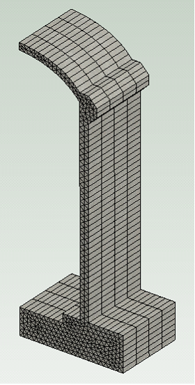
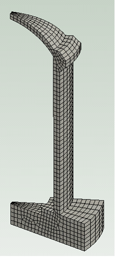
There are various 2D and 3D automatic mesh generators available in CivilFEM based on Advancing front, Overlay, and Delaunay Triangulation techniques. Besides this methods, CivilFEM can perform a volume sweeping, an existing unmeshed volume can be filled with elements by sweeping (by extrusion or revolution) the mesh from a source surface throughout the volume.
Advancing front mesher
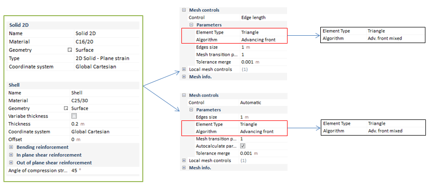
This 2D mesher creates either triangular, quadrilateral, or mixed triangular and quadrilateral mesh. For a given outline boundary, it starts by creating the elements along the boundary. The new boundary front is then formed when the layer of elements is created. This front advances inward until the complete region is meshed. Some smoothing technique is used to improve the quality of the elements. In general, this mesher works with any enclosed geometry and for geometry that has holes inside. The element size can be changed gradually from the boundary to the interior allowing smaller elements near the boundary with no tying constraints necessary.
In addition, mixed triangular and quad elements can be generated using the Advancing Front technique.
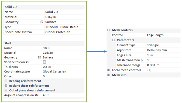
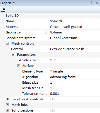
This mesh option would be available in the Edge Length and in the Automatic Mesh Control, in case we are carrying out a Shell, Solid 2D or even in a Solid 3D in an extruded surface mesh control .
Mesh controls we are going to found when defining the parameter mesh on a model, will be explained ahead:
|
Element Type
|
Tetrahedrons/Quadrangle.
|
|
Algorithm
|
Algorithm in order to mesh with.
|
|
Edges Size
|
Maximum element size, the finer the smaller.
|
|
Mesh transition
|
Define a parameter related with the transition of the mesh.
|
|
Autocalculated parameter
|
Mesher calculates automatically the parameter for the mesh transition. This option would be only available in the Automatic Mesh control.
|
|
Tolerance merge
|
When fixing this tolerance, it is pretended to improve the mesh quality.
|
Overlay meshing
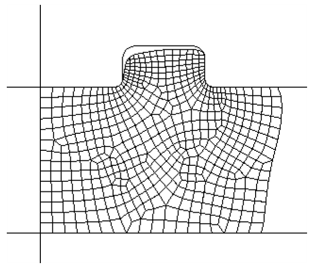
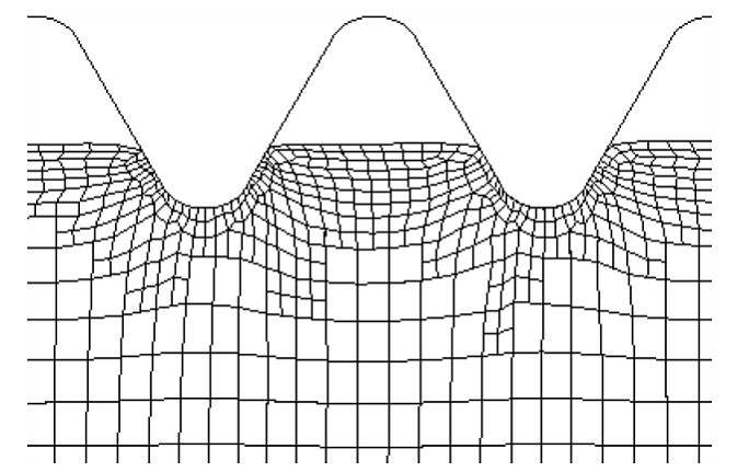
This is a quadrilateral mesh generator. The 2-D overlay mesher is included within CivilFEM. It creates a quadrilateral mesh by forming a regular grid covering the center area of a body. A projection is then used to project all boundary nodes onto the real surface and form the outer layer elements. For the surface that is not in contact with other bodies, a cubic spline line is used to make the outline points smoother. This mesher also allows up to two level refinements on boundary where finer edges are needed to capture the geometry detail, and one level of coarsening in the interior where small elements are not necessary. This refinement and coarsening are performed using the tying constraints.
In general, overlay meshing produces good quality elements. However, it does not take geometry with holes inside. It may not create a good mesh with geometry that has a very thin region or very irregular shape. Also, because the regular grid is created based on the global coordinate system, it may create a poor mesh if the geometry is not aligned with the global coordinate system.
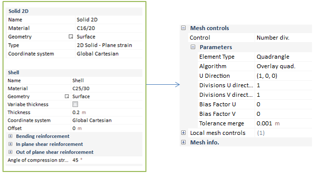
This mesh option would be available in the Number of divisions Mesh Control, in case we are carrying out a Shell or Solid 2D .
Mesh controls we are going to found when defining the parameter mesh on a model, will be explained ahead:
|
Element Type
|
Quadrangle.
|
|
Algorithm
|
Algorithm in order to mesh with. Only the Overlay quad will be active.
|
|
U direction
|
Defines the main direction the mesher is going to take as a principal.
|
|
Divisions U direction
|
Divisions to apply on the U direction, defined as principal.
|
|
Divisions V direction
|
Divisions to apply on the V direction, which is perpendicular to the U direction.
|
|
Bias factor U
|
Parameter for the mesh transition on the U direction.
|
|
Bias factor V
|
Parameter for the mesh transition on the V direction.
|
|
Mesh transition
|
Define a parameter related with the transition of the mesh.
|
|
|
|
|
Tolerance merge
|
When fixing this tolerance, it is pretended to improve the mesh quality.
|
Delaunay Triangulation
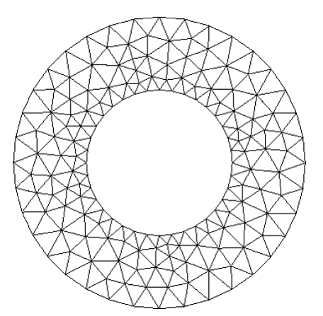
This mesher creates only the triangular mesh. All the triangles satisfy the Delaunay triangulation property. The triangulation is implemented by sequential insertion of new points into the triangulation until all the triangles satisfy the local density and quality requirement.
Delaunay triangulation algorithm assures the triangular mesh created has the best quality possible for the given set of points. The mesher also allows geometry to have holes inside the body and a variation of the elements with different sizes.
This mesh option would be available in the Edge Length and in the Automatic Mesh Control, in case we are carrying out a Shell, Solid 2D or even in a Solid 3D in an extruded surface mesh control .
|
Element Type
|
Tetrahedrons/Quadrangle.
|
|
Algorithm
|
Algorithm in order to mesh with.
|
|
Edges Size
|
Maximum element size, the finer the smaller.
|
|
Mesh transition
|
Define a parameter related with the transition of the mesh.
|
|
Tolerance merge
|
When fixing this tolerance, it is pretended to improve the mesh quality.
|
Volume Mesh By Extrusion/Revolution of a Surface
Mesh generation for volumes (solid structural elements) may be facilitated by expanding a source surface mesh into a solid mesh.
If the source surface mesh consists of quadrilateral elements, the volume is filled with hexahedral elements. If the surface consists of triangles, the volume is filled with wedges. If the surface consists of a combination of quadrilateral and triangular elements, the volume is filled with a combination of hexahedral and wedge elements. The swept mesh is fully associated with the volume.
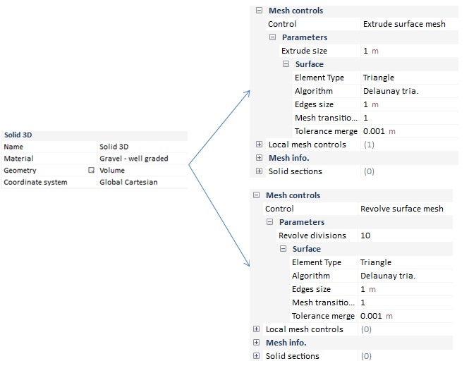
There are two options for mesh control:
-
Extrude Surface Mesh: If the volume was generated by extrusion of a surface this option will be available. The source surface will be meshed as a standard surface with the typical surface mesh options but adding the extrusion size as new control:
-
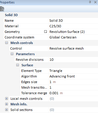
Revolution Surface Mesh: If the volume was generated by revolution of a surface this option will be available. The source surface will be meshed as a standard surface with the typical surface mesh options but adding the number of divisions for the revolution:
Parasolid
In CivilFEM, besides tetrahedral or hexahedral mesh control there is a another option using import/export CAD models.
Only triangle/quadrangle and tetrahedron element types are available. Local mesh controls can be added as happens with other mesh controls. For further information about element types, consult the measuring mesh quality document.
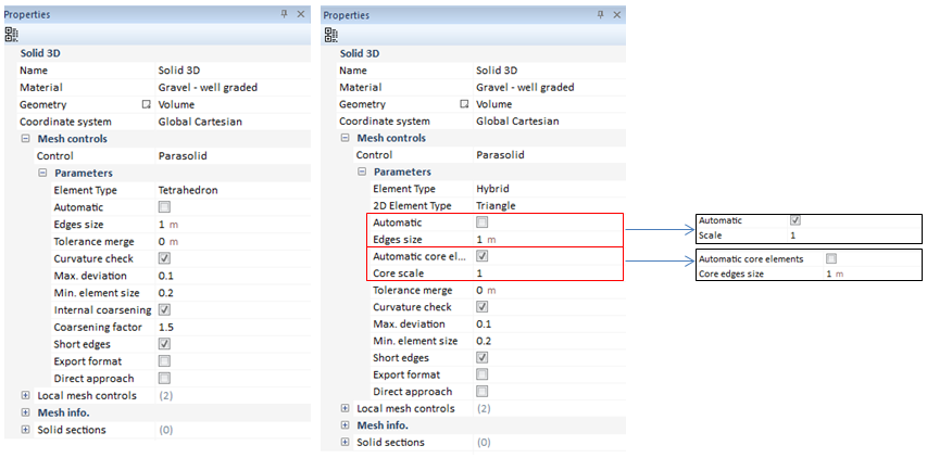
Parasolid option is available both in shells and solids. However, the most complete properties bar, in regard to the whole amount of Parasolid mesh options, is that which belongs to the Solid 3D so, ahead, the visualization of this properties bar will be carried out:
|
Element Type
|
Tetrahedrons/Hybrid.
|
|
2D Element Type
|
This option would be only available in case the Hybrid element type is active. The user may chose between triangle or quadrangle elements.
|
|
Automatic
|
Automatic mesh control calculates automatically the element size. If this option is active, the mesh option Scale will take place instead of the Edges Size option.
|
|
Edges Size
|
Maximum element size, the finer the smaller.
|
|
Scale
|
Applies a specific scale to the automatic size of element.
|
|
Tolerance merge
|
When fixing this tolerance, it is pretended to help the mesh quality.
|
|
Automatic core elements
|
Core elements size is calculated automatically.
|
|
Core scale
|
In case the automatic core elements option is active, core scale option will appear. This option allow the user defining the scale for the automatic size for core elements.
|
|
Core edges size
|
In case the automatic core elements option is deactivated, core edges size option will appear. This option defines the maximum size for the core edges.
|
|
Curvature check
|
This option creates smaller elements in regions of high curvature, in order to better capture the curvature of the surface. Allows control of mesh density at bended surfaces. The Maximum Deviation is the maximum distance allowed between an element edge and the actual surface, relative to length of that edge. Smaller values yield smaller elements in regions of high curvature and a more accurate description of the actual surface of the body.
|
|
Max. deviation
|
This is the maximum distance allowed between an element and the geometry.
|
|
Min deviation
|
Size is defined as a factor relative to the element length.
|
|
Internal coarsening factor
|
This option (for solid bodies only) coarsens the mesh in the interior of the body. This factor can be used to gradually enlarge the tetrahedral element size from the surface to the interior region. It will help reduce the total number of elements in the mesh.
|
|
Coarsening factor
|
Modulating this factor allows creating more elements if necessary.
|
|
Short edges
|
If activating this option, the mesher trys to collapse geometries based on short edges, so as that the mesh execution establishes in the best way possible.
|
|
Export format
|
Activate to change the exported geometry from STEP to IGES format.
|
|
Direct approach
|
Creates parasolid geometry in order to mesh by direct approach.
|
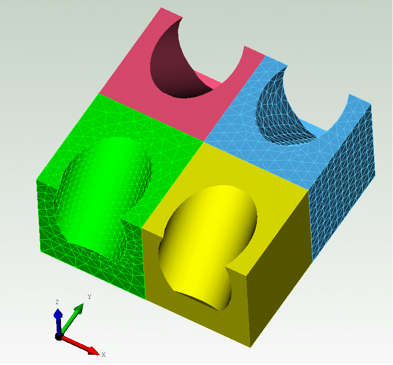
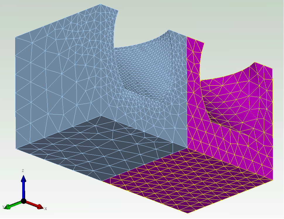
The block on the left shows the finite element mesh obtained with the Curvature Check option switched on. The block on the right shows the mesh obtained with the Curvature Check option switched off.
Clearly, if the Curvature Check option is off, then all bodies are meshed with elements of approximately the same size. The Curvature Check option greatly improves the quality of the mesh for all bodies in the model.
