|
|||||
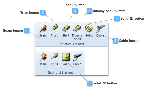
Beam button
Create the structural element for a beam.
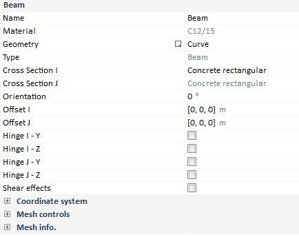
Beam structural elements will contain the following properties:
Material
Only structural and generic materials are allowed to be assigned to linear structural elements, that is, structural/ prestressing steel, concrete or generic material.
Cross section I-J ends
For this version, linear structural elements must have same cross section (constant along the line) for both I-J ends.
Beam offsets
Coordinate values that locate the node with respect to the default origin of the cross section (center of gravity) specified in the section axes system.
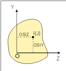
Where:
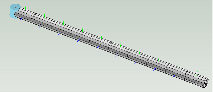
Beam mesh controls
User can take more control in the meshing process by using one of the following element size specifications:
Relation of 20:
Relation of 0.01:
Relation of 20:
Relation of 0.01:
Executing a congruent mesh is one of the most important target in our model, therefore, user must fix properly the mesh to the structural element depending on its dimensions.
Beam hinges
Hinges between beam structural elements can be defined. User must select which of the element local direction (or both) as the revolute axis and in which end (I, J). The possibilities are (mixed configurations are possible):
Shear effects: this option could be activated if the user wants to take into account the transverse shear effects.
If the user would like to know more about the beam finite element, some pieces of information are provided in the Finite element characteristics chapter.
| ||||
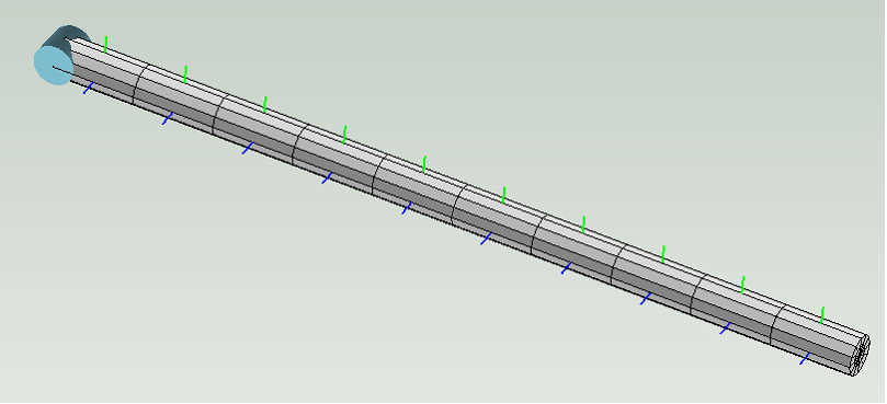
Truss button
Create the structural element for a truss.
Truss elements (tension only or compression-only link elements) will contain the following properties:
Properties bar is showed ahead to be more widely defined:
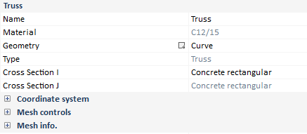
Material
Only structural and generic materials are allowed to be assigned to linear structural elements, that is, structural/ prestressing steel concrete or generic material.
Cross section I-J ends
For this version, linear structural elements must have same cross section (constant along the line) for both I-J ends.
Truss mesh controls
User can take more control in the meshing process by using one of the following element size specifications:
Relation of 20:
Relation of 0.01:
Relation of 20:
Relation of 0.01:
Executing a congruent mesh is one of the most important target in our model, therefore, user must fix properly the mesh to the structural element depending on its dimensions.
If the user would like to know more about the truss finite element, some pieces of information are provided in the Finite element characteristics chapter.
|
Shell button
Create the structural element for a shell.
Shell structural elements will contain the following properties:
Properties bar is showed ahead to be more widely defined:
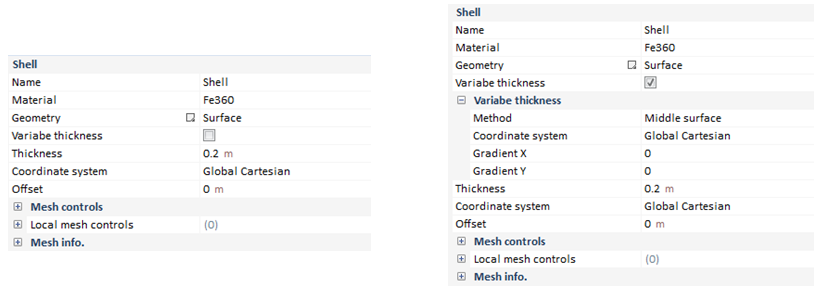
Material
Only structural and generic materials are allowed to be assigned to shell structural elements, that is, structural steel, concrete or generic material.
Thickness
In CivilFEM the shell elements are numerically integrated through the thickness, which can be whether variable or constant through the entire shell structural element.
Shell offsets
Values that locate the node with respect to the default origin of the section (midplane).
Shell mesh controls
User can take more control in the meshing process by using one of the following element size specifications:
A more extended description about the Mesh algorithm will be provided in the corresponding chapter. In addition the Measuring mesh quality has its own headland, in which some aspects about the shape of the elements will be properly cleared.
Executing a congruent mesh is one of the most important target in our model, therefore, user must fix properly the mesh to the structural element depending on its dimensions.
Coordinate system
By default, the shell structural element orientation uses the projection of the global cartesian coordinate system.
Shell reinforcement
Reinforcement in shells shall be defined in many ways:
Bending reinforcement
The following diagram shows the reinforcement configuration according to X, Y directions:

Data needed to define axial + bending reinforcement are:
In plane shear reinforcement
The following diagram shows the reinforcement configuration according to X, Y directions:
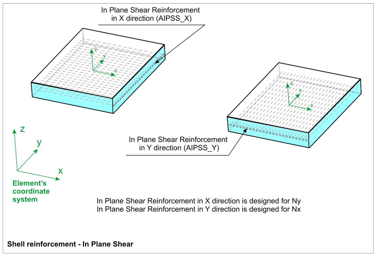
Data needed to define in-plane reinforcement are:
Out of plane shear reinforcement
The following diagram shows the reinforcement configuration according to X, Y directions:
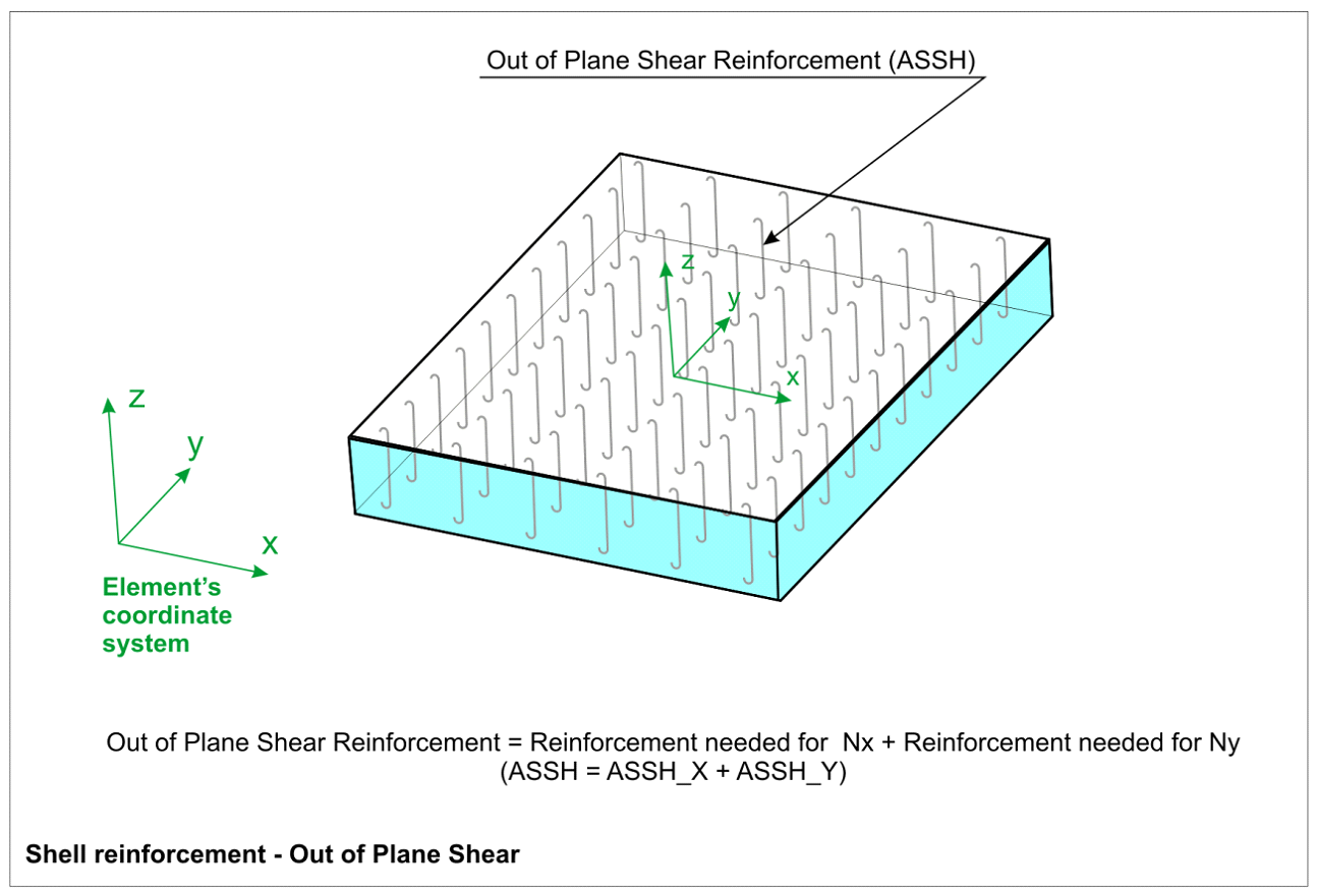
Data needed to define out of plane reinforcement are:
If the user would like to know more about the shell finite element, some pieces of information are provided in the Finite element characteristics chapter.
| ||||||||||||||||||||||||||||||||||||||||||||||||||||
Solid 3D button
Create the structural element for a solid.
Solid 3D structural elements will contain the following properties:
Properties bar is showed ahead to be more widely defined:
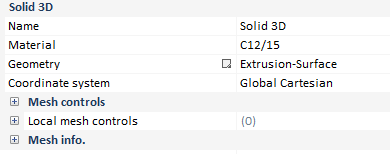
Material
There is no material restriction for solid structural elements, any material can be assigned (including soil and rock materials).
Coordinate system
By default, the solid structural element orientation uses the projection of the global cartesian coordinate system.
Solid mesh controls
User can take more control in the meshing process by using one of the following element size specifications:
A more extended description about the Mesh algorithm will be provided in the corresponding chapter. In addition the Measuring mesh quality has its own headland, in which some aspects about the shape of the elements will be properly cleared.
Executing a congruent mesh is one of the most important target in our model, therefore, user must fix properly the mesh to the structural element depending on its dimensions.
If the user would like to know more about the solid finite element, some pieces of information are provided in the Finite element characteristics chapter.
| ||||||||||
Cable button
Create the structural element for a cable.
Cable structural elements will contain the following properties:
The different finite element types available for solid structural elements are described in the corresponding chapter.
Properties bar is showed ahead to be more widely defined:
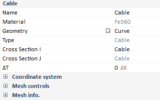
Material
Material is limited to steel, either regular steel, reinforcement steel or prestressing steel. One important consideration is the material law chosen for the steel material. If the default steel behaviour is used, the material will behave with an asymmetric material law (almost no compression resistance and normal tension resistance). If the law is change to plastic behaviour, the actual plastic law will be used. This implies that the compression branch of the material law will be the one defined by the plastic law.
Cross section I-J ends
For this version, linear structural elements must have same cross section (constant along the line) for both I-J ends.
Only cable sections can be used to define a cable structural element.
Temperature prestressing
The cable element used is a non-linear element. Non-linearity implies an approximate solution using a non-exact approach. To help the convergence of the model, the user can define an initial prestressing temperature that will act as an initial tension in the cable.
Cable mesh controls
User can take more control in the meshing process by using one of the following element size specifications:
Executing a congruent mesh is one of the most important target in our model, therefore, user must fix properly the mesh to the structural element depending on its dimensions.
|
Solid 2D button
Create the structural element for a solid.
Solid 2D structural elements will contain the following properties:
Properties bar is showed ahead to be more widely defined:
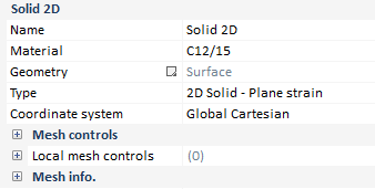
Material
There is no material restriction for solid structural elements, any material can be assigned (including soil and rock materials).
Coordinate system
By default, the solid structural element orientation uses the projection of the global Cartesian coordinate system.
Solid 2D mesh controls
User can take more control in the meshing process by using one of the following element size specifications:
A more extended description about the Mesh algorithm will be provided in the corresponding chapter. In addition the Measuring mesh quality has its own headland, in which some aspects about the shape of the elements will be properly cleared.
Executing a congruent mesh is one of the most important target in our model, therefore, user must fix properly the mesh to the structural element depending on its dimensions.
If the user would like to know more about the solid finite element, some pieces of information are provided in the Finite element characteristics chapter.
| ||||||||||