

Chapter 16
Integration with FLAC3D
16.1 Integration with FLAC3D
16.1.1 Introduction
This feature presents users of CivilFEM and FLAC3D (Fast Lagrangian Analysis of Continuum Modeling in three Dimensions) with a tool that interconnects the two programs.
This connection is established at the preprocessing level, with the possibility of exporting CivilFEM’s model to FLAC3D (~CFFL3D command) and the postprocessing level by importing the structural element forces calculated by FLAC into CivilFEM (command ~FL3DRES). The following figure outlines the integration:
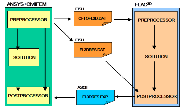
16.1.2 Preprocessing: Exporting the Model
In this step, the model created in CivilFEM is exported to FLAC3D. This operation is performed using the ~CFFL3D command. Only valid selected elements with their attributes are exported.
During the exporting process, the following files are created in the working directory:
CFTOFL3D.DAT FISH file that contains the necessary commands in order to restore the database in FLAC3D. This file may be directly called from FLAC to load the model.
CFTOFL3D.ERR ASCII file, classified in WARNINGS and ERRORS, with possible errors and warnings from the exporting process.
FL3DRES.DAT FISH file to be used in FLAC3D postprocessing. It includes a routine to obtain forces and moments of structural elements.
16.1.2.1 Soil Mesh Generation
The model created by ANSYS and CivilFEM, composed of nodes and elements, is translated into FLAC3D as a finite difference mesh composed by GRIDPOINTS and ZONES.
The SOLID 45 element should be used in ANSYS to model the soil that will be exported to FLAC. This element can be used in any of its degenerated shapes.
If the material associated with the soil elements has been defined in CivilFEM as a soil or rock (with the constitutive model and corresponding properties defined), these properties will also be exported to the FLAC model. On the contrary, if the material has not been defined with CivilFEM, only the geometry of the corresponding zones will be exported; therefore, it will be necessary to introduced them subsequently in FLAC.
In FLAC, the mesh may be refined by introducing the number of divisions the user wishes to obtain from each original element using an argument of the exporting command. This division number is applied to the three element directions in order to maintain the consistency of the mesh.
Another function of the export command is to convert tetrahedral elements into 4 hexahedral elements. This option requires all soil elements modeled in ANSYS and CivilFEM to be tetrahedral. Shell elements lying on the faces of these tetrahedrons will be divided into six triangular elements (2 for each face of the new hexahedrons).
16.1.2.2 Nodes and Structural Elements Generation
The structural nodes and elements selected in ANSYS are extracted as structural nodes and elements in FLAC3D and keep their numbering.
Valid ANSYS elements types for exporting a model to FLAC include:
LINK8, BEAM4, BEAM44, SHELL43, SHELL63
Shells modeled in ANSYS should be 3-node-shells (triangular option) in order to be exported to FLAC.
The FLAC element type exported is defined through CivilFEM material properties associated to the element. Structural elements with a material not defined with CivilFEM will not be exported to FLAC3D.
16.1.2.3 Materials of the Earth Elements
In FLAC3D, exported earth elements are divided into blocks which are labeled MATnnnnn, with ‘nnnnn’ indicating the material number assigned by ANSYS. Therefore, all elements assigned the material number of 12 will be grouped into the MAT00012 block.
Additionally, it is not essential to define the materials in ANSYS, as they can be defined directly in FLAC. It is only necessary to assign the corresponding material number for each element in order to group the materials for their definition in FLAC at a later time.
If the user wishes to define the soil material in CivilFEM, a soil or rock material type must be used, and the constitutive model and its corresponding properties must be defined. If the constitutive model is elastic, its properties will be automatically defined with the corresponding values of the defined rock or soil. If any other constitutive model is used, the user will be required to define these properties.
16.1.2.4 Structural Element Properties
The properties assigned to the structural elements in FLAC3D are taken from the material properties, real constant sets, and element axis systems defined in ANSYS and CivilFEM.
16.1.3 Postprocessing: Importing Results
Once the model has been solved in FLAC3D, structural element results may be sent to CivilFEM in order to postprocess, check and design according to codes.
The structural elements whose results will be imported are the same that were defined initially in CivilFEM (those elements directly defined using ANSYS cannot have their results imported). In the current version, the imported results are limited to the forces and moments of link, beam and shell elements. With shell elements, forces and moments are imported according to the element’s coordinate system. For this reason, elements must be properly aligned when exporting the model.
The importing procedure consists of sending the FLAC3D structural element results to an ASCII file so they can be read by CivilFEM.
As previously stated, when exporting a model from ANSYS and CivilFEM, a FISH file called FL3DRES.DAT is created. This file contains the exporting routine of the structural element results from FLAC. It is only necessary to call this file from FLAC to automatically create the FL3DRES.EXP file with the results.
Once the data are exported from FLAC3D, the results can be automatically imported with the ~FL3DRES command.
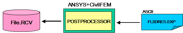
The results will be added as a new ‘Data Set’ into the CivilFEM results file (*.RVC). By applying the exporting command repeatedly, it is possible to create different ‘Data Sets’ that correspond to the each hypothesis solved in FLAC3D.
The results calculated directly in ANSYS and CivilFEM and the results imported from FLAC can coexist in the same results file.
In order to point to the exported results, the normal procedure is followed by using the ~CFSET command.
16.2 Decomposition of a Tetrahedral Mesh into Hexahedral Elements
16.2.1 Introduction
With this utility, all mesh elements that have been degenerated to tetrahedral of SOLID45 elements will be converted to hexahedral elements by breaking down each tetrahedron into four hexahedrons.
If SHELL43 and SHELL63 elements are attached to the faces of the tetrahedrons, these will break down into six triangular elements.
When performing the decomposition, it is necessary to take into consideration the numbering system of the nodes used by ANSYS for the degenerated elements (SOLID 45, SHELL43 and SHELL63) from the group of load states utilized. The numbering system is as follows:
TETRAHEDRON : I, J, K, K, M, M, M, M
SHELLS : I, J, K, K

16.2.2 Nodes Generation
The following nodes are generated:
I,JKM - At center of the tetrahedron
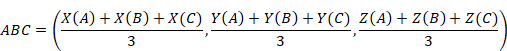
IJM, JKM, KIM, IJK - At center of face
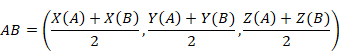
IJ, JK, KI, IM, JM, KM - At center of edge
With the following formulation:
- Edge Nodes
- Center of face Nodes
- Central node

For all the cases: A, B, C, D, Î {I, J, K, L}
16.2.3 Generation of SOLID45 Elements
Once all the nodes are obtained, the new elements are:
ELI = KI, I, IJ, IJK, KIM, IM, IJM, IJKM
ELJ = IJ, J, JK, IJK, IJM, JM, JKM, IJKM
ELK = JK, K KI, IJK, JKM, KM, KIM, IJKM
ELM = KM, M, IM, IKM, JKM, JM, IJM, IJKM
16.2.4 Generation of SHELL43 and SHELL63 Elements
For any element I, J, K, K, this will result in six new elements.
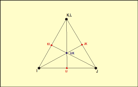
I, IJ, IJK, IJK
IJ, J, IJK, IJK
J, JK, IJK, IJK
JK, K, IJK, IJK
K, KI, IJK, IJK
KI, I, IJK, IJK
16.2.5 Element’s Shape
If the original mesh is formed by regular tetrahedrons, both bricks and generated shells will fulfill the shape limitations established by ANSYS without any difficulties (these shape limitations may differ from those set by FLAC3D due to different calculation procedures, at least when referring to soils.)
However, this will not apply for extremely irregular meshes; therefore, it will be necessary to perform a check of the element shapes using ANSYS features.