

Bridge Sections Explorer
In the sections window there is a list with the sections already created.
Slab bridge sections can be created by using the Slab button (~BRSSLAB command) and Box bridge sections can be created with the Box button (~BRSBOX command).
The title Edit contains the following functions: Modify (~BRSMDF command), Delete (~BRSDEL command), Copy (~BRSGEN command), or List the existing sections (~BRSLST command).
Clicking the button To cross section, it is possble to export a bridge section to a Cross Section (~BRSTOCS command).

General Utilities
It is possible to open an utilities menu, by right clicking on the graphic screen.

- Print: Prints the current view.
- Save As…: Saves the current view as a Windows Bitmap file (BMP).
- Zoom In: A zoom of the section is done. The center of the image is the point where the right click was done.
- Zoom Out: A zoom out of the section will be done.
- Zoom Box: A box can be created by clicking the two corners of it on the screen. A zoom will be done to this box.
- Fit: The initial view of the section is displayed, showing the complete extents of it.
- Move: The graphics shown in the window can be panned with this utility.
- Distance: The distance between two points is calculated by clicking on the desired two points of the screen. The result will be shown on the lower bar of the window. An automatic snap will be done to the characteristic points of the section.
- Angle: The angle between two segments is calculated by clicking on the three points of the screen which define the segments. The result will be shown on the lower bar of the window. An automatic snap will be done to the characteristic points of the section.
Slab Section Creation
In this screen, slab sections may be created by dimensions. To do so, the type of section must be selected (Shape). Possible section types are:
- RS – Rectangular section.
- TS – Trapezoidal section.
- TF – Trapezoidal section with flanges.
- PS – Symmetric polygonal section.
- PA – Asymmetric polygonal section.
After defining the section type, the desired values must be introduced in the corresponding boxes. To identify the notation used in the section’s geometry, the user may consult the figure attached in the bottom left corner of the screen.

Box Section Creation
In this screen, box sections may be created by dimensions. The initial shape is defined here, and must be modified latter on (see Modification of Sections) to create a more complex shape.
After defining the section type, the desired values must be introduced in the corresponding boxes. To identify the notation used in the section’s geometry, the user may consult the figure attached in the bottom left corner of the screen.

Modification of Sections
It is possible to modify an existing section. To do so, the user must select the Bridge Sections Explorer and press the Modify button.

The different possibilities of section modifications are explained hereafter.
Select Menu
For slab sections the following menu is displayed:

In this menu, subgroups of the selected data can be chosen.
CivilFEM will provide the user with the possible section’s alternatives from which to choose:
- Points
- Holes
- Vertical Divisions
In this version of CivilFEM, nothing can be selected for a Box section.
Edit Menu
Slab section: 
Box section: 
In this menu the user may access the section’s properties edition. The menu has the following options:
§ Divisions. Only for Slab sections. The section’s vertical divisions can be moved (~BRMVDL command).
Once a division has been selected, the following icon appears on the upper right corner of the window:
![]()
Clicking on this icon, the dialog to modify the vertical divisions will appear.

The location of the division on the Z axis can be changed in the ZDISP box.
A support can be placed under the vertical division in this section by checkin the Support box (~BRBC command).
§ Dimensions. Only for Box sections. A complex geometry for the box section can be generated here. By entering each of the different menus defined by the buttons on the tool bar, all the different geometrical properties of the section can be changed (dimensions, slopes, bank, etc.)
![]()
§ Mesh Divisions. If the model which will be created is a constant section bridge (see ~BRGEN command) this is the mesh that will be exported to the model (~BRSDIV command). The Cross Sections tesselas will have the same geometry as the mesh shown here. The different parameters of the mesh can be changed using the buttons that appear on the upper bar.
Slab
section: ![]()
Box
section: ![]()
§ Holes. Only for Slab sections. CivilFEM allows to create new holes (~BRHL command), modify existing holes (~BRHLMDF command) or delete previously created ones (~BRHLDEL command).
![]()
When the New hole button is pressed, the following dialog appears.
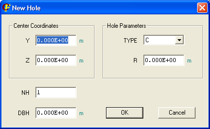
The type of hole can be:
· C – Circular. The radius (R) must be specified.
A series of holes can be created at the same time, by selecting more than one hole (NH – number of holes) and the distance between holes (DBH).
The Modif hole or Delete hole buttons are activated when a hole is selected. In the first case, a dialog similar to the one described above will appear.
View Menu
Box section: 
Slab section: 
In this menu, the user may select the section visualization options.
§ Options. The user may select how to display the elements (points, divisions and holes): numbering, colours and border lines.

§ Elements to represent (Points, Holes, Divisions, Boundary and Mesh Pattern)
Related commands: