

Predesigned Trusses
CivilFEM provides a catalog which can be used to create truss structures. As it will be seen in the present document, trusses can be combined in groups to create complex structures.
There are two groups of structures:
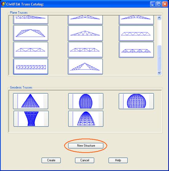
Any of them is created from the initial window, by just clicking on the desired picture:

Note: The desired materials and cross sections that will be used in the structure definition must be created before starting entering any data for the truss.
Plane Trusses
There are 20 different types of plane trusses, which can be defined straight or curved. The first step is to define the straight truss and afterwards it will be curved if needed.

Each one is defined through its geometrical parameters, which are entered in the window shown when the truss is selected. The truss will be placed in the current model at the location defined by the X, Y and Z coordinates on the desired coordinate system (CSYS).
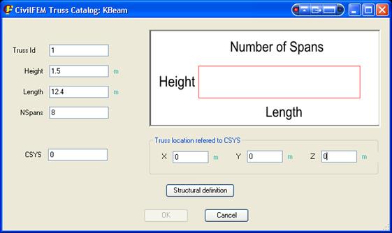
The geometrical parameters for each truss type are shown in the following figure:

The Structural definition button leads to a new dialog in which the properties for each of the groups of beams must be defined.

These properties are:
- Structure Type: Rigid frame or articulated. It is a global property for the whole truss structure.
- Cross section: Each of the groups of bars defined for the truss structure may have a different cross section assigned to it. The cross section must be previously defined. When clicking on the corresponding box to set the cross section, the sketch of the truss structure will show in a different color the group that is being modified.
- Axis direction: The cross section must have a specific orientation if the type of structure is a Rigid Frame.

Piles and Strips (section and orientation) will only be taken into account if a complex structure (nave) is created.
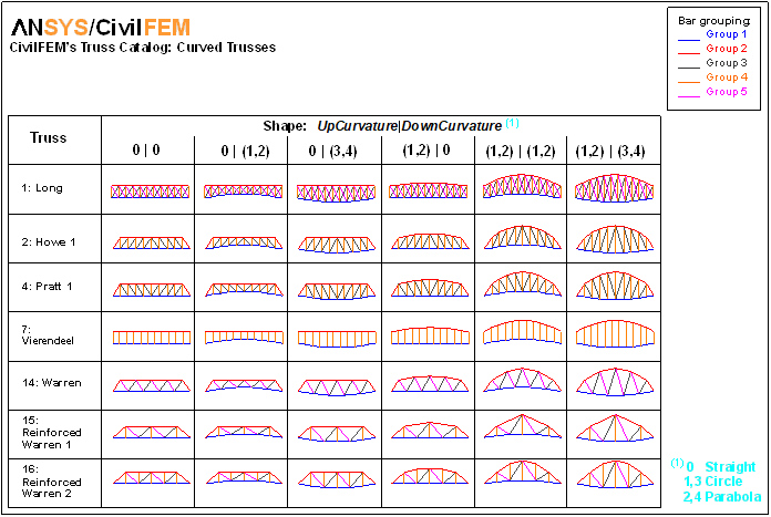
To define a curved truss, if available for the selected typology, the Curved Truss checkbox must be checked.

The upper and/or lower base of the truss can be set as curved by choosing circumference or parabola. In either case, the upper or/and lower arch heights must be set.
Once the truss topology has been defined, the structure can be created:
- Clicking the New Structure button of the main window, a more complex structure is defined using as a starting point the created truss.
- Clicking the Create button, just the defined truss will be created.
The New structure button will open the following dialog, in which the properties to define a nave can be set:

These properties are:
- PileLth: Length of the piles (height of the columns).
- NTrussExtr: Number of trusses.
- TrussDist: Distancia between trusses, each value separated by a coma (“,”).
- NNaves: Number of naves.
- TrussPosition: Orientation of the strips.

The Create button will create the structure in the pre-processor. This structure can then be modified, loaded, solved, etc.
The following figures show several examples of generated structures.


Geodesic Trusses


Clicking on the button of the desired geodesic structure on the main window, the definition dialog for the structure will be shown:
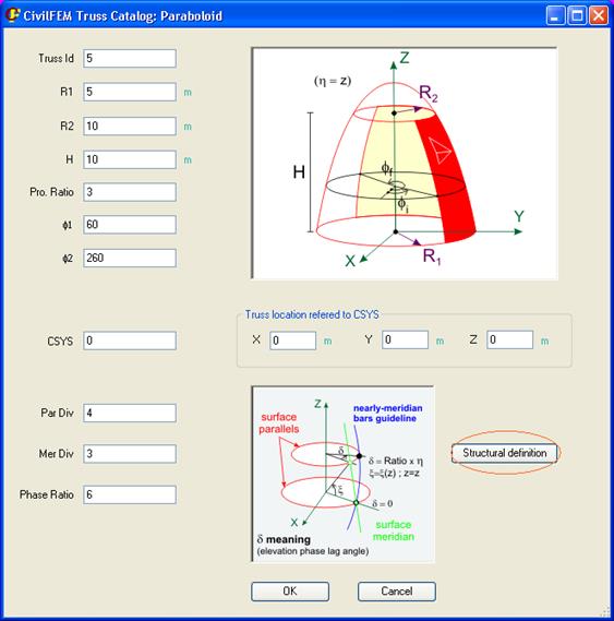
In this window, the general geometric parameters are defined (each structure will need certain parameters, not all of them):
- Truss Id: Truss identification number.
- R: Sphere radius.
- R1: Lower base radius.
- R2: Upper base radius.
- H: Height.
- Zu: Upper base height.
- Zd: Lower base height.
- a, b, c: Length of the semiaxis of the quadric surface.
- Pro Ratio: Geometrical progression ratio in height division.
- f1, f2: Minimum and maximum plan view angle (from 0º to 360º).
- x1, x2: Maximum and minimum elevation angle (from 0º to 360º).
- CSYS: Coordinate system to which the structure will be referred.
- X, Y, Z: Location of the structure, referred to the CSYS.
- Par Div: Number of divisions in the parallels.
- Mer Div: Number of divisions in the meridians.
- Phase Ratio: Phase lag ratio (phase ratio is defined as d in the bellow picture of the window).

The Structural definition button leads to the next window, in which the structural properties are defined:

These properties are:
- Structure Type: Rigid frame or articulated. It is a global property for the whole truss structure.
- Section: Each of the groups in which the truss structure is defined may have a different cross section assigned to it. The cross section must be previously defined. When clicking on the corresponding box to set the cross section, the sketch of the truss structure will show in a different color the group that is being modified.
- Axis direction: The cross section must have a specific orientation if the type of structure is a Rigid Frame.

- Mono Layer/Twin Layer: The structure may be defined as a single layer of beams or as two parallel layers, joined by link beams.

- Link Sec: Cross section number for the linking beams (for twin layer structures).
- Link Axis Direction: Orientation for the linking beams (for twin layer structures).
- LayDist: Distance between the two layers (for twin layer structures).

- Layer type: This combo box defines the connection shapes of meridians and parallels. Just one beam in one or other direction (Clockwise, anticlockwise) or two beams (St. Andrew’s Cross).


Once all the parameters are defined, the windows can be closed by clicking on the OK buttons. The geodesic structure will be created by pressing the Create button in the main window.
The following figures show several examples of generated structures.


