17-C.1 Tunnels
17-C.1.1 Introduction
CivilFEM provides the user with two utilities for tunnel design. These utilities create a finite element model that accurately represents the different stages of the tunnel construction.
17-C.1.2 3D Tunnels Generation
17-C.1.2.1 General Overview
Structural Items
For the construction of the tunnel, apart from the initial terrain that will be excavated, the final structure may be made up of the following parts or structural items:
|
STRUCTURAL ITEM |
3D ELEMENT |
|
Terrain |
SOLID45 |
|
Shotcrete |
SOLID45 |
|
Concrete |
SOLID45 |
|
Steel Trusses |
BEAM188 |
|
Shells |
SHELL63 |
Base Section
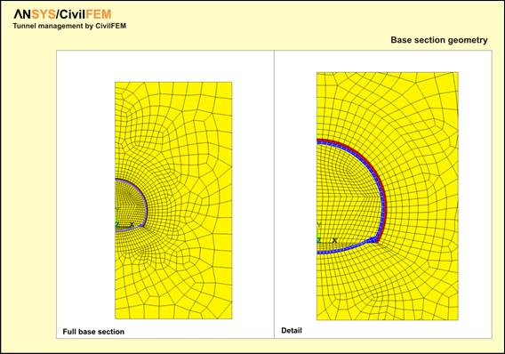
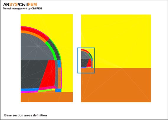
It is referred as base section an Assembly that contains all the objects which make up the generic section of the tunnel, already meshed, in the active coordinate system (CSYS). This base section must be planar and its objects are:
· Keypoints
· Lines
· Areas
· Nudes
· Elements
The assembly may be composed by the following element types:
|
STRUCTURAL ITEM |
2D ELEMENT |
|
Terrain |
SOLID 2D (PLANE42) |
|
Projected concrete |
SOLID 2D (PLANE42) |
|
Concrete |
SOLID 2D (PLANE42) |
|
Metallic trusses |
BEAM 2D (BEAM188) |
|
Shells |
BEAM 2D (MESH 200) |
CivilFEM recognizes the structural item type from the element type used for its mesh.
The base section will be moved to the initial 3D point of the tunnel, and placed perpendicular to the path of it so that the initial point of the path coincides with the coordinate’s origin of the section.
The base section will contain the complete evolution of the tunnel, this is to say, it must include all the parts that make up the tunnel from the beginning of its construction to the end.
Layout of the tunnel
Layout of the tunnel is called to the group of consecutive lines that make up the spatial trajectory which the axis origin of the base section follows in the process of building the model.
To define the layout of the tunnel CivilFEM follows the procedure, generalized for this type of structures, of considering separately the plan and elevation curves:
· The plan layout is made of a succession of straight lines, circumference arcs and clothoid arcs.
· The elevation layout is created as a succession of straight lines and parabolic arcs.
The present version of the tunnel generation tool does not include the possibility of having a layout curved in plan and elevation simultaneously.
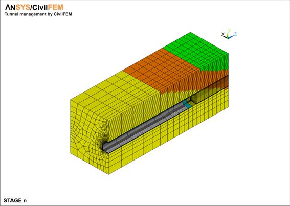
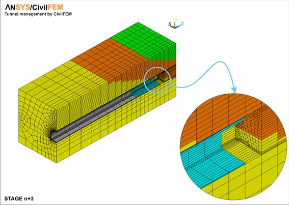
Evolutive process
In order to define the way in which the excavation is really done, CivilFEM uses the following nomenclature:
- Phase Each of the situations the base section goes through, since the excavation starts in the section until it is completely finished and lined.
- Advance Each of the locations the tunnel goes through.
- Delay Delay between the execution of a phase, member of a certain advance, and the last phase that is being started in the analysis STEP.
The figures at the end of this chapter illustrate these definitions.
In Advance 0 the tunnel excavation has not started yet and the terrain is subjected to its initial conditions (s¹0 and e=0).
Between the advances 0 and 1 four phases take place:
0.0 – Terrain without excavation, with its initial stresses
0.1 – Excavation
0.2 – Layout of trusses and projected concrete
0.3 – Concrete
The end of phase 0.3 coincides with advance 1. Following, three new phases are done:
1.1 – Excavation
1.2 – Layout of trusses and projected concrete
1.3 – Concrete
to reach phase 2.0, and so on.
The system CivilFEM uses to number advances and phases is the following:
· Advance 0 (cero) corresponds to the terrain before excavation.
· To go from advance 0 to advance 1 it is necessary to complete the following phases
o Phase 0 – Terrain without excavation
o Phase 1 and following: different excavation phases.
· To go from advance n to n+1 (where n>0) phase 0 is needed, since phase 0 of advanced n is the final phase of advance n-1.


17-C.1.2.2 Definition of Phases and Advance
CivilFEM is capable of reproducing, with the desired accuracy, the most complex constructive process, following the advances/phases system explained in the previous chapter.
In order to carry out the modelization, the user must inform about the constructive process that will be followed and this is done by selecting the phases in which the elements created from each are of the base section exist.
In the example seen before, the process would be described as shown in the following table:
|
Area |
0 (1) |
1 |
2 |
3 |
Type (2) |
|
1 |
* |
* |
* |
* |
SOLID42 |
|
2 |
|
|
* |
* |
SOLID42 |
|
3 |
|
|
|
* |
SOLID42 |
|
4 |
* |
|
|
|
MESH200 |
|
Delay |
- |
0 |
1 |
2 |
|
(1) This phase does only exist in Advance 0
(2) Element type used for meshing (informative)
It is important to notice that the existence of delays implies the execution of different (Advance, phase) pairs at the same time. For this, a command is provided to inform about the load step associated to each pair (~TPLST). In the previous case the association would be
|
ADVANCE |
PHASE |
STEP |
|
0 |
0 |
1 |
|
0 |
1 |
2 |
|
0 |
2 |
3 |
|
1 |
1 |
|
|
0 |
3 |
4 |
|
1 |
2 |
|
|
2 |
1 |
|
|
0 |
3 |
5 |
|
1 |
3 |
|
|
2 |
2 |
|
|
3 |
1 |
|
|
0 |
3 |
6 |
|
1 |
3 |
|
|
2 |
3 |
|
|
3 |
2 |
|
|
0 |
3 |
7 |
|
1 |
3 |
|
|
2 |
3 |
|
|
3 |
3 |
Beam elements
This group is made of trusses. The definition of how they appear in each phase is done in the same way: the user must select the phases in which the elements associated to the meshed lines of the base section exist.
In the example, they would be defined as follows:
|
Line |
0 (1) |
1 |
2 |
3 |
Type (2) |
|
10 |
|
|
* |
* |
BEAM3 |
|
20 |
|
* |
* |
* |
LINK1 |
|
21 |
|
* |
* |
* |
LINK1 |
|
22 |
|
* |
* |
* |
LINK1 |
|
23 |
|
* |
* |
* |
LINK1 |
|
24 |
|
* |
* |
* |
LINK1 |
|
25 |
|
* |
* |
* |
LINK1 |
|
26 |
|
* |
* |
* |
LINK1 |
(1) This phase does only exist in Advance 0
(2) Element type used for meshing (informative)
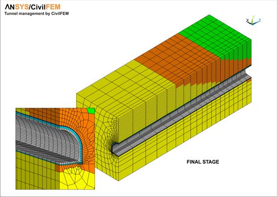
17-C.1.2.3 Examples
The following examples have been created using the CivilFEM 3D Tunnels utility.
The model of the second example has been manually changed, once generated, to simulate the different layers of the terrain.
Example 1
The following table shows the existence of each meshed area and line in every one of the defined phases.
The last row of the table shows the delay the phases have in each advance.
|
|
|
|
|
|
|
|
|
|
|
|
|
|
|
|
|
|
|
|
|
Phase |
|
|
|
|
|
|
|
|
Area |
0 |
1 |
2 |
3 |
4 |
5 |
6 |
7 |
8 |
9 |
|
|
|
1 |
|
|
|
|
|
|
|
|
|
* |
|
|
|
2 |
|
|
* |
* |
* |
* |
* |
* |
* |
* |
|
|
|
3 |
|
|
|
|
|
|
|
|
|
* |
|
|
|
4 |
|
|
|
|
|
|
|
|
|
* |
|
|
|
5 |
|
|
|
|
|
|
|
|
|
* |
|
|
|
6 |
|
|
|
|
|
|
* |
* |
* |
* |
|
|
|
7 |
|
|
|
|
|
|
* |
* |
* |
* |
|
|
|
8 |
|
|
|
|
|
|
|
|
|
* |
|
|
|
9 |
|
|
|
|
|
|
|
|
* |
* |
|
|
|
10 |
|
|
|
|
|
|
|
|
* |
* |
|
|
|
11 |
* |
* |
* |
* |
* |
* |
* |
|
|
|
|
|
|
12 |
* |
* |
* |
* |
* |
* |
* |
|
|
|
|
|
|
13 |
* |
* |
* |
* |
|
|
|
|
|
|
|
|
|
14 |
* |
* |
* |
* |
* |
|
|
|
|
|
|
|
|
15 |
* |
* |
|
|
|
|
|
|
|
|
|
|
|
16 |
* |
* |
* |
* |
* |
* |
* |
* |
* |
* |
|
|
|
17 |
* |
* |
* |
* |
* |
* |
* |
* |
* |
* |
|
|
|
18 |
* |
* |
* |
* |
* |
* |
* |
* |
* |
* |
|
|
|
19 |
* |
* |
* |
* |
* |
* |
* |
* |
* |
* |
|
|
|
Meshed Lines |
|
|
|
|
|
|
|
|
|
|
|
|
|
2 |
|
|
|
|
|
|
|
* |
* |
* |
|
|
|
3 |
|
|
* |
* |
* |
* |
* |
* |
* |
* |
|
|
|
5 |
|
|
|
|
|
|
|
* |
* |
* |
|
|
|
6 |
|
|
|
|
|
|
* |
* |
* |
* |
|
|
|
7 |
|
|
|
|
|
|
* |
* |
* |
* |
|
|
|
8 |
|
|
|
|
|
|
|
* |
* |
* |
|
|
|
Delay |
- |
0 |
0 |
0 |
0 |
1 |
1 |
2 |
2 |
2 |
|
|
|
|
|
|
|
|
|
|
|
|
|
|
|


17-C.1.2.4 Example 2


17-C.1.3 2D Tunnel Generation
The 2D Tunnel Wizard (See CivilFEM Dialog Boxes) allows the user to easily model different types of tunnels and its construction process.
17-C.1.3.1 Structural Items
For the construction of the tunnel, the following components or structural items may be defined in addition to the terrain to be excavated:
|
STRUCTURAL ITEM |
2D ELEMENT TYPE |
|
Terrain |
PLANE182 |
|
Shotcrete |
PLANE182 |
|
Steel Trusses |
BEAM3 |
|
Anchors |
LINK1 |
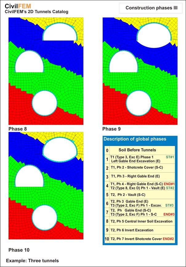
17-C.1.3.2 Construction Process
For 2D models, the number of phases is determined by the type of tunnel geometry (with or without an invert) and the type of construction process.


Tunnel Counter-pressure
During the excavation process of a tunnel, it is necessary to provide lining pressures at the faces of the excavation.
With a 3D model it is not necessary to consider these lining pressures since the model will provide this support. However, a two-dimensional calculation performed without accounting for these pressures would be equivalent to the calculation of a tunnel that had been dug all at once; this would represent an impossible scenario.
In order to account for the effect of the close proximity between excavation faces (which normally is eliminated as the construction phases of the section progress), the user may introduce a confining pressure for each phase.
This equation represents the initial hydrostatic stress before the excavation:
![]()
With gi as the specific weight of the stratus number i and hi as the thickness of this stratus, this sum includes stratum from the point where the stress is measured to the surface directly above this point.
For determining radial pressures, the user may chose to enter the values directly or to have CivilFEM compute the values using the following criteria:
- Uses theory of Panet-Guenot (Convergence-Confinement method).
- Only uses the confining pressures in the first two phases of the tunnel excavation.
PANET-GUENOT Pressures (Convergence-Confinement method)
The theory developed by the program’s authors (also called theory of convergence-confinement) is intended only for circular sections excavated in one phase.
Therefore, the user should be aware of this simplification that the program performs.
The confining pressure is obtained by the following expression:
![]()
(Radial Pressure)
With x as the distance to the face of the excavation, R as the radius of the tunnel (the exterior radius will be (R1 + t1)), and p0 as the terrain initial stress.
CivilFEM uses the value x = 1.0×ForeheadAdvance for the first construction phase and x=2.0×ForeheadAdvance. For any other phase, the value will be zero.
The following table and graphics represent the dimensionless values of spg /p0 for values of x/R.
|
|
|
|
|
|
|
x/R |
Radial Press/p0 |
|
|
|
0.0 |
0.667 |
|
|
|
0.1 |
0.578 |
|
|
|
0.2 |
0.501 |
|
|
|
0.3 |
0.434 |
|
|
|
0.5 |
0.326 |
|
|
|
0.8 |
0.228 |
|
|
|
1.0 |
0.160 |
|
|
|
1.5 |
0.078 |
|
|
|
2.0 |
0.038 |
|
|
|
2.5 |
0.019 |
|
|
|
3.0 |
0.009 |
|
|
|
3.5 |
0.004 |
|
|
|
4.0 |
0.002 |
|
|
|
5.0 |
0.001 |
|
|
|
6.0 |
0.000 |
|
|
|
|
|
|
|
Panet-Guenot Pressure |
|
||

In the calculation, CivilFEM applies a normal pressure to the contour of the tunnel excavated for the current phase.
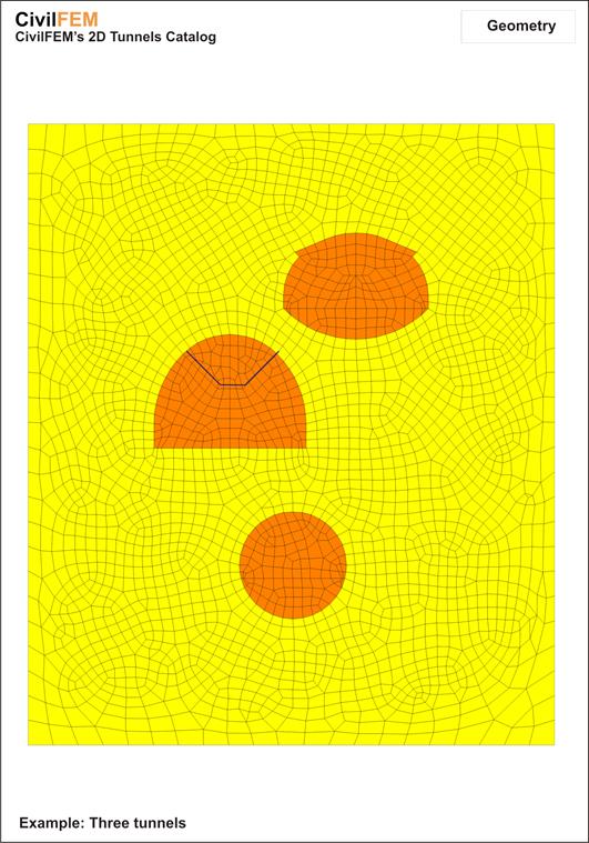
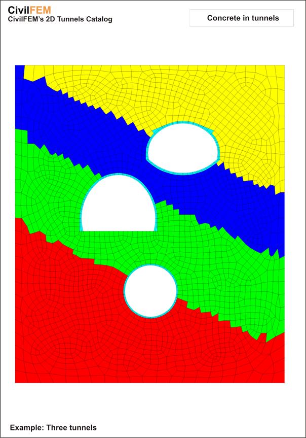
17-C.1.3.3 Example
The following example includes three tunnels within one terrain model, made up of different soil materials and excavated with different construction methods. The model is generated with the CivilFEM 2D Tunnels utility.