

GENERATING PREDESIGNED 2D TUNNELS
This utility assists the engineer in the design of 2D Tunnels and allows the user to create a catalogue of 2D tunnels.
REQUIRED DATA
Before creating the model in the CivilFEM 2D Tunnel Wizard, the following terms must be defined:
- Materials
- The following materials must be defined:
- Concrete.
- Soil or rock for the terrain.
- Structural steel for trusses (If trusses are utilized).
- Reinforcing Steel or Prestressing Steel for anchors. (If anchors are utilized).
- Terrain
- At least one terrain must be defined.
- B&S Properties
- These properties will need to be defined for trusses.
TUNNEL WIZARD
The tunnel wizard allows the user to supplement the required input data with the following tabs:
· Geometry
· Anchors or Trusses
Information about a specific input data can be obtained by placing the cursor over the corresponding input box. However, the user is encouraged to consult the Theory Manual for a more complete comprehension of the input data.
The following screens can be used to enter the required data for design.
TERRAIN:
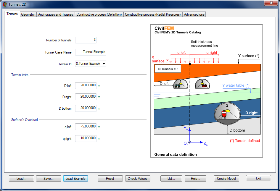
In this tab the user can specify the number of tunnels in the model, the ID of the model corresponding to the 2D tunnel section selected by the user, the terrain limits, and the load on the surface.
The terrain is defined in CivilFEM (command ~TERDEF) and it is necessary to enter the following properties for the calculation:
- Terrain ID
- Surface Height
- Water Table Height
- Surface Load
- Number of Layers, and the Thickness and Material of each Layer
The terrain limits are given by a set of parameters:
- D left: Distance between the left side of the tunnel and the left edge of the terrain with respect to the global axis.
- D right: Distance between the right side of the tunnel and the right edge of the terrain with respect to the global axis.
- D bottom: Distance between the lowest point of the tunnel and the bottom edge of the terrain.
The parameter q left indicates the initial surface load in the x direction, while q right indicates the final surface load such that q left £ q right.
GEOMETRY
In this tab, the user can define the location and the type of each tunnel.
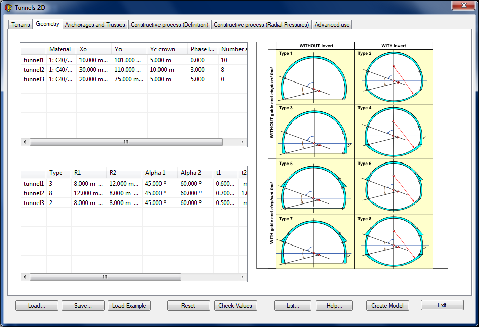
The required input data for each tunnel:
|
Label |
Description |
|
Material |
The material type of concrete |
|
X0 |
X coordinate of the tunnel center |
|
Y0 |
Y coordinate of the tunnel center |
|
Yc crown |
Center Y coordinate, used to create the crown. |
|
Phase lag |
Gap at the beginning of excavation (Measured by the number of phases and refers to the origin of the global structure construction) |
|
Anchorages |
Number of anchors (if applicable) |
|
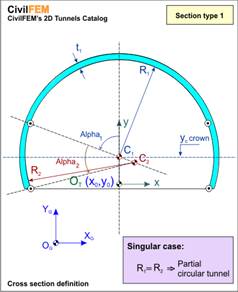
Type |
Geometry type |
|
R1 |
Interior radius of the crown |
|
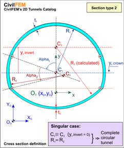
R2 |
Interior radius of the gable zone |
|
Alpha1 |
Central angle of the crown. |
|
Alpha2 |
Central angle of the gable. |
|
t1 |
Crown thickness |
|
t2 |
Elephant foot thickness (if applicable) |
|
t3 |
Invert thickness (if applicable) |
|
Yc invert |
Center Y coordinate, used to create the invert. |
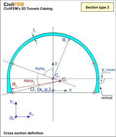
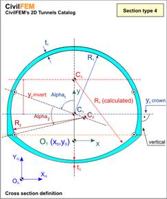
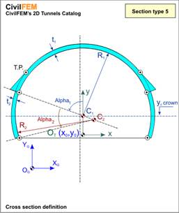
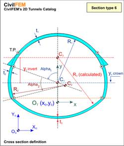
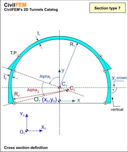
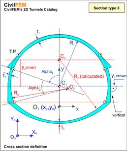
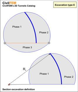
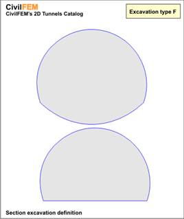
Within the CivilFEM 2D Tunnel Wizard, the user may define tunnels with up to 3 radiuses, with or without an invert, or with or without elephant feet at the union between the crown and the gables. Therefore, up to 8 different types of tunnel models may be defined:
|
TYPE |
DATA DEFINED |
|
|
R1,R2,Alpha1, Alpha2, t1
|
|
|
R1, R2, Alpha1, Alpha2, t1, t3, Yc invert
|
|
|
R1, R2, Alpha1, Alpha2, t1
|
|
|
R1, R2, Alpha1, Alpha2, t1, t3, Yc invert
|
|
|
R1, R2, Alpha1, Alpha2, t1, t2
|
|
|
R1, R2, Alpha1, Alpha2, t1, t2, t3, Yc invert
|
|
|
R1, R2, Alpha1, Alpha2, t1, t2
|
|
|
R1, R2, Alpha1, Alpha2, t1, t2, t3, Yc invert |
ANCHORS OR TRUSSES
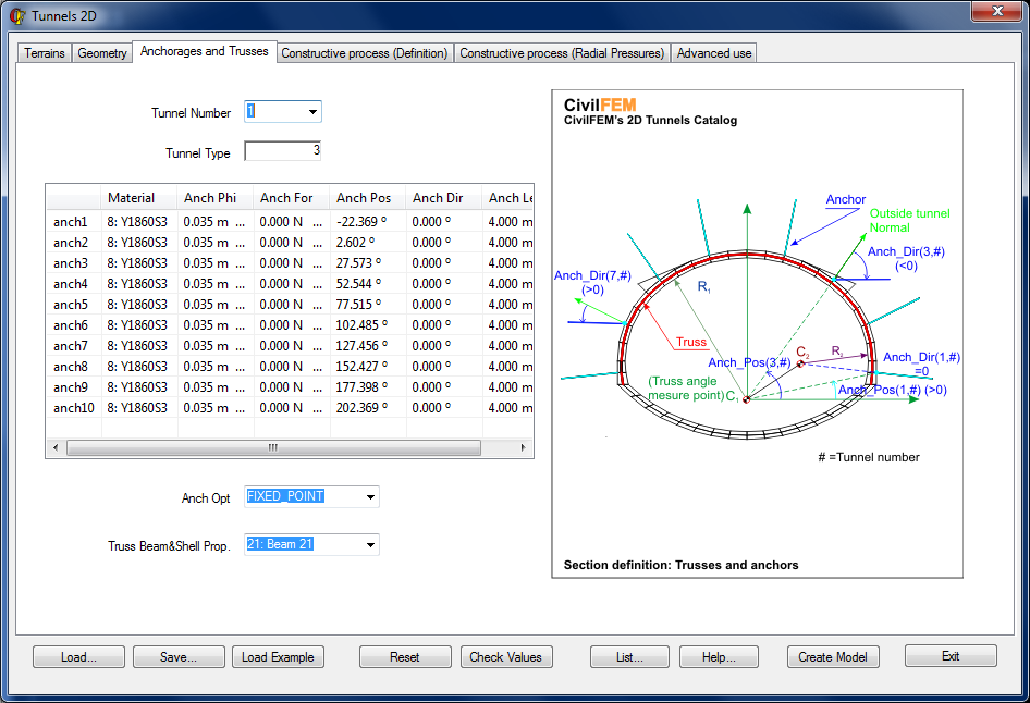
Anchors
Anchors are defined through the angle between the horizontal axis at C1 (at the origin of the crown) and the initial point of the anchor. The direction of the anchor can be defined by specifying the deviation angle from the normal direction. This window will only be available if the number of anchors is greater than zero (Anchorages > 0 in the Geometry Window).
Required data for the definition of anchors:
|
Label |
Description |
||||||
|
Anch Mat |
Anchor Material |
||||||
|
Anch Phi |
Anchor Diameter |
||||||
|
Anch For |
Initial Prestressing Force |
||||||
|
Anch Pos |
Angle between the X axis at C1 and the initial point of the anchor |
||||||
|
Anch Dir |
Direction of anchor with respect to the normal direction. |
||||||
|
Anch Opt |
|
||||||
|
Anch Length |
Anchor Length |
Trusses
The trusses are placed in the center of the shotcrete layer and are associated with a single Beam and Shell Property which can be assigned using the Truss Beam&Shell Prop drop-down menu.
CONSTRUCTIVE PROCESS (DEFINITION)
In this window, the user can identify the tunnel excavation method and define its corresponding parameters.
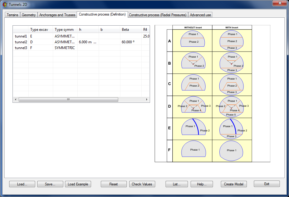
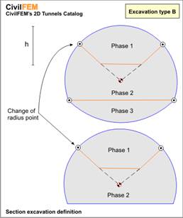
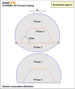
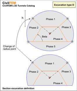
Depending on which type of excavation was selected, the following parameters must be defined:
|
EXCAVATION METHOD |
REQUIRED PARAMETERS |
|
|
None
|
|
|
h
|
|
|
b, Beta
|
|
|
h, Beta
|
|
|
R4, w
|
|
|
None
|
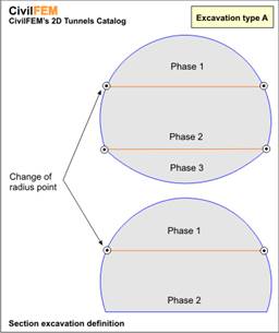
Descriptions of the corresponding parameters:
|
Label |
Description |
|
Type Excav |
Type of construction procedure (A - F) |
|
Type Symm |
The process will be symmetrical or unsymmetrical (Only valid for Type D) |
|
h |
Depth of phase 1 |
|
b |
Width of phase 1 |
|
beta |
Slope angle of phase 1 (Type C) or phase 2 (Type D) |
|
R4 |
Excavation radius of phase 1 (Type E) |
|
w |
Phase 1 excavation thickness (Type E) |
RADIAL PRESSURES
This window contains data that will be necessary to define the lining pressures at the face of the excavation (for more information, consult the chapter 17-C Section 1.3.2 Constructive Process, in the 2D Tunnel section of the Theory Manual).
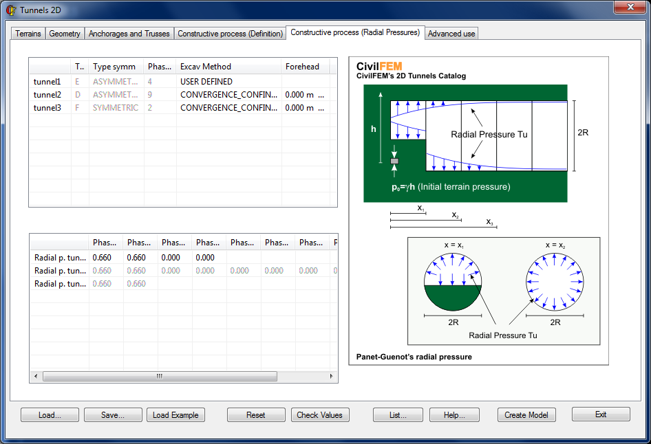
Two different methods can be used to calculate the relationship between the confining pressure and the hydrostatic stress of the soil for each tunnel before the excavation (Excav Method Label):
- CONVERGENCE_CONFINEMENT
- In this case, CivilFEM will calculate the relationship based on PANET-GUENOT
- Only valid for the first two phases.
- Xi values for each phase will be calculated with the Forehead parameter, such that:
- X1 = 1 × Forehead
- X2 = 2 × Forehead
- USER DEFINED
- This option allows the user to directly introduce the values of the factor for each phase (acceptable values are between 0.00 and 1.00)
ADVANCED OPTIONS
This window allows the user to modify the meshing parameters and model convergence options. The user may also save the geometry at particular phases of the calculation.
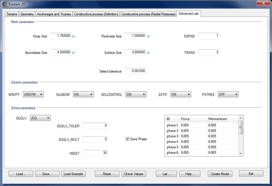
Meshing Parameters
The user can control the refinement of the mesh with the following parameters:
|
Label |
Description |
Default Value |
|
Hoop Size |
Size of the divisions along circumference and on the terrain of the excavation |
1.75 |
|
Thickness Size |
Size of divisions on the tunnel thickness |
1 |
|
Surface Size |
Size of n divisions on the surface |
2 |
|
Boundaries Size |
Size of divisions at the boundaries |
4 |
|
Select tolerance |
Margin of error for the selected boundary conditions |
0.001 |
|
MOPT,TRANS |
Controls the size of the elements at the interior boundary of an area. Will affect the tunnel’s exterior mesh. |
2 |
|
MOPT,EXPND |
Defines the size of internal elements of an area based on the boundary elements of the area. Will affect the tunnel’s exterior mesh. |
1 |
Model Convergence Options
For the majority of cases, the default values are the most appropriate values to attain the best calculation and convergence. However, for more complicated cases, it might be necessary to modify some of these values.
The default values as well as other possibilities are listed in the table below (For every case, it is recommended to consult the Theory Reference for ANSYS and ANSYS Workbench for a greater understanding of these parameters.):
|
Label |
Default Value |
Possible Values |
Description |
|
NROPT |
UNSYM (Contact) FULL (No Contact) |
UNSYM FULL AUTO MODI INIT |
Control options for the Newton-Raphson Method |
|
NLGEOM |
ON |
ON OFF |
Activate / Deactivate Large displacements/strains |
|
SOLCONTROL |
ON |
ON OFF |
Activate / Deactivate options for a set of commands applicable to nonlinear solutions |
|
SSTIF |
ON |
ON OFF |
Activate / Deactivate the effects of the stiffness matrix due to the stress state of the structure through iteration. |
|
PSTRES |
OFF |
ON OFF |
Activate / Deactivate the prestressing actions on the structure |
|
EQSLV |
SPARSE |
FRONT SPARSE JCG ICCG PCG AMG ITER
|
Solver option |
|
EQSLV_TOLER |
0 |
-- |
Tolerance value for every iteration (Only valid for: JCG,ICCG,PCG,AMG) |
|
EQSLV_MULT |
0 |
-- |
Parameter that determines the maximum number of iterations. (EQSLV_MULT × DOF).Only valid for PCG. |
|
NEQIT |
30 |
-- |
Maximum number of equilibrium iterations |
Additionally, the tolerances for each Load Step may be defined through the table within this window.
Geometry of the Phases (Conservation of the Geometry)
The user may choose to save or not to save the geometry of the different phases of the calculation by selecting the checkbox Save Phase.
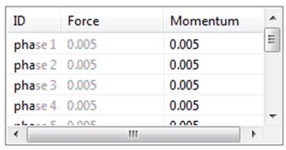
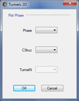
PLOT ELEMENTS
This window allows the user to plot the components created during the modeling process in the 2D Tunnel Wizard.
It is available for preprocessor, solution and postprocessor environments:
|
Label |
Description |
|
PHASE |
Phase number selected |
|
ELEMENTS |
Components created: ALL Terrain Projected Concrete Trusses Anchors Trusses + Anchors
|
|
TUNNEL |
Plot of the tunnels (only applicable if the component is projected concrete) If there are more than one tunnel in the model and the 0 value is chosen, the projected concrete will be selected for all tunnels in the selected phase |
RELATED COMMANDS