

Retaining Walls 1 1/2D
This utility is used to define dimensions, terrain, anchorages, excavation phases, joints and segments for retaining walls.
Geometry 1D
In this tab the retaining walls geometry is defined: dimensions, terrain and segments.
On the top, number of walls can be chosen (it can be one or two walls): Number of Walls, the wall 1 location respect to the origin of coordinates: XLoc, and the possibility to drain the terrain: Drain Excavation.

The data needed are:
· Terrain: indicative ID of the terrain.
· Exc. Side: it can be right or left. It is the wall side that will be excavated for wall number 1.
· Surf Level: terrain higher level. It is filled automatically according to the terrain choice.
· HLength: walls horizontal length.
· Wall Top: walls top level.
· Segment Editor: by clicking on Segment Editor Button the segments that compose the walls can be defined. The data needed are the following:
o ID: segment number. It is filled automatically.
o Wall: wall number, it can be 1 or 2.
o Length: vertical segments length.
o B&S Prop: Beam & Shell Properties. Beams must have constant section.
o El.ID: indicative element type number.

Excavation 1D
In this tab, phases of excavation, anchorages and joints are defined: with Ex Steps Editor, Anchorage Editor and Joint Editor
On the top, number of steps (NSteps) and maximum element size (Size) for the model are defined.

Excavation phases:
- ID: excavation phase number. It is filled automatically.
- N Step: number of the step for calculation. (Several excavation phases can belong to the same step like in the example)
- Wall ID: wall number.
- zExc: excavation level.

Joints:
- ID: joint number.
- N Step: number of the step for calculation in which joints are placed.
- zAnchor #1: wall 1 anchor level.
- zAnchor #2: wall 1 anchor level.
- B&S Prop: Beam&Shell properties.
- El.ID: element type number.

Anchorages:
- ID: joint number.
- N Step: number of the step for calculation in which joints are placed.
- zAnchor #1: wall 1 anchor level.
- zAnchor #2: wall 1 anchor level.
- B&S Prop: Beam&Shell properties.
- El.ID: element type number.

Excavation phase utility 1D
This utility creates a schematic representation of the excavation process defined, before or after the SOLVE. To use it, we must first create the model in Ansys.
If it isn’t, it will ask to open the data file, but it will be not able to solve.


The window is divided into two zones:
On the left are the controls. The buttons are described herein below:

Select the phase you want to view by selecting a number of phases
or view everything by selecting “view all”.

Select items to be displayed: segments, anchors, terrains, walls and joints.

Selecting the minimum and maximum load step to use in the design.
The right side of the window is the display area and has the following pop-up menu when you press the right mouse button:

· Zoom In/Out: Zoom the image.
· Zoom Box: Zoom the selected box.
· Fit: Focuses the image and returns to the original scale.
· Auto-Fit: Automatic fit on redraw.
· Move: Allows moving the image.
· Distance: Calculates the real distance between two points.
· Angle: Calculates the angle between three points.
Retaining Walls 2D
In this window the wall geometry is defined; therefore, this utility defines dimensions, terrain, anchorages, supports, excavation phases and water level.
The commands used for retaining walls 1D window can not be used for 2D, 3D and 3D piles retaining walls windows.
Geometry 2D
In this tab the wall geometry is defined: dimensions, terrain and water level.

Required Data:
Geometrical definition:
- Depth: vertical wall depth.
· XCoord Up: wall X coordinate.
- B&S Pro: Retaining wall Beam&Shell properties.
Beams must have constant section.


Reinforcement Editor:
- Reinforcement Material: Material of the wall’s Reinforcement.
- ASST: area ASST.
- ASSB: area ASSB.
- M.C. Top: top mechanical cover.
- M.C. Bottom: bottom mechanical cover.

Terrain definition:
- LStretch: terrain width on the left wall side.
- RStretch: terrain width on the right wall side.
- Id Terrain: terrain number.
- Wdiff: difference between terrain water level and excavation water level.
- WExcav: water over excavation level.
Initial Stress Definition:
- Initial Str: initial stress. It may be:
· Not Used
· Structural
· Thermal equiv
Excavation 2D
In this tab excavation phases, supports, anchorages and contacts are defined, using Exc. Ph Editor, Support Editor, and Anchorage Editor.


The data needed are the following:
Excavation phases:
- ID: excavation phase number. It is automatically filled.
- Level: excavation level.

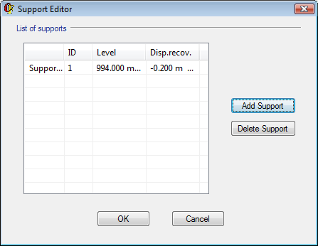
Supports:
- ID: excavation phase number. It is filled automatically.
- Level: support level.
- Disp.recov: displacements recovery when the support is placed.
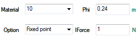
Anchorages:
The following data is needed:
- ID: anchorage number.
- Level: anchorages level.
- Theta: anchorage angle respect to the horizontal line.
- Length: anchorage length.
- Material: anchorage material.
- Phi: anchorage diameter.
- Iforce: initial stress.
- Option:
§ Fixed point.
§ Constrained.
- Nearest point.

Contacts:
It allows the user to include or not contact with separation and friction between the wall and terrain.
The following values have to be filled:
- ContactUp: zone that will not be excavated. If used is chose, it will be considered a friction contact. If not, the unity between wall and terrain will be rigid.
- ContactDown: zone that will be excavated.
- RealConst: contact’s real constant. If its value is 0, CivilFEM defines default real constants.
- Delta: friction angle.

Solution 2D
In this tab meshing parameters and solution control are defined.


Mesh parameters:
- HrzGaps: Gap to consider two horizontal planes coincident.
- H Size: maximum wall division size.
- V Ratio: ratio between the horizontal dimension of the most separated elements of the wall.
- V Size: maximum division size in Oy axis.
- EPS: geometrical selections tolerance.
Advanced Solution parameters:
- NROPT: Newton-Raphson method. (See ANSYS help, command NROPT).
· AUTO: a type is selected automatically.
· FULL: the global system matrix is reformed at each new iteration.
· UNSYM: the same as FULL but supposing that global matrix is not symmetric.
- NLGEOM: activates geometrical non linearity. (See ANSYS help, command NLGEOM).
- SOLCONTROL: specifies whether to use automatic solution controls (see ANSYS help, command SOLCONTROL).
- SSTIF: (see ANSYS help, command SSTIF).
- PSTRES: (see ANSYS help, command PSTRES).
Solver Type:
- EQSLV: solver types. (See ANSYS help, command EQSLV).
- EQSTVLTOL: iterative method tolerance (see ANSYS help, command EQSTVLTOL).
- EQSLVMULT: iterative method tolerance. (See ANSYS help, command EQSLVMULT).
- NEQIT: number of iterations for Newton Raphson method. (See ANSYS help, command NEQIT).
Excavation phase utility 2D
This utility creates a schematic representation of the excavation process defined, before or after the SOLVE. To use it, we must first create the model in Ansys.
If it isn’t, it will ask to open the data file, but it will be not able to solve.

The window is divided into two zones:
On the left are the controls. The buttons are described herein below:
Select the phase you want to view by select a phase number or view everything by selecting “view all”.
Select items to be displayed: segments, anchors, terrains, walls, joints.

Select the items to be displayed: segments, anchors, terrains, walls, joints.
 On click, solve the current model.
The right side of the window is the display area and has the following pop-up menu when you press the right mouse button:
· Zoom In/Out: Zoom the image.
· Box Zoom: Zoom of the selected box.
· Fit: Focuses the image and returns to the original scale.
· Auto-Fit: Automatic fit on redraw.
· Move: Allows moving the image.
· Distance: Calculates the real distance between two points.
· Angle: Calculates the angle between three points.
Retaining Walls 3D
This utility is used to define: dimensions, terrain, anchorages, supports, excavation phases and water level.
The commands used for retaining walls 1D window can not be used for 2D or 3D retaining walls Windows.
Geometry 3D
In this tab the wall geometry is defined, dimensions, terrain and water level. (Shell element must be used for wall.)


![]()


Data needed are:
Geometrical definition:
- Shell Vertex: shell vertex.
- El.ID: element type number.
- Depth: vertical wall length.
- XLeft: wall left point X coordinate.
- YLeft: wall left point Y coordinate.
- Advanced use: if it is not selected, parameters DRUp, DRDown, LeftAngle y RightAngle can not be filled and the wall plan view is being simplified.

Wall Type Editor:
- Continuous: Is entered the desired thickness: thickness.
- Discontinuous: Is entered the following values s, phi.
- Secants: Is entered the following values s, h.
- Alternated: Is entered the following values h, s, y phi.
Reinforcement Editor:
- Reinforcement Material: Material of the wall´s Reinforcement.
- ASSXT: area ASST in the X axis direction.
- ASSXB: area ASSB in the X axis direction.
- ASSYT: area ASST in the Y axis direction.
- ASSYB: area ASSB in the Y axis direction.
- M.Cover: mechanical cover.
- Alpha: Reinforcement angle.
- Theta: Reinforcement angle.

Stretch Editor: to define wall stretches in plan view with lengths and angles:
ID: stretch number. Only in advanced use.
· Length: stretch length.
- Angle: stretch angle with the horizontal line.


Terrain definition:
- ID Terr: terrain number.
- DLup: width of the not excavated terrain at left wall side. (see picture)
- DLDown: width of the excavated terrain at left wall side.
- DRUp: width of the not excavated terrain at right wall side (advanced use only).
- DRDown: width of the excavated terrain at right wall side (advanced use only).
- LeftAngle: angle respect Y axis on the left wall side (advanced use only).
- RightAngle: angle respect Y axis on the right wall side (advanced use only).
- WaterDiff: subtract between terrain water level and excavation water level.
- WaterExca: water over excavation level.

Initial Stress Condition:
 Initial Str: initial stress.
It may be:
Initial Str: initial stress.
It may be:
· Not Used
· Structural
· Thermal equiv
Excavation 3D
In this tab excavation phases, supports, anchorages and contacts are defined, using Exc. Ph Editor, Support Editor, and Anchorage Editor.


Excavation phases:
- ID: excavation phase number. It is filled automatically.
- Level: excavation level.

Contacts:
- ID: excavation phase number. It is filled automatically.
- Level: support level.
- Disp.recov: movement’s recovery when the support is placed. (If it is a negative value, it represents movement before it be placed).
- SuppbyLvl: number of supports by level.

Anchorages:
The following data is needed to define anchorages:
- ID: anchorage number.
- Level: anchorages level.
- Theta: anchorage angle respect to the horizontal line.
- Length: anchorage length.
· AnchBLvl: anchorages number per level.
· LDist: first anchorage distance to the left side of the wall.
· RDist: last anchorage distance to the right side of the wall.
- Material: anchorage material.
- Option:
· Fixed point.
· Constrained.
· Nearest point.
- Phi: anchorage diameter.
· Force: initial stress.


Contacts:
It allows the user to include or not contact with separation and friction between the wall and terrain.
The following values have to be filled:
- ContactUp: zone that will not be excavated. If used is chose, it will be considered a friction contact. If not, the unity between wall and terrain will be rigid.
- ContactDown: zone that will be excavated.
- RealConst: contact’s real constant. If its value is 0, CivilFEM defines default real constants.
- Delta: friction angle.

Solution 3D
This tab defines the meshing parameters and control of the solution. See Solution 2D, for all but the V Ratio parameter.
Excavation phase utility 3D
This utility creates a schematic representation of the excavation process defined, before or after the SOLVE. To use it, we must first create the model in Ansys.
If it isn’t, it will ask to open the data file, but it will be not able to solve.

The window is divided into two zones:
On the left are the controls. The buttons are described herein:
Select the desired phase to be displayed or view the full model by selecting “view all”.

Select the desired views: plan, top, left.
Select the items to be displayed: supports, anchors, terrain, and wall.
On click, solve the
current model.
The right side of the window is the display area, and has the following menu, pop when you press the right mouse button:
· Zoom In/Out: Zoom the image.
· Zoom Box: Zoom the selected box.
· Fit: Focuses the image and returns to the original scale.
· Auto-Fit: Automatic fit on redraw.
· Move: Allows moving the image.
· Distance: Calculates the real distance between two points.
· Angle: Calculates the angle between three points.
Retaining Walls 3D Piles
This utility is used to define, that means, dimensions, terrain, anchorages, supports, excavation phases and water level.
The commands used for retaining walls 1D window can not be used for 2D or 3D retaining walls Windows.
Geometry 3D Piles
In this tab the wall geometry is defined, dimensions, terrain and water level.


The data needed are:
Geometrical definition:
- PilGap: piles gap.
- Depth: vertical wall length.
- Piles B&S Prop: Piles Beam&Shell properties.
- Link B&S Prop: Hoop beam Beam&Shell properties
- PB Diam: piles diameter.
- LB Diam: hoop beam diameter.
- Beam Pos: hoop beam position.
· Rotated 90º
· Not rotated
Advanced use: if it is not selected, parameters DRUp, DRDown, LeftAngle and RightAngle cannot be filled and the wall plan view is being simplified:
Stretch Editor: to define wall stretches in plan view with lengths and angles:
· ID: stretch number. Only in advanced use.
· Length: stretch length.
· Angle: stretch angle with the horizontal line.
REMARK: BEAM188 is used for piles and hoop beam for default.


Plan view:
- XLeft: wall left point X coordinate.
- YLeft: wall left point Y coordinate.
- DLup: width of the not excavated terrain at left wall side. (see picture)
- DLDown: width of the excavated terrain at left wall side.
- DRUp: width of the not excavated terrain at right wall side (advanced use only).
- DRDown: width of the excavated terrain at right wall side (advanced use only).
- LeftAngle: angle respect Y axis on the left wall side (advanced use only).
- RightAngle: angle respect Y axis on the right wall side (advanced use only).
Terrain definition:
- ID Terr: terrain number.
- WaterDiff: subtract between terrain water level and excavation water level.
- WaterExca: water over excavation level
Initial Stress Condition:
- Initial Str: initial stress. It may be:
· Not Used
· Structural
· Thermal equiv
Excavation 3D
In this tab excavation phases, supports, anchorages and contacts are defined, using Exc. Ph Editor, Support Editor, and Anchorage Editor.


Excavation phases:
- ID: excavation phase number. It is filled automatically.
- Level: excavation level.

Supports:
- ID: excavation phase number. It is filled automatically.
- Level: support level.
- Disp.recov: movement’s recovery when the support is placed. (If it is a negative value, it represents movement before it be placed).
- SuppbyLvl: number of supports by level.
- LSupp Dist: distance between the first support and the wall left point.
- RSupp Dist: distance between the last support and the wall right point.

Anchorages:
The following data is needed to define anchorages:
- ID: anchorage number.
- Level: anchorages level.
- Theta: anchorage angle respect to the horizontal line.
- Length: anchorage length.
· AnchBLvl: anchorages number per level.
· LDist: first anchorage distance to the left side of the wall.
· RDist: last anchorage distance to the right side of the wall.
- Material: anchorage material.
- Anc Pos: hoop beam position. (Rotated 90º or not rotated).
- Option:
· Fixed point.
· Constrained.
· Nearest point.
- Disp B&SProp: Beam and Shell Properties.
- Force: initial stress.
- Phi: anchorage diameter.
· PilOffs: Hoop beam offsets.

Contacts:
It allows the user to include or not contact with separation and friction between the wall and terrain.
The following values have to be filled:
- ContactUp: zone that will not be excavated. If used is chose, it will be considered a friction contact. If not, the unity between wall and terrain will be rigid.
- ContactDown: zone that will be excavated.
- RealConst: contact’s real constant. If its value is 0, CivilFEM defines default real constants.
- Delta: friction angle

Solution 3D Piles
This tab defines the meshing parameters and control of the solution. See Solution 2D, for all but the V Ratio parameter.
Excavation phase utility 3D Piles
This utility creates a schematic representation of the excavation process defined, before or after the SOLVE. To use it, we must first create the model in Ansys.
If it isn’t, it will ask to open the data file, but it will be not able to solve.

The window is divided into two zones:
On the left are the controls. The buttons are described herein below:
Select the phase to be displayed or view the full model.
Select the desired view.
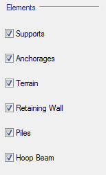
Select items to be displayed: supports, anchors, terrains, walls, piles, hoop beams.
On click, solve the current
model.
The right side of the window is the display area, and has the following pop-up menu when you press the right mouse button:
· Zoom In/Out: Zoom the image.
· Zoom Box: Zoom the selected box.
· Fit: Focuses the image and returns to the original scale.
· Auto-Fit: Automatic fit on redraw.
· Move: Allows moving the image.
· Distance: Calculates the real distance between two points.
· Angle: Calculates the angle between three points.