

13.1 General Concepts
13.1.1 Forces and Moments Sign Criteria
The following figure illustrates the sign criteria for forces and moments. The direction shown in the figure represents the positive direction of the force/moment.

|
Tx |
Axial force in X direction |
|
Ty |
Axial force in Y direction |
|
Txy |
Shear force in XY plane |
|
Mx |
Bending moment on X |
|
My |
Bending moment on Y |
|
Mxy |
Torsional moment XY |
|
Nx |
Shear force in X |
|
Ny |
Shear force in Y |
Note: Mx, My, Mxy, Nx and Ny in CivilFEM are opposite to the SMISC values provided by ANSYS.
13.1.2 Reinforcement Directions
Three type of reinforcements are considered for concrete shells:
· Axial+Bending reinforcement.
· Out of plane shear reinforcement.
· In-plane shear reinforcement.
Note: Some design methods or codes consider in-plane shear together with axial+bending. In these cases, a single group of reinforcement is provided that covers these actions.
The following diagrams show the different reinforcements along with the axis on which they are defined.


13.1.3 Interaction Diagram
The interaction diagram is a curve in space that contains the forces and moments (axial load, bending moment) corresponding to the shell vertex ultimate strength states. In CivilFEM the ultimate strength states are determined through the pivots diagram.

A pivot is a strain limit associated with a material and its position in the shell vertex. If the strain in a section’s pivot exceeds the limit for that pivot, the shell vertex is considered cracked. Thus, pivots establish the positions of the strain plane. So, in an ultimate strength state, the strain plane supports at least one pivot of the shell vertex.
In CivilFEM pivots are defined as material properties and these properties (pivots) are extrapolated to all the points through the thickness of the shell vertex, accounting for the particular material of each point (concrete or reinforcement). Therefore, for the section’s strain plane determination, the following pivots and their corresponding material properties will be considered:
|
A Pivot |
EPSmax. Maximum allowable strain in tension at any point of the shell vertex (the largest value of the maximum strains allowable for each point of the section in case there are different materials in the section). |
|
B Pivot |
EPSmin. Maximum allowable strain in compression at any point of the section (the largest value of the maximum strains allowable for each point of the section). |
|
C Pivot |
EPSint. Maximum allowable strain in compression at the interior points of the section. |
Navier’s hypothesis is assumed for the determination of the strains plane. The strains plane is defined according to the following equation:
![]() EQN.1
EQN.1
where:
|
e (z) |
Strain of a point of the shell vertex. Depends on its z location. |
|
eg |
Strain in the center of the section (center of gravity). |
|
K |
Curvature. |
13.1.3.1 Diagram Construction Process
CivilFEM uses the elements (eg,K) to determine the strains plane (ultimate strength plane) of the shell vertex. The process is composed of the following steps:
1. Values of eg are chosen arbitrarily within the valid range:
![]()
If there is no A pivot, (no reinforcement steel or if the ACI, AS3600 or BS8110 codes are used) there is no tension limit, and this is considered as infinite.
2. Two extreme admissible strains (EPSmin and EPSmax) are defined (different strains for different materials)
3. For each point of the shell vertex, the minimum ultimate strength curvature (K) is calculated.
4. The K curvature adopted will be the minimum of all the curvatures of the shell vertex points, according to the condition K ³ 0.
5. From the obtained K curvature and eg (strain imposed at the center of gravity) the deformation corresponding to each of the shell vertex points e(z), is determined using EQN.1.
6. From the e(z) strain, the stress corresponding to each point of the shell vertex (sp) is calculated. With this method, the stress distribution inside the shell vertex will be determined.
7. The ultimate axial force and bending moment is obtained by integrating the resulting stresses.
Note: For the design process, two components of forces and moments will be calculated: the component relative to the fixed points (corresponding to the concrete) and the component relative to the scalable points (corresponding to the bending reinforcement). The final forces and moments will be equal to the sum of the forces and moments of both components. The forces and moments due to the component for scalable points will be multiplied by the reinforcement factor (w).
![]()
- Steps 1 to 7 are repeated, adjusting the eg value and calculating the corresponding ultimate axial force and bending moment. Therefore, each value of eg represents a point in the interaction diagram of the shell vertex.
13.1.4 Axial + Bending Check and Design
13.1.4.1 Calculation Hypothesis
· The checking procedure only verifies the shell vertex strength requirements; thus, requirements relating to the serviceability conditions, minimum reinforcement amounts or reinforcement distribution for each code and structural type will not be considered.
· It is assumed that plane sections will remain plane. The longitudinal strain of concrete and steel will be proportional to the distance from the neutral axis.
13.1.4.2 Criterion Definition
Checking of elements with regards to axial force and bending moment is performed as follows:
1. Acting forces and moments on the shell vertex (F, M) are obtained from the CivilFEM results file (file .RCV).
2. To construct the interaction diagram of the shell vertex, the ultimate strain state is determined such that the ultimate forces and moments are homothetic to the acting forces and moments with respect to the diagram center.

3. The strength criterion of the shell vertex is defined as the ratio between two distances. As shown above, the distance to the “center” of the diagram (point A of the figure) from the point representing the acting forces and moments (point P of the figure) is labeled as d1 and the distance to the center from the point representing the homothetic ultimate forces and moments (point B) is d2.
![]()
If the criterion is less than 1.00, the forces and moments acting on the shell vertex will be inferior to its ultimate strength, and the shell vertex will be safe. On the contrary, for criterion higher than 1.00, the shell vertex will be considered as not valid.
13.1.4.3 Reinforcement Design
The reinforcement designs produced by the various design methods designed in this chapter will be valid for a criterion value of 1.00 within a tolerance of 1%.
13.2 Design for Bending Moment and Torsion – Wood-Armer Method
13.2.1 Hypothesis of the Calculation
1. The reinforcement design of shells under bending moments is accomplished by the method developed by R.H. Wood and G.S.T. Armer.
2. Once the reinforcement design moments have been calculated, a design for flexure is performed for each shell vertex.
13.2.2 Calculation Process of the Reinforcement Design Moments
Bending moments Mx and My and torsional moments Mxy are calculated from the shell calculation and obtained from the CivilFEM results file. Once these moments are obtained, the program searches for the pair of design moments Mx* and My*. This pair of moments is necessary for the reinforcement design and must include all the possible moments generated by Mx, My and Mxy in every direction.
CivilFEM provides the possibility of placing the reinforcement in two oblique directions: in the X direction of the element or in a direction at an angle a with the element Y direction. This angle a must be defined with shell vertex characteristics using the ~SHLRNF command.

Figure 13.2‑1 Reinforcement Orientations
Design moments for the bottom reinforcement:
![]()
![]()
If either moment is negative, they will be defined as:
1. If ![]()
![]()

2. If ![]()
![]()
![]()
Design moments for the top reinforcement:
![]()
![]()
If either moment is positive, they will be defined as:
3. If ![]()
![]()

4. If ![]()
![]()
![]()
From these design moments, the required top and bottom reinforcement amounts will be calculated with the same procedure as for beams under bending moments.
13.2.3 Bending Design
13.2.3.1 Calculation Hypotheses
·
A rectangular diagram is adopted as the concrete
stress-strain diagram. The diagram is formed by a rectangle with a height y
given by a function of the neutral axis depth x and a width equal to ![]() fcd:
fcd:
![]()

Figure 13.2‑2 Concrete Rectangular Diagram
· The steel reinforcement stress-strain diagram is taken as bilinear with the horizontal plastic branch:
· The center of gravity of the reinforcement will be placed at a point determined by the mechanical cover defined in each shell vertex.
· In the absence of compression reinforcement, the engineering criteria will be taken as the maximum strength of the tensile reinforcement:
![]()
13.2.3.2 Calculation Process
Reinforcement design for flexure follows these steps:
1) Obtaining material strength properties. These properties are obtained from the material properties associated with each shell vertex, which should be previously defined in CivilFEM database, (see ~CFMP command).
2) Obtaining shell vertex geometrical data. Vertex geometrical data must be defined within the CivilFEM database, (~SHLRNF and ~SHLMDF commands).
3) Obtaining reinforcement data. The only data concerning flexure design will be the values for the mechanical cover; these must be defined within the CivilFEM database for the shell vertices (commands ~SHLRNF and ~SHLMDF).
4) Obtaining internal forces and moments.
5) Calculating the limit bending moment. Depending on the active code, the limit bending moment is calculated as follows:
![]()
donde:
|
b |
Width (one unit length). |
||||||
|
d |
Effective depth: d = h – rc |
||||||
|
h |
Shell thickness depth. |
||||||
|
rt |
Mechanical cover for the tension reinforcement. |
||||||
|
rc |
Mechanical cover for the compression reinforcement. |
||||||
|
XLim |
Neutral axis depth for the limit bending moment: |
||||||
|
ecu |
Maximum strain of the extreme compression fiber of the concrete. Depends on the selected code (material EPSmin property). |
||||||
|
esy |
Elongation for the elastic limit: |
||||||
|
|
Coefficient for fcd: |
||||||
|
b |
Compression depth in the concrete rectangular diagram:
|

6) Calculating the required reinforcement. If the design bending moment (Md) is greater than the limit bending moment, both the tension and compression reinforcements will be designed. Otherwise, only the tension reinforcement will be designed.
·
![]()
![]()
From Xn (neutral axis depth), the reinforcements are obtained by:
Tensile
reinforcement: ![]()
Compression
reinforcement: ![]()
·
![]()
Stress in compression reinforcement is given by:
![]()
Therefore, the resultant reinforcement is:
Tensile
reinforcement: ![]()
Compression
reinforcement: ![]()
7) Obtaining design results. Design results are stored in the CivilFEM results file:
ASTX Reinforcement amount at X top.
ASBX Reinforcement amount at X bottom.
ASTY Reinforcement amount at Y top.
ASBY Reinforcement amount at Y bottom.
13.3 Design under Bending Moment and In Plane Loading – CEB-FIP Method
13.3.1 Calculation Hypotheses
1. The reinforcement design of shells under bending moment and in plane loading is accomplished by Model Code CEB-FIP 1990.
2. Reinforcements are defined as an orthogonal net (directions of this net are taken as element X and Y axes).
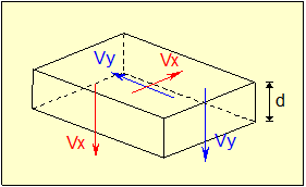
13.3.2 Equivalent Forces and Moments for Reinforcement Calculation
The shell is considered to be divided in three, ideal layers. The outer layers provide resistance to the in-plane effects of both bending and in-plane loading; the inner layer provides for a shear transfer between the outer layers.

Figure 13.3‑1 Three-layer Plate Model
From the forces and moments per unit length (mSdx, mSdy, mSdxy, nSdx, nSdy and vSd) that are calculated from the design and obtained from the CivilFEM results file, the following equivalent forces per unit length are obtained:
![]()
![]()
![]()
Where:
|
zx, zy, zv |
Lever arms between the axial forces in the X and Y directions respectively and the shear forces. |
|
y |
Lever arm between the shear forces (Distance from the mean plane of the slab to the selected force). |
Following the Model Code, CivilFEM adopts the values:
![]()
Where h is the overall thickness of the plate.
So, the former equations change now to:
![]()
![]()
![]()
13.3.3 States and Resistance
These parameters are obtained by:
![]()
![]()
They are also represented in the following figure:

Figure 13.3‑2 Resistance Systems
![]()
![]() Depending
on position of the point (ax, ay), the applicable procedure is as follows (If |vSd| » 0, the program utilizes the sign of nSdx and nSdy,
to place the point in the correct zone). The internal system providing
resistance to in-plane loading may be one of four cases:
Depending
on position of the point (ax, ay), the applicable procedure is as follows (If |vSd| » 0, the program utilizes the sign of nSdx and nSdy,
to place the point in the correct zone). The internal system providing
resistance to in-plane loading may be one of four cases:
CASE I - Tension in reinforcement in two directions and oblique compression in concrete.

CASE II - Tension in reinforcement in Y direction and oblique compression in concrete.

CASE III - Tension in reinforcement in X direction and oblique compression in concrete.

CASE IV - Biaxial compression in the concrete.

According to the case, resistances for the ultimate limit states are the following:
|
Case |
Reinforcements |
Concrete |
|
I |
fytd |
fcd2 |
|
II |
fytd |
fcd2 |
|
III |
fytd |
fcd2 |
|
IV |
fytd |
fcd1 |
Where:
![]() Design tension strength of steel
Design tension strength of steel
![]() (MPa)
(MPa)
![]() (MPa)
(MPa)
13.3.4 Checking Outline
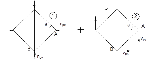
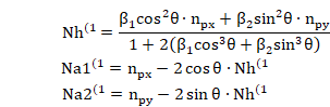
It is assumed that the shell is reinforced with an orthogonal mesh with dimensions of ax and ay.

The angle q is defined between the X-axis and the direction of compression. It can be defined by the user adhering to the condition of 1/3 ³ tan q ³ 3 (By default, q = 45º).
Forces and moments that support a cell of ax x ay dimensions are:
![]()
![]()
![]()
![]()
In general, ![]()

13.3.4.1 CASE I
The method of struts and ties will be applied to the following truss:

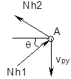
Applying the forces equilibrium in node A:


From the equilibrium of node B, the result is:


To check if these forces and moments are feasible, the strength of the concrete is checked.
Concrete area: ![]()
Stress on
concrete struts: ![]()
This stress is compared to fcd2 to obtain the concrete maximum compression criterion:
![]()
13.3.4.2 CASE II

By equilibrium in node A:

![]()
![]()
![]()
![]()
By equilibrium in node B:

![]()
Maximum compression stress on concrete struts:
![]()
This stress is compared to fcd2 to obtain the concrete maximum compression criterion:
![]()
13.3.4.3 CASE III

By equilibrium in node B:

![]()
![]()
![]()
![]()
By equilibrium in node A:

![]()
The maximum compression stress on concrete struts:
![]()
This stress is compared to fcd2 to obtain the maximum compression of the concrete criterion:
![]()
13.3.4.4 CASE IV- Assuming Reinforcing Steel Bars are Braced
In this situation, the struts and tie model will be the following:

Hyperstatic structure to be separated into two load states.
Both states have simple solutions due to symmetry.
- Solution of Structure 1:
· Node A:

![]()
· Node B:

![]()
· Movements compatibility
Where:
Ah = Concrete strut area
Aa1 = Horizontal steel amount
Aa2 = Vertical steel amount
Eh = Concrete modulus of elasticity
Ea = Steel modulus of elasticity
a = Cell width (ax)
b = Cell depth (ay), (b/a = tan q)
![]()
![]()
The length of the concrete struts before deformation:
![]()
![]()
Differentiating this expression:
![]()
However, Da and Db must coincide with the strain of steel bars:

DL must coincide with the strain of the concrete struts:
![]()
![]()
![]()
From the obtained equations, the following linear system is created:

Which when solved gives:
- Solution of Structure 2:
Due to non-symmetrical loads, the central bars (steel) are not applicable; therefore, equation 2 is determinant, and the following expression is obtained:
![]()
![]()
![]()
Therefore:
![]()
![]()
![]()
Total Actions in Case IV
Adding the actions of 1 and 2:
![]()
![]()
![]()
Where:

With the assumption of braced bars, Na1 and Na2 signs correspond to compression for a + sign and tension for a - sign.
13.3.4.5 Case IV – Assuming Steel Bars are Not Braced
For steel bars without braces, there are two possible determinant truss configurations.
· Case 1

By equilibrium in A node:

![]()
![]()
![]()
![]()
By equilibrium in B node:

![]()
· Case 2

By equilibrium in B node:

![]()
![]()
![]()
![]()
By equilibrium in A node:

· Discussion:
With this situation, CivilFEM will select whichever of the two cases satisfies:
![]() and
and ![]()
If neither case results in appropriate signs, it will be impossible to equilibrate the force and moment states without bracing the steel bars.
The maximum compression stress on the concrete struts is:
![]()
This stress is compared with fcd1 to obtain the concrete maximum compression criterion:
![]()
13.3.4.6 Signs Conventions
For all the cases, the positive sign corresponds with the result shown in the figures.
13.3.4.7 Steel Amounts
For all the cases, steel reinforcement amounts per unit length of the shell are:

13.3.5 Reinforcement Checking in Intermediate Layer
The checking process described in 6.4.2.5 article of Model Code CEB-FIP1990 will be executed.
The principal shear force is:
![]()
Acting on a surface at an angle f, relative to the Y-axis
![]()
The following check is to performed: ![]()
![]()
![]()

Where d is the total depth without the mechanical cover (in mm), and rx, ry are the ratios for the reinforcement closest to the face in tension, in the direction perpendicular to the surface that V1 acts on.
13.3.6 Required Parameters
13.3.6.1 General Requirements
· Material properties described in section 0.
· zx, zy, zv and y parameters which are defined for each element as a fraction of the depth at each point. As previously stated, CivilFEM uses the specifications from section 6.5.4 of the Model Code.
![]()
![]()
· The parameter that indicates whether the bars of the element are braced.
· Angle q between the reinforcement X axis (element X axis) and the direction of compression. By default, q = 45º (although any angle is valid if 1/3 ³ tan q ³ 3).
13.3.6.2 Checking Requirements
Va1 and Va2 reinforcement amounts per unit length of the shell.
13.4 Design according to the Orthogonal Directions Method
13.4.1 Calculation Hypothesis
1. The design of reinforcement for bending moments and axial forces is performed independently for each direction.
1. Reinforcements are defined as an orthogonal mesh (directions of this mesh are taken as element X and Y axes).

13.4.2 Design Forces and Moments
The axial forces (T*x, T*y) and bending moments (M*x, M*y) used for the design are those obtained for the reinforcement directions as follows:
If torsional moment and membrane shear force are neglected:
![]()
![]()
![]()
![]()
If torsional moment (Mxy) and membrane shear force (Txy) are taken into account then two checks are perfomed considering membrane shear as tension and as compression. CivilFEM will select the most unfavorable results (providing the largest reinforcement values):
1)
![]()
![]()
![]()
![]()
2)
![]()
![]()
![]()
![]()
If only torsional moment (Mxy) is considered:
![]()
![]()
![]()
![]()
Where X and Y represent the orthogonal directions of bending reinforcement of the shell.
13.4.3 Maximum Allowable Stress/Strain in Reinforcement
Reinforcement is designed using one of the following conditions:
- The maximum strain allowed in tension is defined for the material (EPSMAX). It will be used as pivot A in the interaction diagram. This condition is typically used for Ultimate Limit States.
- The maximum stress allowed is specified (see ~CHKCON and ~DIMCON commands). This condition is typically used for Serviceability Limit States in order to control cracking.
13.4.4 Check and Design
13.4.4.1 Calculation Process
Reinforcements design for the Orthogonal Directions method follows these steps:
1) Obtaining material strength properties. These properties are obtained from the material properties associated with each shell vertex, which should be previously defined in CivilFEM database, (see ~CFMP command).
2) Obtaining shell vertex geometrical data. Vertex geometrical data must be defined within the CivilFEM database (~SHLRNF and ~SHLMDF commands).
3) Obtaining reinforcement data. The only data associated with the bending moment design are the mechanical cover values for the reinforcement; these must be defined within the CivilFEM database for the shell vertices (~SHLRNF and ~SHLMDF commands).
4) Obtaining internal forces and moments. The acting bending moments and axial forces are those obtained for the X and Y directions of each element (T*x, T*y, M*x, M*y).
5) Check and design. Depending on the active code, the checking or design is performed using the pivot diagram described for the checking and design of concrete cross sections.
For checking, the criteria for axial force and bending moment are obtained as for the pivot diagram for beams for each direction.
All reinforcements are considered as scalable for design. The obtained reinforcement factor is therefore the value that must be used to multiply the upper and lower reinforcement amount to fulfill the code requirements.
6) Checking results. Checking results are stored in the CivilFEM results file:
CRT_X Criterion for X direction.
CRT_Y Criterion for Y direction.
N_X Design axial force for X direction
M_X Design bending moment for X direction.
N_Y Design axial force for Y direction.
M_Y Design bending moment for Y direction.
7) Design results. Design results are stored in the CivilFEM results file:
ASTX Reinforcement amount for X direction, top surface.
ASBX Reinforcement amount for X direction, bottom surface.
ASTY Reinforcement amount for Y direction, top surface.
ASBY Reinforcement amount for Y direction, bottom surface.
DSGCRTX Design criterion for X direction.
DSGCRTY Design criterion for Y direction.
T_X Design axial force for X direction.
M_X Design bending moment for X direction.
T_Y Design axial force for Y direction.
M_Y Design bending moment for Y direction.
13.5 Design according to the Most Unfavorable Direction Method
13.5.1 Introduction
The objective of this design method is to calculate the reinforcement requirement of the concrete shells with a method based on the one proposed by CAPRA-MAURY; this method accounts for bending moments (Mx, My) and torsional moments (Mxy) as well as axial forces (Tx, Ty) and in-plane shear forces (Txy).
The method will calculate a group of top (Axt, Ayt) and bottom (Axb, Ayb) reinforcements which will create equilibrium with the existing forces and moments and with the minimum weight possible, therefore:
Axt + Ayt + Axb + Ayb = Minimum
Reinforcements are considered to be orthogonal and set along the X and Y axes of the element.

13.5.2 Design Forces and Moments
Considering a plane with its normal contained in the shell and located at an angle q from the positive X axis of the element, the bending moment and axial force (M, T) will be:

The shell forces and the orientation of the local element coordinate system shown in the previous figure, are identical to the ANSYS respective figures.
![]()
![]()
From these values, the reinforcements Aqt y Aqb can be determined.
The following conditions must be satisfied:
![]()
![]()
![]()
To solve the problem above, the total bottom reinforcement and the total top reinforcement are minimized separately. For the bottom reinforcement, the calculation method is the following:
|
Minimum of
With the conditions:
|

Note: The shell forces and the orientation of the local element coordinate system showed in the first figure, are identical to the ANSYS respective figures.
13.5.3 Maximum Allowable Stress/Strain in Reinforcement
Reinforcement is designed utilizing one of the following conditions:
- The maximum strain allowed in tension is defined for the material (EPSMAX). This strain will be used as pivot A in the interaction diagram. This condition is typically used for Ultimate Limit States.
- The maximum stress allowed is specified (see ~CHKCON and ~DIMCON commands). This is the condition typically used for Serviceability Limit States in order to control cracking.
13.5.4 Checking and Design
13.5.4.1 Calculation Process
Reinforcements design for the Most Unfavorable Direction method follows these steps:
1) Obtaining material strength properties. These properties are obtained from the material properties associated with each shell vertex, which should be previously defined in CivilFEM database, (see ~CFMP command).
2) Obtaining shell vertex geometrical data. Vertex geometrical data must be defined within the CivilFEM database (~SHLRNF and ~SHLMDF commands).
3) Obtaining reinforcement data. The only data pertaining to bending moment design are the values of the mechanical cover; these values must be defined within the CivilFEM database for the shell vertices (~SHLRNF and ~SHLMDF commands).
4) Obtaining forces and moments. For each direction q, a pair of bending moment – axial force is obtained, as described previously.
5) Check and Design. Depending on the active code, the checking or design is performed using the pivot diagram described for the checking and design of concrete cross sections.
For checking, the same criteria for axial force and bending moment are obtained as for the pivot diagram for beams for each direction.
6) Checking results. Checking results are stored in the CivilFEM results file:
M Bending moment used to evaluate the criterion.
N Axial force used to evaluate the criterion.
CRT_TOT Total criterion.
7) Design results. Design results are stored in the CivilFEM results file:
MT Bending moment used for the design of the top reinforcement.
NT Axial force used for the design of the top reinforcement.
MB Bending moment used for the design of the bottom reinforcement.
NB Axial force used for the design of the bottom reinforcement.
CRT_T Criterion for the top surface.
CRT_B Criterion for the bottom surface.
ASTX Reinforcement area for the X direction, top surface.
ASBX Reinforcement area for the X direction, bottom surface.
ASTY Reinforcement area for the Y direction, top surface.
ASBY Reinforcement area for the Y direction, bottom surface.
DSG_CRT Design total criterion.
13.6 Check and Design for Out-of-Plane Shear Loadings according to Eurocode 2 (ENV 1992-1-1:1991)
13.6.1 Required Input Data
Shear checking or design according to Eurocode 2 requires a series of parameters described below:
1) Materials strength properties. These properties are obtained from the material properties associated with each one of shell vertices and for the active time, (see ~CFMP command). Those material properties should be previously defined. The required data are the following:
fck characteristic compressive strength of concrete.
fyk characteristic yield strength of reinforcement.
gc partial safety factor for concrete.
gs partial safety factor for reinforcement.
2) Shell vertex geometrical data:
th thickness of the shell vertex (~SHLRNF command).
3) Geometrical parameters. Required data are the following:
c bending reinforcement mechanical cover (~SHLRNF command). If different mechanical cover is defined (MCXT, MCXB, MCYT, MCYB), c is the largest mechanical cover among the most tractioned face in each direction
r1 ratio of the tension longitudinal reinforcement per unit length of the shell:
![]()
where:
Ass the area of the tension reinforcement (~SHLRNF command).
q angle of the compressive struts of concrete with the longitudinal axis of member, (parameter THETA of ~SHLRNF command):
0.4 < cotan q < 2.5
4) Shell vertex reinforcement data. Data concerning reinforcements of the shell vertex must be included within CivilFEM database. (See ~SHLSHR command). Required data are the following:
Ass area of reinforcement per unit area, (parameter ASS of ~SHLSHR command).
The reinforcement ratio may also be obtained with the following data:
sx, sy spacing of the stirrups in each direction of the shell, (parameters SX and SY of ~SHLSHR command).
f diameter of bars (parameter PHI of ~SHLSHR command).
nx, ny number of stirrups per unit length in each direction of the shell (parameters NX and NY of ~SHLSHR command).
5) Shell vertex internal forces. The shear force acting on the vertex as well as the concomitant axial force are obtained from the CivilFEM results file (.RCV).
Design shear force (VSd) is obtained from the shear force in the X and Y directions:
![]()
which forms an angle with the Y axis:
![]()
The value defined for the design compression force (TSd) is the maximum of all directions:

Design compression force takes into account axial force in x, y directions and in-plane shear using Mohr’s circle stress transformation equations.
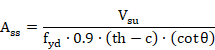
The total shear
reinforcement ![]() is
computed from the reinforcements in the X and Y directions, according to
CEB-FIP Model Code 1990 (article 6.4.2.5.):
is
computed from the reinforcements in the X and Y directions, according to
CEB-FIP Model Code 1990 (article 6.4.2.5.):
![]()
13.6.2 Out-of-Plane Shear Checking
13.6.2.1 Checking Whether the Shell Vertex Will Require Shear Reinforcement
Design shear force VSd is compared to the design shear resistance (VRd1):
![]()
![]()
where:
tRd = basic design shear strength in N/mm2 depending on the concrete strength (fck):
|
fck |
12 |
16 |
20 |
25 |
30 |
35 |
40 |
45 |
50 |
|
tRd |
0.18 |
0.22 |
0.26 |
0.30 |
0.34 |
0.37 |
0.41 |
0.44 |
0.48 |
For other values of fck a linear interpolation is done. For values of fck < 12, an interpolation is done between 0 and 0.18. For values of fck > 50, tRd = 0.48 for every case.
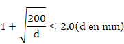
![]() where th and c are expressed in meters
where th and c are expressed in meters
![]() where NSd is the concomitant axial force
(positive for compression).
where NSd is the concomitant axial force
(positive for compression).
If shear reinforcement has not been defined in the shell vertex, a check is made to ensure the design shear force (VSd) is less than the maximum design shear force that does not crush the concrete compressive struts (VRd2):
![]()
![]()
where ![]()
If the shell vertex is subjected to axial compressive force, VRd2 should be reduced in accordance to the equation below:
![]()
Where ![]() is
the effective average stress in the concrete due to axial force.
is
the effective average stress in the concrete due to axial force.
Results are written for each end in the CivilFEM results file:
VRD1 Design shear resistance without considering the reinforcement for each direction.
![]()
CRVRD1 Ratio of the design shear force (VSd) to the resistance VRd1.
![]()
For vertices subjected to a tensile axial force so that VRd1=0, CRVRD1 is assigned a value of 2100.
If shear reinforcement has not been defined, the results below are also given:
VRD2 Maximum design shear force that can be carried by the shell without crushing of the concrete compressive struts. If the shell is subjected to an applied compressive axial force, it will take the reduced value.
![]()
CRVRD2 Ratio of the design shear force (VSd) to the resistance VRd2.
![]()
If the shell vertex is subjected to a compressive axial force so that VRd2,red=0, CRVRD2 will be assigned a value of 2100.
The increase in longitudinal reinforcement due to shear is stored in the ASST and ASSB parameters (for top and bottom surfaces of the shell respectively).
13.6.2.2 Shear Criterion
The shear criterion indicates whether the shell vertex is valid for the design forces (if it is less than 1, the vertex satisfies the code provisions; whereas if it exceeds 1, the vertex will not be valid). Furthermore, it includes information about how close the design force is to the ultimate strength. The shear criterion is defined as follows:
![]()
For each end, this value is stored in the CivilFEM results file as the parameter CRT_TOT.
A value of 2100 for this criterion indicates that VRd2 or VRd3 are equal to zero.
13.6.3 Out-of-Plane Shear Design
13.6.3.1 Checking Whether the Shell Vertex will Require Shear Reinforcement
VSd is compared to the design shear resistance (VRd1):
![]()
![]()
where:
tRd = basic design shear strength in N/mm2 depending on the concrete strength (fck):
|
fck |
12 |
16 |
20 |
25 |
30 |
35 |
40 |
45 |
50 |
|
tRd |
0.18 |
0.22 |
0.26 |
0.30 |
0.34 |
0.37 |
0.41 |
0.44 |
0.48 |
For other values of fck a linear interpolation is done. For values of fck < 12 an interpolation is done between 0 and 0.18. For values of fck > 50, tRd = 0.48 always.
![]() where th and c are in meters.
where th and c are in meters.
![]() where NSd is the concomitant axial force
(positive for compression).
where NSd is the concomitant axial force
(positive for compression).
Results are written for each element end in the CivilFEM results file:
VRD1 Design shear resistance without considering the reinforcement.
![]()
CRVRD1 Ratio of the design shear force (VSd) to the resistance VRd1.
![]()
13.6.3.2 Maximum Shear Force Resisted by the Concrete Compressive Struts
The condition below must be satisfied:
![]()
where ![]()
For a shell vertex subjected to an axial compressive force, VRd2 should be reduced in accordance to the equation below:
![]()
Where ![]() is
the average effective stress in concrete due to the axial force.
is
the average effective stress in concrete due to the axial force.
The following results will be stored:
VRD2 Maximum design shear force resisted by the shell vertex without the crushing of the concrete compressive struts. For vertices subjected to axial compression, the value will be reduced.
![]()
CRVRD2 Ratio of the design shear (VSd) to the resistance VRd2.
![]()
For vertices subjected to axial compression so that VRd2,red=0, CRVRD2 is defined as 2100.
If design shear force is greater than the shear force due to crushing of concrete compressive struts, the reinforcement design will not be feasible; consequently, the reinforcement parameter will be defined as 2100. In this case, the element will be labeled as not designed.
If there is no crushing by oblique compression, the calculating process continues.
13.6.3.3 Contribution of the Required Transverse Reinforcement
The condition of the validity of the shell vertex, concerning shear force is:
![]()
Vcd concrete contribution, equal to VRd1 calculated previously.
Vwd shear reinforcement contribution.
Therefore, the reinforcement contribution must be:
![]()
If the value assigned to the angle of the concrete compressive struts (q) is 45º, the standard method is adopted; otherwise, the variable strut inclination method is used:
|
|
à |
standard method |
à |
|
|
|
à |
variable strut inclination method |
à |
|
For each element end, the Vwd value is included in the CivilFEM results file as:
![]()
13.6.3.4 Required Reinforcement Ratio
Once the required shear strength of the reinforcement has been determined, the reinforcement area can be calculated from the equation below:

If q ¹ 45º (variable strut inclination method) the following is checked:

The area of the designed reinforcement per unit of shell area is stored in the CivilFEM results file as the parameter:
![]()
In this case, the element will be labeled as designed (provided that design process is correct for all element shell vertices).
If the design is not possible, the reinforcement will be marked as 2100 and the element will not be designed.
13.7 Check and Design for Out-of-Plane Shear Loadings according to Eurocode 2 (EN 1992-1-1:2004/AC:2008) and ITER Design Code
13.7.1 Required Input Data
Shear check or design according to Eurocode 2 (EN 1992-1-1:2004/AC:2008) and ITER Design Code requires a series of parameters described below:
1) Materials strength properties. These properties are obtained from the material properties associated with each one of the shell vertices and for the active time, (see ~CFMP command). Those material properties should be previously defined. The required data are the following:
fck characteristic compressive strength of concrete.
fcd design strength of concrete.
fyk characteristic yield strength of reinforcement.
fywd design strength of reinforcement.
gc partial safety factor for concrete.
gs partial safety factor for reinforcement.
2) Shell vertex geometrical data:
th thickness of the shell vertex (~SHLRNF command).
3) Geometrical parameters. Required data are the following:
c bending reinforcement mechanical cover (~SHLRNF command). If different mechanical cover is defined (MCXT, MCXB, MCYT, MCYB), c is the largest mechanical cover among the most tractioned face in each direction
r1i ratio of the longitudinal tensile reinforcement per unit length of the shell:
![]()
where:
Ass area of the tensile reinforcement (~SHLRNF command).
q angle of the compressive struts of concrete with the longitudinal axis of the member, (parameter THETA of ~SHLRNF command):
![]() Eurocode
2 (EN 1992-1-1:2004/AC:2008)
Eurocode
2 (EN 1992-1-1:2004/AC:2008)
![]() ITER Design Code
ITER Design Code
Mean compressive stress ![]()
Mean tensile
stress ![]()
4) Shell vertex reinforcement data. Data concerning reinforcements of the shell vertex must be included within CivilFEM database. (See ~SHLSHR command). Required data are the following:
Ass area of reinforcement per unit area, (parameter ASS of ~SHLSHR command).
The reinforcement ratio may also be obtained with the following data:
sx, sy spacing of the stirrups in each direction of the shell, (parameters SX and SY of ~SHLSHR command).
f diameter of bars (parameter PHI of ~SHLSHR command).
nx, ny number of stirrups per unit length in each direction of the shell (parameters NX and NY of ~SHLSHR command).
5) Shell vertex internal forces. The shear force (VEd) acting on the vertex as well as the concomitant axial force (TEd) are obtained from the CivilFEM results file (.RCV). These internal forces will depend on whether the check/design is performed combining the two directions or whether the two directions are checked/designed independently, (see ~CHKCON command).
In case of check/design with separate directions two
checks/designs are performed for each direction. Design shear force
(![]() will be evaluated as Nx and Ny and the concomitant design axial
force
will be evaluated as Nx and Ny and the concomitant design axial
force ![]() will be Tx and Ty.
will be Tx and Ty.
In case of check/design taken into account interaction between the two directions the shear force (VEd) acting on the vertex is calculated as:
![]()
which forms an angle with the axis Y
![]()
The value taken
for the design compression force (![]() ) is the
maximum considering all directions:
) is the
maximum considering all directions:

Design compression force takes into account axial force in x, y directions and in-plane shear using Mohr’s circle stress transformation equations.
The total shear
reinforcement ![]() is
computed from reinforcement in each direction, according to equation LL.123
(Annex LL from EN 1992-2:2005):
is
computed from reinforcement in each direction, according to equation LL.123
(Annex LL from EN 1992-2:2005):
![]()
13.7.2 Out-of-Plane Shear Checking
13.7.2.1 Checking Whether the Shell Vertex will Require Shear Reinforcement.
Design shear force VEd is compared with the design shear resistance (VRd,c):
![]()
![]()
With the constraints:
![]()
![]()
Where:
|
|
|
|
|
|
|
|
|
|
|
|
|
|
|
|
|
|
|
|
|
|
|
|
|
|
|
|
|
|
||
|
|
|
|
|
|
|
|

According to article 6.2.2.6, shear force ![]() can be reduced for checking
can be reduced for checking ![]() in members close to the support, with a distance
in members close to the support, with a distance ![]() (position of supports may be introduced to the program with the
name of a node component in the command). In this case, the value of
(position of supports may be introduced to the program with the
name of a node component in the command). In this case, the value of ![]() is multiplied by
is multiplied by ![]() . For
. For ![]() the value of
the value of ![]() is used.
is used.
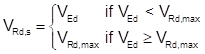
If shear reinforcement is defined in the section, VEd must be less than the minimum between the shear reinforcement force:
![]()
and the maximum design shear force resisted without crushing of concrete compressive struts:
Eurocode 2 (EN 1992-1-1:2004/AC:2008):
![]()
ITER Design Code:
![]()
where:

The shear reinforcement must be less than or equal to (Eurocode 2 only):

Results are written for each end in the CivilFEM results file:
If there is no shear reinforcement defined, the following results can be obtained:
![]()
![]()
![]()
![]()
Tensile strength for the longitudinal reinforcement
![]()
![]() Shear reinforcement not defined
Shear reinforcement not defined
![]() Shear reinforcement defined
Shear reinforcement defined
![]() Shear reinforcement not defined
Shear reinforcement not defined
![]() , Shear reinforcement defined
, Shear reinforcement defined
13.7.2.2 Shear Criterion
The shear criterion indicates whether the shell vertex is valid for the design forces (if it is less than 1, the vertex satisfies the code provisions; whereas if it exceeds 1, the vertex will not be valid). Furthermore, it includes information about how close the design force is to the ultimate strength. The shear criterion is defined as follows:
|
CRT_TOT |
= |
|

A value of 2100 for this criterion indicates that VRd,c, VRd,s or VRd,max are null.
13.7.3 Out-of-Plane Shear Design
13.7.3.1 Checking Whether the Shell Vertex Will Require Shear Reinforcement
First, a check is made to determine if the design shear force VEd is less than or equal to the shear design resistance (VRd,c):
![]()
![]()
with constraints:
![]()
![]()
where:
|
|
= |
|
|
|
|
in MPa |
|
k |
= |
|
|
|
= |
0.15 |
|
|
= |
|
|
|
|
in mm2 |
|
|
|
|
|
|
||
|
|
|
|
|
𝝂 |
= |
|
|
|
= |
|
|
|
|
in N |
According to
article 6.2.2.6, shear force ![]() can be reduced for checking
can be reduced for checking ![]() in members close to the support, with a distance
in members close to the support, with a distance ![]() (position of supports may be introduced to the program with the
name of a node component in the command). In this case, the value of
(position of supports may be introduced to the program with the
name of a node component in the command). In this case, the value of ![]() is multiplied by
is multiplied by ![]() . For
. For ![]() the value of
the value of ![]() is used.
is used.
Results are written for each end in the CivilFEM results file as the following parameters:
|
|
= |
|
|
|
= |
|
13.7.3.2 Maximum Design Shear Force Resisted Without Crushing of the Concrete Compressive Struts
A check is made to ensure that VEd does not exceed the maximum design shear force resisted without crushing of the concrete compressive struts.
Eurocode 2 (EN 1992-1-1:2004/AC:2008):
![]()
ITER Design Code:
![]()
where:

The following results will be saved:
|
|
= |
|
|
|
= |
|
If the design shear force is greater than the shear force required to crush the concrete compressive struts, the reinforcement design will not be feasible; as a result, the reinforcement parameter will be defined as 2100.
In this case, the element will be marked as not designed.
13.7.3.3 Ratio of Reinforcement Required
The required strength of the reinforcement is given by:
The amount of reinforcement per length unit is given by:

The following is also verified (Eurocode 2 only):
![]()
If design shear force is greater than the shear force due to crushing of concrete compressive struts, the reinforcement design will not be feasible; therefore, the parameter containing this datum will be marked with 2100. In this case, the element will be marked as not designed.
ASST and ASSB parameters store the amount of top and bottom reinforcement required due to shear.
Results are written for each element end in the CivilFEM results file as the parameters:
|
VRDS |
= |
|
|
ASSH |
= |
|
|
DSG_CRT |
|
design criterion |
13.8 Check and Design for Out-of-Plane Shear Loadings according to EHE-98
13.8.1 Required Input Data
Shear checking or design according to EHE-98 requires the series of parameters described below:
1) Materials strength properties. These properties are obtained from the material properties associated with each of the shell vertices and for the active time, (see ~CFMP command). Those material properties should be previously defined. The required data are the following ones:
fck characteristic compressive strength of concrete.
fyk characteristic yield strength of the reinforcement.
gc partial safety factor for concrete.
gs partial safety factor for the reinforcement.
2) Shell vertex geometrical data:
th thickness of the shell vertex (~SHLRNF command).
3) Geometrical parameters. Required data are the following:
c bending reinforcement mechanical cover (~SHLRNF command). If different mechanical cover is defined (MCXT, MCXB, MCYT, MCYB), c is the largest mechanical cover among the most tractioned face in each direction
r1 ratio of the longitudinal tensile reinforcement per unit length of the shell:
![]()
where:
Ass the area of the tensile reinforcement (~SHLRNF command).
q angle of the compressive struts of concrete with the longitudinal axis of the member, (parameter THETA of ~SHLRNF command):
![]()
4) Shell vertex reinforcement data. Data concerning reinforcements of the shell vertex must be included within the CivilFEM database. (See ~SHLSHR command). Required data are the following:
Ass area of reinforcement per unit area, (parameter ASS of ~SHLSHR command).
The reinforcement ratio can also be obtained with:
sx, sy spacing of the stirrups in each direction of the shell, (parameters SX and SY of ~SHLSHR command).
f diameter of bars (parameter PHI of ~SHLSHR command).
nx, ny number of stirrups per unit length in each direction of the shell (parameters NX and NY of ~SHLSHR command).
5) Shell vertex internal forces. The shear force that acts on the vertex as well as the concomitant axial force are obtained from the CivilFEM results file (.RCV).
The design shear force (Vrd) is obtained from the shear forces in the X and Y directions:
Which forms an angle with the axis Y:
![]()
The value taken for the design compression force (Td) is the maximum considering all directions:

Design compression force takes into account axial force in x, y directions and in-plane shear using Mohr’s circle stress transformation equations.
The total shear
reinforcement ![]() is
computed from the reinforcements in the X and Y directions, according to
CEB-FIP Model Code 1990 (article 6.4.2.5.):
is
computed from the reinforcements in the X and Y directions, according to
CEB-FIP Model Code 1990 (article 6.4.2.5.):
![]()
13.8.2 Out-of-Plane Shear Checking
13.8.2.1 Checking Failure by Compression
The design shear force (Vrd) is compared with the oblique compression resistance of concrete (Vu1):
![]()
![]()
where:
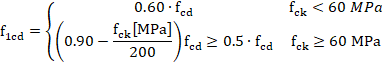
f1cd design compressive strength of concrete.
![]()
K reduction factor by axial forces effect

s’cd effective axial stress in the shell (tension positive)
![]()
For each element end, calculation results are written in the CivilFEM results file as the parameters:
VU1 Ultimate shear strength due to oblique compression of the concrete.
![]()
CRTVU1 Ratio of the design shear (Vrd) to the resistance Vu1.
![]()
13.8.2.1 Checking Failure by Tension in the Web
A check is made to ensure the design shear force (Vrd) is less than or equal to the shear force due to tension in the web (Vu2):
![]()
![]()
Vsu contribution of transverse shear reinforcement in the web to the shear strength.
Vcu contribution of concrete to the shear strength.
Members Without Shear Reinforcement
If shear reinforcement has not been defined:
![]()
![]()
Where:
![]() th and c in mm
th and c in mm
Member With Shear Reinforcement
If shear reinforcement has been defined:
![]()
Where As/s is the shear reinforcement area per unit length
In this case, the concrete contribution to shear strength is:
![]()
Where:
![]() if
if ![]()
![]() if
if ![]()
qe inclination angle of cracks, obtained from:

fct,m average tensile strength of concrete, considered as positive:
![]()
sxd, syd design normal stresses, at the center of gravity, parallel to the longitudinal axis of the member and to the shear force Vd, respectively (tension positive)
Taking ![]()
In addition, the increment in tensile force due to shear force is calculated by:
![]()
For each end, calculation results are written in the CivilFEM results file:
VSU Contribution of the shear reinforcement to the shear strength.
![]()
VCU Contribution of concrete to the shear strength.
![]()
VU2 Ultimate shear strength due to tension in the web.
![]()
CRTVU2 Ratio of the design shear force (Vrd) to the resistance Vu2 .
![]()
If Vu2 = 0, the CTRVU2 criterion is taken as 2100.
The increase of longitudinal reinforcement due to shear is stored in ASST and ASSB parameters (for top and bottom surfaces of the shell respectively).
13.8.2.2 Shear Criterion
The shear criterion indicates whether the shell vertex is valid for the design forces (if it is less than 1, the vertex satisfies the code requirements; whereas if it exceeds 1, the vertex will not be valid). Furthermore, it includes information about how close the design force is to the ultimate strength. The shear criterion is defined as follows:
![]()
For each end, this value is stored in the CivilFEM results file as the parameter CRT_TOT.
A value of 2100 for this criterion indicates that Vu2 is equal to zero.
13.8.3 Out-of-Plane Shear Design
13.8.3.1 Checking Failure by Compression in the Web
The design shear force (Vrd) is compared to the oblique compression resistance of concrete (Vu1):
![]()
![]()
where:
f1cd design compressive strength of concrete
![]()
K reduction coefficient by axial force effect

s’cd effective axial stress in the shell (tension positive)
![]()
For each element end, calculation results are written in the CivilFEM results file:
VU1 Ultimate shear strength due to oblique compression of the concrete in web.
![]()
CRTVU1 Ratio of the design shear force (Vrd) to the resistance Vu1.
![]()
If design shear force is greater than shear force that causes the failure by oblique compression of concrete in the web, the reinforcement design is not feasible. Therefore, the parameter where the reinforcement is stored is marked as 2100.
![]()
In this case, the element will be labeled as not designed.
If there is no failure due to oblique compression, the calculation process continues.
13.8.3.2 Checking If the Shell Will Require Shear Reinforcement
The design shear force Vd must be less than the strength provided by concrete in members without shear reinforcement (Vcu):
![]()
![]()
If the shell does not require shear reinforcement, the following parameters are defined:
VCU Contribution of concrete to the shear strength.
![]()
VU2 Ultimate shear strength by tension.
![]()
VSU Contribution of the shear reinforcement to the shear strength.
![]()
ASSH Required amount of shear reinforcement.
![]()
13.8.3.3 Contribution of the required transverse reinforcement
If the shell requires shear reinforcement the validity condition for sections under shear force is the following one:
![]()
![]()
Vsu contribution of shear transverse reinforcement in the web to shear strength.
Vcu contribution of concrete to shear strength.
![]()
where:
![]() if
if ![]()
![]() if
if ![]()
qe inclination angle of cracks, obtained from:
fct,m average tensile strength of concrete, taken as positive.
![]()
sxd, syd design normal stresses, at the center of gravity, parallel to the longitudinal axis of the member and to the shear force Vd respectively (tension positive)
Taking ![]()
Therefore, the shear reinforcement contribution is given by the equation below:
![]()
For each element end, the value of Vcu and Vsu is stored in the CivilFEM results file as the following parameters:
VCU Contribution of concrete to the shear strength.
![]()
VU2 Ultimate shear strength by tension.
![]()
VSU Contribution of the shear reinforcement to the shear strength.
![]()
13.8.3.4 Required Reinforcement Ratio
Once the shear force that must be carried by the reinforcement has been obtained, the reinforcement can be calculated from the equation below:

The area of designed reinforcement per unit of shell area is stored in the CivilFEM results file as the parameter:
![]()
In this case, the element will be labeled as designed (provided that the design process is correct for all element shell vertices).
If the design is not possible, the reinforcement will be defined as 2100 and the element will not be designed.
13.9 Check and Design for Out-of-Plane Shear Loadings according to EHE-08
13.9.1 Required Input Data
Shear checking or design according to EHE-08 requires the following parameters:
1) Materials strength properties. These properties are obtained from the material properties associated with each one of shell vertices and for the active time, (see ~CFMP command). Those material properties should be previously defined. The required data are the following:
fck characteristic compressive strength of concrete.
fyk characteristic yield strength of reinforcement.
fct,m mean tensile strength of concrete.
gc partial safety factor for concrete.
gs partial safety factor for reinforcement.
2) Shell vertex geometrical data:
th thickness of the shell vertex (~SHLRNF command).
3) Geometrical parameters. Required data are the following:
c Bending reinforcement mechanical cover (~SHLRNF command). If different mechanical cover is defined (MCXT, MCXB, MCYT, MCYB), c is the largest mechanical cover among the most tractioned face in each direction
r1 ratio of the longitudinal tensile reinforcement per unit length of shell:
![]()
where:
Ass the area of the tensile reinforcement (~SHLRNF command).
q angle of the compressive struts of concrete with the longitudinal axis of member, (parameter THETA of ~SHLRNF command):
![]()
4) Shell vertex reinforcement data. Data concerning reinforcements of the shell vertex must be included within CivilFEM database. (See ~SHLSHR command). Required data are the following:
Ass area of reinforcement per unit area, (parameter ASS of ~SHLSHR command).
The reinforcement ratio may also be obtained with:
sx, sy spacing of the stirrups in each direction of the shell, (parameters SX and SY of ~SHLSHR command).
f diameter of bars (parameter PHI of ~SHLSHR command).
nx, ny number of stirrups per unit length in each direction of the shell (parameters NX and NY of ~SHLSHR command).
5) Shell vertex internal forces. The shear force acting on the vertex as well as the concomitant axial force are obtained from the CivilFEM results file (.RCV).
Design shear force (Vrd) is obtained from the shear forces in the X and Y directions:
Which forms an angle with the axis Y:
![]()
The design compression force (Nd) is the maximum force considering all directions:

Design compression force takes into account axial force in x, y directions and in-plane shear using Mohr’s circle stress transformation equations.
The total shear
reinforcement ![]() is
computed from reinforcement in each direction, according to equation LL.123
(Annex LL from EN 1992-2:2005):
is
computed from reinforcement in each direction, according to equation LL.123
(Annex LL from EN 1992-2:2005):
![]()
13.9.2 Out-of-Plane Shear Checking
13.9.2.1 Checking Failure by Compression
The design shear force (Vrd) is compared to the oblique compression resistance of concrete (Vu1):
![]()
where:
f1cd design compressive strength of concrete.
K reduction factor by axial forces effect

s’cd effective axial stress in concrete (compression positive) accounting for the axial stress taken by reinforcement in compression.
For each element end, calculation results are written in the CivilFEM results file:
VU1 Ultimate shear strength due to oblique compression of the concrete.
![]()
CRTVU1 Ratio of the design shear (Vrd) to the resistance Vu1.
![]()
13.9.2.1 Checking Failure by Tension in the Web
The design shear force (Vrd) must be less than or equal to the shear force due to tension in the web (Vu2):
![]()
![]()
Vsu contribution of transverse shear reinforcement in the web to the shear strength.
Vcu contribution of concrete to the shear strength.
Members Without Shear Reinforcement
![]()
![]()
![]()
where:
![]() (Compression positive)
(Compression positive)
![]() d in mm
d in mm
![]()
Member With Shear Reinforcement
![]()
Where As/s is the shear reinforcement area per unit length
In this case, the concrete contribution to shear strength is:
![]()
where:
![]() if
if ![]()
![]() if
if ![]()
qe inclination angle of cracks, obtained from:
sxd, syd design normal stresses, at the center of gravity, parallel to the longitudinal axis of member and to the shear force Vd respectively (tension positive)
Taking ![]()
In addition, the increment in tensile force due to shear force is calculated with the following equation:
![]()
For each end, calculation results are written in the CivilFEM results file:
VSU Contribution of the shear reinforcement to the shear strength.
![]()
VCU Contribution of concrete to the shear strength.
![]()
VU2 Ultimate shear strength by tension in the web.
![]()
CRTVU2 Ratio of the design shear force (Vrd) to the resistance Vu2 .
![]()
If Vu2 = 0, the CTRVU2 criterion is assigned the value of 2100.
The increase in longitudinal reinforcement due to shear is stored in ASST and ASSB parameters (for top and bottom surfaces of the shell respectively).
13.9.2.2 Shear Criterion
The shear criterion indicates whether the shell vertex is valid for the design forces (if it is less than 1, the vertex satisfies the code provisions; whereas if it exceeds 1, the vertex will not be valid). Furthermore, it includes information about how close the design force is to the ultimate strength. The shear criterion is defined as follows:
![]()
For each end, this value is stored in the CivilFEM results file as the parameter CRT_TOT.
A value of 2100 for this criterion indicates Vu2 is equal to zero.
13.9.3 Out-of-Plane Shear Design
13.9.3.1 Checking Compression Failure in the Web
The design shear force (Vrd) is compared to the oblique compression resistance of concrete (Vu1):
![]()
![]()
where:
f1cd design compressive strength of concrete

K reduction coefficient by axial force effect

s’cd effective axial stress in concrete (compression positive) accounting for the axial stress taken by the reinforcement in compression.
For each element end, calculation results are written in the CivilFEM results file:
VU1 Ultimate shear strength due to oblique compression of the concrete in web.
![]()
CRTVU1 Ratio of the design shear force (Vrd) to the resistance Vu1.
![]()
If design shear force is greater than shear force that causes the failure by oblique compression of concrete in the web, the reinforcement design is not feasible. Therefore, the reinforcement parameter will be defined as 2100.
![]()
In this case, the element is labeled as not designed.
If there is no failure due to oblique compression, the calculation process continues.
13.9.3.2 Checking If the Shell Requires Shear Reinforcement
First, a check is made to ensure the design shear force Vd is less than the strength provided by concrete in members without shear reinforcement (Vcu):
![]()
![]()
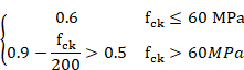
![]()
Where:
![]() (Compression positive)
(Compression positive)
![]() d in mm
d in mm
![]() limited to 60 MPa
limited to 60 MPa
If the shell does not require shear reinforcement, the following parameters are defined:
VCU Contribution of concrete to the shear strength.
![]()
VU2 Ultimate shear strength by tension.
![]()
VSU Contribution of the shear reinforcement to the shear strength.
![]()
ASSH Required amount of shear reinforcement.
![]()
13.9.3.3 Contribution of the Required Transverse Reinforcement
If the shell requires shear reinforcement, sections under shear force will be valid if they satisfy the following condition:
![]()
![]()
Vsu contribution of shear transverse reinforcement in the web to shear strength.
Vcu contribution of concrete to shear strength.
![]()
where:
![]() if
if ![]()
![]() if
if ![]()
qe inclination angle of cracks, obtained from:
sxd, syd design normal stresses at the gravity center, parallel to the longitudinal axis of the member and to the shear force Vd, respectively (tension positive)
Taking ![]()
Therefore, the shear reinforcement contribution is given by the equation below:
![]()
For each element end, the value of Vcu and Vsu is stored in the CivilFEM results file as the following parameters:
VCU Contribution of concrete to the shear strength.
![]()
VU2 Ultimate shear strength by tension.
![]()
VSU Contribution of the shear reinforcement to the shear strength.
![]()
13.9.3.4 Required Reinforcement Ratio
Once the required shear strength of the reinforcement has been obtained, the reinforcement can be calculated from the equation below:
The area of designed reinforcement per unit of shell area is stored in the CivilFEM results file as the parameter:
![]()
In this case, the element will be labeled as designed (provided the design process is correct for all element shell vertices).
If the design is not possible, the reinforcement will be marked as 2100 and the element will not be designed.
13.10 Check and Design for Out-of-Plane Shear Loadings according to Code of Rules 52-101-03 and SP 63.13330.2012
13.10.1 Required Input Data
Shear checking or design according to СП 52-101-03 and СП 63.13330.2012 requires a series of parameters that are described below.
1. Material strength properties. Material properties are assigned to each active shell vertex, (see ~CFMP command). These material properties must be defined prior to checking and design. The required properties are:
![]() design compressive strength of
concrete.
design compressive strength of
concrete.
![]() design tensile strength of concrete.
design tensile strength of concrete.
![]() design yield strength of longitudinal reinforcement.
design yield strength of longitudinal reinforcement.
![]() design yield strength of shear reinforcement.
design yield strength of shear reinforcement.
2. Shell vertex data:
th thickness of the shell vertex (~SHLRNF command - THK).
Data concerning reinforcements of the shell vertex must be included within the
CivilFEM database. (See ~SHLRNF and ~SHLSHR commands). Required properties are:
3. Shell vertex reinforcement data.
D=th-c bending reinforcement mechanical cover (~SHLRNF command MC parameter). If different mechanical cover is defined (MCXT, MCXB, MCYT, MCYB), c is the mechanical cover for the most tensioned face in each direction
4. Code parameters and coefficients. Specific code used for shear calculations must be defined within CivilFEM database (see ~SECMDF command). Required data are the following:
![]() coeffiecient for the
calculation of a concrete band (parameter PHIB1 of ~SECMDF command). By default
coeffiecient for the
calculation of a concrete band (parameter PHIB1 of ~SECMDF command). By default ![]()
5. Shell vertex shear reinforcement data.
Ass area of shear reinforcement per unit of area. This parameter is used for checking (parameter ASSOP of ~SHLSHR command).
The shear reinforcement ratio may also be obtained from:
AssX, AssY area of shear reinforcement per unit of area in each direction of the shell.(parameters ASSOPX and ASSOPY of ~SHLSHR command)
sx, sy spacing of the stirrups in each direction of the shell, (parameters SXOP and SYOP of ~SHLSHR command).
f diameter of bars in mm (parameter PHIOP of ~SHLSHR command).
Nx, Ny number of stirrups per unit length in each direction of the shell (parameters NXOP and NYOP of ~SHLSHR command).
6. Shell vertex internal forces. The shear force acting on the vertex as well as the concomitant membrane force are obtained from the CivilFEM results file (.RCV). For each direction of the shell vertex:
Force Description
Vu Design out-of-plane shear force
Nu Axial force (positive for compression).
13.10.2 Out-of-Plane Shear Checking
13.10.2.1
Coefficient for the effect of compressive and
tensile stress 

13.10.2.2 Checking of a concrete band between inclined sections:
The design shear (Q) must be less than or equal to the design shear resistance:
![]()
Results are written for each end in the CivilFEM results file as the following parameters:
Q1 Design shear resistance on a concrete band.
![]()
CRTQ1 Ratio of the design shear force (Q) to the resistance Q1.
![]()
13.10.2.3 Checking of bent elements in an inclined section:
The following condition must be verified:
![]()
![]() is the shear strength of
concrete.
is the shear strength of
concrete.
![]() is the shear strength of longitudinal reinforcement.
is the shear strength of longitudinal reinforcement.
The contribution of the shear reinforcement and concrete to the shear strength is given by the following equation:
![]()
![]()
Results obtained are written for each end in the CivilFEM results file as the following parameters:
QB Shear strength of concrete
![]()
QSW Shear strength of stirrups.
![]()
Q2 Shear strength of inclined section.
![]()
CRTQ2 Ratio of the design shear force (Q) to the shear strength Q2.
![]()
If ![]() is taken as 2100.
is taken as 2100.
13.10.2.4 Shear criterion
The shear criterion indicates whether the section is valid for the design forces (if it is less than 1, the section satisfies the code prescriptions; whereas if it exceeds 1, the section will not be valid). Furthermore, it includes information about how close the design force is to the ultimate section strength. The shear criterion is defined as follows:
![]()
For each element, this value is stored in the CivilFEM results file as the parameter CRT_#.
The total checking criterion is defined as:
![]()
13.10.3 Out-of-Plane Shear Design
13.10.3.1
Coefficient for the effect of compressive and tensile
stress
13.10.3.2 Checking whether the section will require shear reinforcement
First, we check whether the design shear (Q) is less than or equal to the design shear resistance of a concrete band between inclined sections (Q1):
![]()
![]()
Results are written for each end in the CivilFEM results file as the following parameters:
Q1 Design shear resistance on a concrete band.
![]()
CRTQ1 Ratio of the design shear force (Q) to the resistance Q1.
![]()
If the design shear force is greater than the design shear resistance on a concrete band, the reinforcement design will not be feasible; as a result, the parameter containing this datum will be marked with 2100. It will be:
![]()
In this case, the element will be marked as not designed, and the program will advance to the following element.
13.10.3.3 Calculating the maximum shear force that can be resisted by the concrete
The shear strength of concrete is determined by the following formula:
![]()
![]() is the shear strength of
concrete.
is the shear strength of
concrete.
Results obtained are written for each end in the CivilFEM results file as the following parameters:
QB Shear strength of concrete
![]()
13.10.3.4 Determining the contribution of the required transverse reinforcement
The section validity condition concerning shear force is:
![]()
![]() shear strength of
concrete, calculated in the previous step.
shear strength of
concrete, calculated in the previous step.
![]() shear strength of transverse reinforcement.
shear strength of transverse reinforcement.
The shear reinforcement contribution is given by the following equation:
![]()
![]()
Therefore, the reinforcement contribution should be:
![]()
Results obtained are written for each end in the CivilFEM results file as the following parameters:
QSW Shear strength of stirrups.
![]()
Q2 Shear strength on inclined section.
![]()
13.10.3.5 Calculating the required reinforcement ratio
Once the required shear force of the reinforcement has been obtained, the amount of reinforcement can be calculated from the equation below:
![]()
where:
![]() area of the shear reinforcement per unit
length.
area of the shear reinforcement per unit
length.
The area of designed reinforcement per unit length is stored in the CivilFEM results file as the parameter:
![]()
In this case, the element will be labeled as designed (provided that design process is correct for both element sections).
If it is not possible the design, the reinforcement will be marked as 2100 and the element will not be designed.
13.11 Check and Design for Out-of-Plane Shear Loadings according to ACI 318-05
13.11.1 Required Input Data
The formulas listed in this section utilize U.S. (British) units: inch (in), pound (lb), and second (s).
Shear checking or design according to ACI 318-05 requires the data described below:
1. Material strength properties. Material properties are assigned to each active shell vertex, (see ~CFMP command). These material properties must be defined prior to the check and design process. The required properties are:
f’c specified compressive strength of concrete.
fy specified yield strength of reinforcement.
2. Shell vertex data:
th thickness of the shell vertex (parameter THK of ~SHLRNF command).
Data concerning reinforcements of the shell vertex must be included within the
CivilFEM database. (See ~SHLRNF and ~SHLSHR commands). Required properties are:
3. Shell vertex reinforcement data.
c bending reinforcement mechanical cover (parameter MC of ~SHLRNF command). If different mechanical cover is defined (MCXT, MCXB, MCYT, MCYB), c is the mechanical cover for the most tractioned face in each direction
Ass the area of bending reinforcement per unit length. This parameter is used for checking (parameters ASSXT, ASSXB, ASSYT, ASSYB of ~SHLRNF command).
4. Shell vertex shear reinforcement data.
Ass area of shear reinforcement per unit of area. This parameter is used for checking (parameter ASSOP of ~SHLSHR command).
The shear reinforcement ratio may also be obtained from:
AssX, AssY area of shear reinforcement per unit of area in each direction of the shell. (parameters ASSOPX and ASSOPY of ~SHLSHR command)
sx, sy spacing of the stirrups in each direction of the shell, (parameters SXOP and SYOP of ~SHLSHR command).
f diameter of bars in mm (parameter PHIOP of ~SHLSHR command).
Nx, Ny number of stirrups per unit length in each direction of the shell (parameters NXOP and NYOP of ~SHLSHR command).
5. Shell vertex internal forces. The shear force acting on the vertex as well as the concomitant membrane force are obtained from the CivilFEM results file (.RCV). For each direction of the shell vertex:
Force Description
Vu Design out-of-plane shear force
Nu Axial force (positive for compression).
13.11.2 Out-of-Plane Shear Checking
13.11.2.1 Shear Strength Provided by Concrete
The shear strength provided by concrete (Vc) is calculated with the following expression:
![]()
(ACI 318-05 Eqn:11-3)
where:
bw = 1 (unit length)
![]() square root of specified
compressive strength of concrete, in psi (always taken as less than 100 psi).
square root of specified
compressive strength of concrete, in psi (always taken as less than 100 psi).
For sections subject to a compressive axial force,
![]()
(ACI 318-05 Eqn:11-4)
where:
Nu/(th·bw) expressed in psi.
If section is subjected to a tensile force so that the tensile stress is less than 500 psi:
![]()
(ACI 318-05 Eqn:11-8)
If the shell is subjected to a tensile force so that the tensile stress exceeds 500 psi, it is assumed Vc=0.
The calculation result for all elements is stored in the CivilFEM results file as the parameter VC (# is the direction of the shell, X or Y):
VC_# Shear strength provided by concrete.
![]()
13.11.2.2 Shear Strength Provided by Shear Reinforcement
The strength provided by the shear reinforcement (Vs) is calculated with the following expression:
![]()
(ACI 318-05 Eqn.11-15)
The calculation result for all elements is stored in the CivilFEM results file as the parameter VS (# is the direction of the shell, X or Y direction):
VS_# Shear strength provided by transverse reinforcement.
![]()
The following condition must be satisfied:
![]()
(ACI 318-01 Eqn.11.5.6.8)
This condition is reflected in the total criterion. For this condition that takes into account both directions, value of c is taken as the largest of c for each direction
13.11.2.3 Nominal Shear Strength
The nominal shear strength (Vn) is the sum of the provided by concrete and by the shear reinforcement:
![]()
This nominal strength, is stored in the CivilFEM results file as the parameter VN (# is the direction of the shell, X or Y):
VN_# Nominal shear strength.
![]()
13.11.2.4 Minimum Reinforcement
If reinforcement is required, the minimum allowable value is:

(ACI 318-05 Eqn.11-13)
13.11.2.5 Shear Criterion
The shell vertex will be valid for shear if the following condition is satisfied and if the reinforcement is greater than the minimum required:
![]()
(ACI 318-05 Eqn.11-1 and 11-2)
Where f is the strength reduction factor (defined in ~CHKCON command). Therefore, the shear criterion for the validity of the shell vertex is as follows:
![]()
For each element, this value is stored in the CivilFEM results file as the parameter CRT_#.
If the strength provided by concrete is null and the shear reinforcement is not defined in the shell vertex, and the criterion is equal to 2100.
The f·Vn value is stored in CivilFEM results file as the parameter VFI_#.
The total checking criterion is defined as:

13.11.3 Out-of-Plane Shear Design
13.11.3.1 Shear Strength Provided by Concrete
The shear strength provided by the concrete (Vc) is calculated by:
![]()
(ACI 318-05 Eqn.11-8)
where:
![]() = 1 (unit length)
= 1 (unit length)
![]() square root of specified
compressive strength of concrete, in psi (always taken as less than 100 psi).
square root of specified
compressive strength of concrete, in psi (always taken as less than 100 psi).
For sections subject to a compressive axial force,
![]()
(ACI 318-05 Eqn.11-4)
where:
Nu/(th·bw) expressed in units of psi.
If the section is subjected to a tensile force such that the tensile stress is less than 500 psi,
![]()
(ACI 318-05 Eqn.11-8)
If the shell is subjected to a tensile force such that the tensile stress exceeds 500 psi, it is assumed that Vc=0.
The calculation result for all element ends is stored in the CivilFEM results file as the parameter VC (# is the direction of the shell, X or Y):
VC_# Shear strength provided by concrete.
![]()
13.11.3.2 Required Reinforcement Contribution
The shell must satisfy the following condition to resist the shear force:
![]()
(ACI 318-05 Eqn.11-1 and 11-2)
where: ![]() is the strength reduction factor (defined in ~DIMCON
command).
is the strength reduction factor (defined in ~DIMCON
command).
Therefore, the required shear strength of the reinforcement is:
![]()
Calculated results are stored in the CivilFEM results file for both element ends as the parameter VS (# is the direction of the shell, X or Y):
VS_# Shear resistance provided by the transverse reinforcement.
![]()
The following condition must be satisfied:
![]()
(ACI 318-01 Eqn.11.5.6.8)
If the required shear strength of the reinforcement does not satisfy the expression above, the shell vertex cannot be designed; therefore, the reinforcement parameter will be set as 2100.
![]()
In this case, the element will be labeled as not designed.
For this condition that takes into account both directions, value of c is taken as the largest of c for each direction
13.11.3.3 Required Reinforcement
Once the required shear strength of the reinforcement has been determined, the reinforcement is calculated as the maximum of the following expressions (for both X and Y directions):
![]() for both X and Y directions
for both X and Y directions
(ACI 318-05 Eqn.11-15)
These reinforcement areas will be proportionally increased, if needed, to reach the minimum required ratio:

(ACI 318-05 Eqn.11-13)
The area of the designed reinforcement per unit length is stored in the CivilFEM results file as:

In this case, the element will be labeled as designed (providing the design process is correct for all element ends).
13.12 Check and Design for Out-of-Plane Shear Loadings according to ACI 318-14
13.12.1 Required Input Data
The formulas listed in this section utilize U.S. (British) units: inch (in), pound (lb), and second (s).
Shear checking or design according to ACI 318-14 requires the data described below:
6. Material strength properties. Material properties are assigned to each active shell vertex, (see ~CFMP command). These material properties must be defined prior to the check and design process. The required properties are:
f’c specified compressive strength of concrete.
fy specified yield strength of reinforcement.
![]() modification factor for lightweight concrete.
modification factor for lightweight concrete.
7. Shell vertex data:
th thickness of the shell vertex (parameter THK of ~SHLRNF command).
Data concerning reinforcements of the shell vertex must be included within the
CivilFEM database. (See ~SHLRNF and ~SHLSHR commands). Required properties are:
8. Shell vertex reinforcement data.
c bending reinforcement mechanical cover (parameter MC of ~SHLRNF command). If different mechanical cover is defined (MCXT, MCXB, MCYT, MCYB), c is the mechanical cover for the most tractioned face in each direction
Ass the area of bending reinforcement per unit length. This parameter is used for checking (parameters ASSXT, ASSXB, ASSYT, ASSYB of ~SHLRNF command).
9. Shell vertex shear reinforcement data.
Ass area of shear reinforcement per unit of area. This parameter is used for checking (parameter ASSOP of ~SHLSHR command).
The shear reinforcement ratio may also be obtained from:
AssX, AssY area of shear reinforcement per unit of area in each direction of the shell. (parameters ASSOPX and ASSOPY of ~SHLSHR command)
sx, sy spacing of the stirrups in each direction of the shell, (parameters SXOP and SYOP of ~SHLSHR command).
f diameter of bars in mm (parameter PHIOP of ~SHLSHR command).
Nx, Ny number of stirrups per unit length in each direction of the shell (parameters NXOP and NYOP of ~SHLSHR command).
10. Shell vertex internal forces. The shear force acting on the vertex as well as the concomitant membrane force are obtained from the CivilFEM results file (.RCV). For each direction of the shell vertex:
Force Description
Vu Design out-of-plane shear force
Nu Axial force (positive for compression).
13.12.2 Out-of-Plane Shear Checking
13.12.2.1 Shear Strength Provided by Concrete
The shear strength provided by concrete (Vc) is calculated with the following expression:
![]()
(ACI 318-14)
where:
bw = 1 (unit length)
![]() square root of specified
compressive strength of concrete, in psi (always taken as less than 100 psi).
square root of specified
compressive strength of concrete, in psi (always taken as less than 100 psi).
For sections subject to a compressive axial force,
![]()
(ACI 318-14)
where:
Nu/(th·bw) expressed in psi.
If section is subjected to a tensile force so that the tensile stress is less than 500 psi:
![]()
(ACI 318-14)
If the shell is subjected to a tensile force so that the tensile stress exceeds 500 psi, it is assumed Vc=0.
The calculation result for all elements is stored in the CivilFEM results file as the parameter VC (# is the direction of the shell, X or Y):
VC_# Shear strength provided by concrete.
![]()
13.12.2.2 Shear Strength Provided by Shear Reinforcement
The strength provided by the shear reinforcement (Vs) is calculated with the following expression:
![]()
(ACI 318-14)
The calculation result for all elements is stored in the CivilFEM results file as the parameter VS (# is the direction of the shell, X or Y direction):
VS_# Shear strength provided by transverse reinforcement.
![]()
The following condition must be satisfied:
![]()
(ACI 318-14)
This condition is reflected in the total criterion. For this condition that takes into account both directions, value of c is taken as the largest of c for each direction
13.12.2.3 Nominal Shear Strength
The nominal shear strength (Vn) is the sum of the provided by concrete and by the shear reinforcement:
![]()
This nominal strength, is stored in the CivilFEM results file as the parameter VN (# is the direction of the shell, X or Y):
VN_# Nominal shear strength.
![]()
13.12.2.4 Minimum Reinforcement
If reinforcement is required, the minimum allowable value is:
(ACI 318-05 Eqn.11-13)
13.12.2.5 Shear Criterion
The shell vertex will be valid for shear if the following condition is satisfied and if the reinforcement is greater than the minimum required:
![]()
(ACI 318-05 Eqn.11-1 and 11-2)
Where f is the strength reduction factor (defined in ~CHKCON command). Therefore, the shear criterion for the validity of the shell vertex is as follows:
![]()
For each element, this value is stored in the CivilFEM results file as the parameter CRT_#.
If the strength provided by concrete is null and the shear reinforcement is not defined in the shell vertex, and the criterion is equal to 2100.
The f·Vn value is stored in CivilFEM results file as the parameter VFI_#.
The total checking criterion is defined as:
13.12.3 Out-of-Plane Shear Design
13.12.3.1 Shear Strength Provided by Concrete
The shear strength provided by the concrete (Vc) is calculated by:
![]()
(ACI 318-14)
where:
![]() = 1 (unit length)
= 1 (unit length)
![]() square root of specified
compressive strength of concrete, in psi (always taken as less than 100 psi).
square root of specified
compressive strength of concrete, in psi (always taken as less than 100 psi).
For sections subject to a compressive axial force,
![]()
(ACI 318-14)
where:
Nu/(th·bw) expressed in units of psi.
If the section is subjected to a tensile force such that the tensile stress is less than 500 psi,
![]()
(ACI 318-14)
If the shell is subjected to a tensile force such that the tensile stress exceeds 500 psi, it is assumed that Vc=0.
The calculation result for all element ends is stored in the CivilFEM results file as the parameter VC (# is the direction of the shell, X or Y):
VC_# Shear strength provided by concrete.
![]()
13.12.3.2 Required Reinforcement Contribution
The shell must satisfy the following condition to resist the shear force:
![]()
(ACI 318-14)
where: ![]() is the strength reduction factor (defined in ~DIMCON
command).
is the strength reduction factor (defined in ~DIMCON
command).
Therefore, the required shear strength of the reinforcement is:
![]()
Calculated results are stored in the CivilFEM results file for both element ends as the parameter VS (# is the direction of the shell, X or Y):
VS_# Shear resistance provided by the transverse reinforcement.
![]()
The following condition must be satisfied:
![]()
(ACI 318-14)
If the required shear strength of the reinforcement does not satisfy the expression above, the shell vertex cannot be designed; therefore, the reinforcement parameter will be set as 2100.
![]()
In this case, the element will be labeled as not designed.
For this condition that takes into account both directions, value of c is taken as the largest of c for each direction
13.12.3.3 Required Reinforcement
Once the required shear strength of the reinforcement has been determined, the reinforcement is calculated as the maximum of the following expressions (for both X and Y directions):
![]() for both X and Y directions
for both X and Y directions
(ACI 318-14)
These reinforcement areas will be proportionally increased, if needed, to reach the minimum required ratio:
(ACI 318-14)
The area of the designed reinforcement per unit length is stored in the CivilFEM results file as:
In this case, the element will be labeled as designed (providing the design process is correct for all element ends).
13.13 Check and Design for Out-of-Plane Shear Loadings according to ACI 318-19
13.13.1 Required Input Data
The formulas listed in this section utilize U.S. (British) units: inch (in), pound (lb), and second (s).
Shear checking or design according to ACI 318-19 requires the data described below:
11. Material strength properties. Material properties are assigned to each active shell vertex, (see ~CFMP command). These material properties must be defined prior to the check and design process. The required properties are:
f’c specified compressive strength of concrete.
fy specified yield strength of reinforcement.
![]() modification factor for lightweight concrete.
modification factor for lightweight concrete.
12. Shell vertex data:
th thickness of the shell vertex (parameter THK of ~SHLRNF command).
Data concerning reinforcements of the shell vertex must be included within the
CivilFEM database. (See ~SHLRNF and ~SHLSHR commands). Required properties are:
13. Shell vertex reinforcement data.
c bending reinforcement mechanical cover (parameter MC of ~SHLRNF command). If different mechanical cover is defined (MCXT, MCXB, MCYT, MCYB), c is the mechanical cover for the most tractioned face in each direction
Ass the area of bending reinforcement per unit length. This parameter is used for checking (parameters ASSXT, ASSXB, ASSYT, ASSYB of ~SHLRNF command).
14. Shell vertex shear reinforcement data.
Ass area of shear reinforcement per unit of area. This parameter is used for checking (parameter ASSOP of ~SHLSHR command).
The shear reinforcement ratio may also be obtained from:
AssX, AssY area of shear reinforcement per unit of area in each direction of the shell. (parameters ASSOPX and ASSOPY of ~SHLSHR command)
sx, sy spacing of the stirrups in each direction of the shell, (parameters SXOP and SYOP of ~SHLSHR command).
f diameter of bars in mm (parameter PHIOP of ~SHLSHR command).
Nx, Ny number of stirrups per unit length in each direction of the shell (parameters NXOP and NYOP of ~SHLSHR command).
15. Shell vertex internal forces. The shear force acting on the vertex as well as the concomitant membrane force are obtained from the CivilFEM results file (.RCV). For each direction of the shell vertex:
Force Description
Vu Design out-of-plane shear force
Nu Axial force (positive for compression).
13.13.2 Out-of-Plane Shear Checking
13.13.2.1 Minimum Reinforcement
If minimum reinforcement is required, the minimum allowable is the greater value of:


13.13.2.2 Shear Strength Provided by Concrete
The shear strength provided by concrete (Vc) is calculated with the following expression:
![]()
![]()
where:
bw = 1 (unit length)
![]() square root of specified
compressive strength of concrete, in psi (always taken as less than 100 psi).
square root of specified
compressive strength of concrete, in psi (always taken as less than 100 psi).
![]() ratio of tensile reinforcement defined by the user.
Value is taken as the greater of defined and the one that
ratio of tensile reinforcement defined by the user.
Value is taken as the greater of defined and the one that ![]() is equal to
is equal to ![]()
![]() N is positive for compression and negative for tension
N is positive for compression and negative for tension
![]() Size effect modification factor, determined as:
Size effect modification factor, determined as:

Limits for Vc are taken as:
0![]()
The calculation result for all elements is stored in the CivilFEM results file as the parameter VC (# is the direction of the shell, X or Y):
VC_# Shear strength provided by concrete.
![]()
13.13.2.3 Shear Strength Provided by Shear Reinforcement
The strength provided by the shear reinforcement (Vs) is calculated with the following expression:
![]()
(ACI 318-19)
The calculation result for all elements is stored in the CivilFEM results file as the parameter VS (# is the direction of the shell, X or Y direction):
VS_# Shear strength provided by transverse reinforcement.
![]()
13.13.2.4 Nominal Shear Strength
The nominal shear strength (Vn) is the sum of the provided by concrete and by the shear reinforcement:
![]()
This nominal strength, is stored in the CivilFEM results file as the parameter VN (# is the direction of the shell, X or Y):
VN_# Nominal shear strength.
![]()
13.13.2.5 Shear Criterion
The shell vertex will be valid for shear if the following condition is satisfied and if the reinforcement is greater than the minimum required:
![]()
Where f is the strength reduction factor. Therefore, the shear criterion for the validity of the shell vertex is as follows:
![]()
For each element, this value is stored in the CivilFEM results file as the parameter CRT_#.
If the strength provided by concrete is null and the shear reinforcement is not defined in the shell vertex, and the criterion is equal to 2100.
The cross-sectional dimensions limit is checked. If end doesn´t fill the next equation, the criterion is equal to 2100

The f·Vn value is stored in CivilFEM results file as the parameter VFI_#.
The total checking criterion is defined as:
![]()
13.13.3 Out-of-Plane Shear Design
13.13.3.1 Minimum Reinforcement
If minimum reinforcement is required, the minimum allowable is the greater value of:
13.13.3.2 Shear Strength Provided by Concrete
The shear
strength provided by the concrete (Vc) is calculated assuming ![]() :
:
![]()
where:
![]() = 1 (unit length)
= 1 (unit length)
![]() square root of specified
compressive strength of concrete, in psi (always taken as less than 100 psi).
square root of specified
compressive strength of concrete, in psi (always taken as less than 100 psi).
![]() ratio of tensile reinforcement defined by the user.
Value is taken as the greater of defined and the one that
ratio of tensile reinforcement defined by the user.
Value is taken as the greater of defined and the one that ![]() is equal to
is equal to ![]()
![]() N is positive for compression and negative for tension
N is positive for compression and negative for tension
The calculation result for all element ends is stored in the CivilFEM results file as the parameter VC (# is the direction of the shell, X or Y):
VC_# Shear strength provided by concrete.
![]()
13.13.3.3 Required Reinforcement Contribution
The shell must satisfy the following condition to resist the shear force:
![]()
where: ![]() is the strength reduction factor.
is the strength reduction factor.
Therefore, the required shear strength of the reinforcement is:
![]()
Calculated results are stored in the CivilFEM results file for both element ends as the parameter VS (# is the direction of the shell, X or Y):
VS_# Shear resistance provided by the transverse reinforcement.
![]()
13.13.3.4 Required Reinforcement
Once the required shear strength of the reinforcement has been determined, the reinforcement is calculated as the maximum of the following expressions (for both X and Y directions):
![]() for both X and Y directions
for both X and Y directions
If ![]() and
and ![]() is required (
is required ( ![]() ) then:
) then:![]()
If ![]() and
and ![]() is not required Vc is recalculated using the formula for
is not required Vc is recalculated using the formula for ![]() :
:
![]()
where:
![]() Size effect modification factor, determined as:
Size effect modification factor, determined as:
Then ![]() is recalculated with the new value of Vc
is recalculated with the new value of Vc
The area of the designed reinforcement per unit length is stored in the CivilFEM results file as:
In this case, the element will be labeled as designed (providing the design process is correct for all element ends).
13.14 Check and Design for Out-of-Plane Shear Loadings according to ACI 349-01 and ACI 349-06 (Reinforced Concrete)
13.14.1 Required Input Data
Shear checking or design according to ACI 349-01 requires a series of parameters that are described below. The formulas listed in this section utilize U.S. (British) units: inch (in), pound (lb), and second (s).
7. Material strength properties. Material properties are assigned to each active shell vertex, (see ~CFMP command). These material properties must be defined prior to checking and design. The required properties are:
f’c specified compressive strength of concrete.
fy specified yield strength of reinforcement.
8. Shell vertex data:
th thickness of the shell vertex (~SHLRNF command - THK).
Data concerning reinforcements of the shell vertex must be included within the
CivilFEM database. (See ~SHLRNF and ~SHLSHR commands). Required properties are:
9. Shell vertex reinforcement data.
c bending reinforcement mechanical cover (~SHLRNF command -MC). If different mechanical cover is defined (MCXT, MCXB, MCYT, MCYB), c is the mechanical cover for the most tractioned face in each direction
Ass the area of bending reinforcement per unit length. This parameter is used for checking(~SHLRNF command ASSXT, ASSXB, ASSYT, ASSYB).
10. Shell vertex shear reinforcement data.
Ass area of shear reinforcement per unit of area. This parameter is used for checking (parameter ASSOP of ~SHLSHR command).
The shear reinforcement ratio may also be obtained from:
AssX, AssY area of shear reinforcement per unit of area in each direction of the shell.(parameters ASSOPX and ASSOPY of ~SHLSHR command)
sx, sy spacing of the stirrups in each direction of the shell, (parameters SXOP and SYOP of ~SHLSHR command).
f diameter of bars in mm (parameter PHIOP of ~SHLSHR command).
Nx, Ny number of stirrups per unit length in each direction of the shell (parameters NXOP and NYOP of ~SHLSHR command).
11. Shell vertex internal forces. The shear force acting on the vertex as well as the concomitant membrane force are obtained from the CivilFEM results file (.RCV). For each direction of the shell vertex:
Force Description
Vu Design out-of-plane shear force
Nu Axial force (positive for compression).
13.14.2 Out-of-Plane Shear Checking
13.14.2.1 Shear Strength Provided by Concrete
The shear strength provided by concrete (Vc) is calculated by:
![]()
(ACI 349-01 Eqn:11-3)
where:
bw = 1 (unit length)
![]() square root of specified
compressive strength of concrete, in psi (always taken as less than 100 psi).
square root of specified
compressive strength of concrete, in psi (always taken as less than 100 psi).
For sections subject to an axial compressive force,
![]()
(ACI 349-01 Eqn:11-4)
where:
Nu/(th·bw) expressed in units of psi.
If the section is subjected to a tensile force such that the tensile stress is less than 500 psi then,
![]()
(ACI 349-01 Eqn:11-8)
If the shell is subjected to a tensile force so that the tensile stress exceeds 500 psi, it is assumed Vc=0.
The calculation result for all elements is stored in the CivilFEM results file as the parameter VC (# is the direction of the shell, X or Y):
VC_# Shear strength provided by concrete.
![]()
13.14.2.2 Shear strength provided by shear reinforcement
The strength provided by shear reinforcement (Vs) is calculated with the following expression:
![]()
(ACI 349-01 Eqn.11-15)
The calculated result for all elements is stored in the CivilFEM results file as the parameter VS (# is the direction of the shell, X or Y):
VS_# Shear strength provided by transverse reinforcement.
![]()
The following condition must be satisfied:
![]()
(ACI 349-01 Eqn.11.5.6.8)
This condition is reflected in the total criterion. For this condition that takes into account both directions, value of c is taken as the largest of c for each direction
13.14.2.3 Nominal shear strength
The nominal shear strength (Vn) is the sum of the concrete and shear reinforcement components calculated previously:
![]()
This nominal strength, is stored in the CivilFEM results file as the parameter VN (# is the direction of the shell, X or Y):
VN_# Nominal shear strength.
![]()
13.14.2.4 Minimum reinforcement
If reinforcement is required, the minimum allowable value is:
(ACI 349-01 Eqn.11-13)
13.14.2.5 Shear criterion
The shell vertex will be valid for shear if the following condition is satisfied:
![]()
(ACI 349-01 Eqn.11-1 and 11-2)
where f is strength reduction factor (defined in ~CHKCON command), and if the reinforcement is greater than the minimum required. Therefore, the validity shear criterion is defined as follows:
![]()
For each element, this value is stored in the CivilFEM results file as the parameter CRT_#.
If the strength provided by concrete is null and the shear reinforcement is not defined in the shell vertex, the criterion is set equal to 2100.
The f·Vn value is stored in the CivilFEM results file as the parameter VFI_#.
The total checking criterion is defined as:
13.14.3 Out-of-Plane Shear Design
13.14.3.1 Shear strength provided by concrete
The shear strength provided by concrete (Vc) is calculated with the following expression:
![]()
(ACI 349-01 Eqn.11-3)
where:
![]() = 1 (unit length)
= 1 (unit length)
![]() square root of specified
compressive strength of concrete, in psi (it is always taken as less than 100
psi).
square root of specified
compressive strength of concrete, in psi (it is always taken as less than 100
psi).
For sections subject to a compressive axial force,
![]()
(ACI 349-01 Eqn.11-4)
Where:
Nu/(th·bw) is expressed in psi.
If the section is subjected to a tensile force such that the tensile stress is less than 500 psi:
![]()
(ACI 349-01 Eqn.11-8)
If the shell is subjected to a tensile force such that the tensile stress exceeds 500 psi, it is assumed that Vc=0.
The calculation result for all elements is stored in the CivilFEM results file as the parameter VC (# is the direction of the shell, X or Y):
VC_# Shear strength provided by concrete.
![]()
13.14.3.2 Required reinforcement contribution
The shell must satisfy the following condition to resist the shear force:
![]()
(ACI 349-01 Eqn.11-1 and 11-2)
Where f is the strength reduction factor (defined in ~DIMCON command).
Therefore, the shear force the reinforcement must support is:
![]()
Calculation results are stored in the CivilFEM results file for all elements as the parameter VS (# is the direction of the shell, X or Y):
VS_# Shear resistance provided by the transverse reinforcement.
![]()
The following condition must be satisfied:
![]()
(ACI 349-01 Eqn.11.5.6.8)
If the shear force the reinforcement must support does not satisfy the expression above, the shell vertex cannot be designed, so the parameters where the reinforcement is stored are set to 2100. Then:
![]()
In this case, the element will labeled as not designed.
For this condition that takes into account both directions, value of c is taken as the largest of c for each direction
13.14.3.3 Required reinforcement
Once the shear force that the shear reinforcement must support has been obtained, the reinforcement is calculated as follows:
![]()
for each direction X and Y
(ACI 349-01 Eqn.11-15)
These reinforcement areas will be increased proportionally, if needed, to reach the minimum required ratio:
(ACI 349-01 Eqn.11-13)
The area of the designed reinforcement per unit of area is stored in the CivilFEM results file as:
In this case, the element will be marked as designed (providing the design process is correct for all element directions).
13.15 Check and Design for Out-of-Plane Shear Loadings according to ACI 349-13 (Reinforced Concrete)
13.15.1 Required Input Data
Shear checking or design according to ACI 349-13 requires a series of parameters that are described below. The formulas listed in this section utilize U.S. (British) units: inch (in), pound (lb), and second (s).
12. Material strength properties. Material properties are assigned to each active shell vertex, (see ~CFMP command). These material properties must be defined prior to checking and design. The required properties are:
f’c specified compressive strength of concrete.
fy specified yield strength of reinforcement.
![]() modification factor for lightweight concrete.
modification factor for lightweight concrete.
13. Shell vertex data:
th thickness of the shell vertex (~SHLRNF command - THK).
Data concerning reinforcements of the shell vertex must be included within the
CivilFEM database. (See ~SHLRNF and ~SHLSHR commands). Required properties are:
14. Shell vertex reinforcement data.
c bending reinforcement mechanical cover (~SHLRNF command -MC). If different mechanical cover is defined (MCXT, MCXB, MCYT, MCYB), c is the mechanical cover for the most tractioned face in each direction
Ass the area of bending reinforcement per unit length. This parameter is used for checking(~SHLRNF command ASSXT, ASSXB, ASSYT, ASSYB).
15. Shell vertex shear reinforcement data.
Ass area of shear reinforcement per unit of area. This parameter is used for checking (parameter ASSOP of ~SHLSHR command).
The shear reinforcement ratio may also be obtained from:
AssX, AssY area of shear reinforcement per unit of area in each direction of the shell.(parameters ASSOPX and ASSOPY of ~SHLSHR command)
sx, sy spacing of the stirrups in each direction of the shell, (parameters SXOP and SYOP of ~SHLSHR command).
f diameter of bars in mm (parameter PHIOP of ~SHLSHR command).
Nx, Ny number of stirrups per unit length in each direction of the shell (parameters NXOP and NYOP of ~SHLSHR command).
16. Shell vertex internal forces. The shear force acting on the vertex as well as the concomitant membrane force are obtained from the CivilFEM results file (.RCV). For each direction of the shell vertex:
Force Description
Vu Design out-of-plane shear force
Nu Axial force (positive for compression).
13.15.2 Out-of-Plane Shear Checking
13.15.2.1 Shear Strength Provided by Concrete
The shear strength provided by concrete (Vc) is calculated by:
![]()
(ACI 349-13)
where:
bw = 1 (unit length)
![]() square root of specified
compressive strength of concrete, in psi (always taken as less than 100 psi).
square root of specified
compressive strength of concrete, in psi (always taken as less than 100 psi).
For sections subject to an axial compressive force,
![]()
(ACI 349-13)
where:
Nu/(th·bw) expressed in units of psi.
If the section is subjected to a tensile force such that the tensile stress is less than 500 psi then,
![]()
(ACI 349-13)
If the shell is subjected to a tensile force so that the tensile stress exceeds 500 psi, it is assumed Vc=0.
The calculation result for all elements is stored in the CivilFEM results file as the parameter VC (# is the direction of the shell, X or Y):
VC_# Shear strength provided by concrete.
![]()
13.15.2.2 Shear strength provided by shear reinforcement
The strength provided by shear reinforcement (Vs) is calculated with the following expression:
![]()
(ACI 349-13)
The calculated result for all elements is stored in the CivilFEM results file as the parameter VS (# is the direction of the shell, X or Y):
VS_# Shear strength provided by transverse reinforcement.
![]()
The following condition must be satisfied:
![]()
(ACI 349-13)
This condition is reflected in the total criterion. For this condition that takes into account both directions, value of c is taken as the largest of c for each direction
13.15.2.3 Nominal shear strength
The nominal shear strength (Vn) is the sum of the concrete and shear reinforcement components calculated previously:
![]()
This nominal strength, is stored in the CivilFEM results file as the parameter VN (# is the direction of the shell, X or Y):
VN_# Nominal shear strength.
![]()
13.15.2.4 Minimum reinforcement
If reinforcement is required, the minimum allowable value is:
(ACI 349-13)
13.15.2.5 Shear criterion
The shell vertex will be valid for shear if the following condition is satisfied:
![]()
(ACI 349-13)
where f is strength reduction factor (defined in ~CHKCON command), and if the reinforcement is greater than the minimum required. Therefore, the validity shear criterion is defined as follows:
![]()
For each element, this value is stored in the CivilFEM results file as the parameter CRT_#.
If the strength provided by concrete is null and the shear reinforcement is not defined in the shell vertex, the criterion is set equal to 2100.
The f·Vn value is stored in the CivilFEM results file as the parameter VFI_#.
The total checking criterion is defined as:
13.15.3 Out-of-Plane Shear Design
13.15.3.1 Shear strength provided by concrete
The shear strength provided by concrete (Vc) is calculated with the following expression:
![]()
(ACI 349-13)
where:
![]() = 1 (unit length)
= 1 (unit length)
![]() square root of specified
compressive strength of concrete, in psi (it is always taken as less than 100
psi).
square root of specified
compressive strength of concrete, in psi (it is always taken as less than 100
psi).
For sections subject to a compressive axial force,
![]()
(ACI 349-13)
Where:
Nu/(th·bw) is expressed in psi.
If the section is subjected to a tensile force such that the tensile stress is less than 500 psi:
![]()
(ACI 349-13)
If the shell is subjected to a tensile force such that the tensile stress exceeds 500 psi, it is assumed that Vc=0.
The calculation result for all elements is stored in the CivilFEM results file as the parameter VC (# is the direction of the shell, X or Y):
VC_# Shear strength provided by concrete.
![]()
13.15.3.2 Required reinforcement contribution
The shell must satisfy the following condition to resist the shear force:
![]()
(ACI 349-13)
Where f is the strength reduction factor (defined in ~DIMCON command).
Therefore, the shear force the reinforcement must support is:
![]()
Calculation results are stored in the CivilFEM results file for all elements as the parameter VS (# is the direction of the shell, X or Y):
VS_# Shear resistance provided by the transverse reinforcement.
![]()
The following condition must be satisfied:
![]()
(ACI 349-13)
If the shear force the reinforcement must support does not satisfy the expression above, the shell vertex cannot be designed, so the parameters where the reinforcement is stored are set to 2100. Then:
![]()
In this case, the element will labeled as not designed.
For this condition that takes into account both directions, value of c is taken as the largest of c for each direction
13.15.3.3 Required reinforcement
Once the shear force that the shear reinforcement must support has been obtained, the reinforcement is calculated as follows:
![]()
for each direction X and Y
(ACI 349-13)
These reinforcement areas will be increased proportionally, if needed, to reach the minimum required ratio:
(ACI 349-13)
The area of the designed reinforcement per unit of area is stored in the CivilFEM results file as:
In this case, the element will be marked as designed (providing the design process is correct for all element directions).
13.16 Check and Design for In-plane Shear Loadings according to ACI 349-01and ACI 349-06
13.16.1 Required Input Data
Shear checking or design according to ACI 349 require the parameters described below. The formulas listed in this section utilize U.S. (British) units: inch (in), pound (lb), and second (s).
1. Material strength properties. This data is obtained from the material properties assigned to each active shell vertex, (see ~CFMP command). These material properties must be defined prior to check and design. The required properties are:
f’c specified compressive strength of concrete.
fy specified yield strength of reinforcement.
2. Shell vertex data:
th thickness of the shell vertex (~SHLRNF command - THK).
Data concerning reinforcements of the shell vertex must be included within CivilFEM database. (See ~SHLRNF and ~SHLIPSH commands). Required properties are:
3. Shell vertex reinforcement data.
c bending reinforcement mechanical cover (~SHLRNF command -MC).
Ass the area of bending reinforcement per unit length. This parameter is used for checking(~SHLRNF command ASSXT, ASSXB, ASSYT, ASSYB).
4. Shell vertex shear reinforcement data.
AssipX, AssipX area of in plane shear reinforcement per unit of length in each direction of the shell. These parameters are used for checking (parameter ASSIPX and ASSIPY of ~SHLIPSH command).
5. Shell vertex internal forces. The shear force that acts on the vertex as well as the concomitant membrane force are obtained from the CivilFEM results file (.RCV). For each direction of the shell vertex:
Force Description
Vu Design in plane shear force
Nu Membrane force (positive for compression) perpendicular to Vu
6. Type of check/design. In-plane shear check/design according to ACI 349-01 is divided into the three following types:
· Walls with non-seismic loads. Covers chapter 14 of ACI 349-01 for walls.
· Walls with seismic loads. Covers chapters 14 and 21 of ACI 349-01 for walls.
· Slabs with seismic loads. Covers chapter 21 of ACI 349-01 for slabs.
Checks and designs may be defined in ~CHKCON and ~DIMCON commands, respectively.
13.16.2 In-Plane Shear Checking for Walls
13.16.2.1 Shear strength provided by concrete
For sections subjected to an axial compressive force, the shear strength provided by concrete (Vc) is calculated as:
![]()
![]()
(ACI 349-01 11.10.4 and 11.10.5)
Where:
![]() square root of specified compressive strength of concrete,
in psi (always taken less than 100 psi).
square root of specified compressive strength of concrete,
in psi (always taken less than 100 psi).
If the section is subjected to a tensile force such that the tensile stress is less than 500 psi then,
![]()
![]()
(ACI 349-01 11.10.5, 11.3.2.3)
If the shell is subjected to a tensile force such that the tensile stress exceeds 500 psi, it is assumed Vc=0.
The calculation result for all elements is stored in the CivilFEM results file as the parameter VC (# is the direction of the shell, X or Y):
VC_# Shear strength provided by concrete.
![]()
13.16.2.2 Shear strength provided by shear reinforcement
The strength provided by shear reinforcement (Vs) is calculated with the following expression:
![]()
![]()
![]()
(ACI 349-01 11.10.4 Eqn: 11-33)
The calculated result for all elements is stored in the CivilFEM results file as the parameter VS (# is the direction of the shell, X or Y):
VS_# Shear strength provided by reinforcement.
![]()
13.16.2.3 In-plane shear criterion – Non seismic loads
The nominal shear strength (Vn) is the sum of the concrete and shear reinforcement components calculated previously:
![]()
The shell vertex will be valid for shear if the following conditions are satisfied:
![]()
(ACI 349-01 Eqn: 11-1 and 11-2)
![]()
![]()
(ACI 349-01 11.10.3 and 11.10.4)
Where f is the strength reduction factor (defined in ~CHKCON command).
On another note, as detailed in the ACI code, there is also a possibility to assign the X or Y axis as the vertical one. This implies that reinforcements in those directions would follow the expressions ahead:
For defining the horizontal shear reinforcement, next condition has to be supported:
![]()
(ACI 349-01 11.10.9.2)
On the other hand, vertical shear reinforcement will be sustained by the next function:
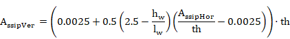
(ACI 349-01 11.10.9.4)
However, there is no need to assign the vertical direction for any axis. Therefore, the shear reinforcement would support the condition ahead:
![]()
(ACI 349-01 11.10.9.2)
The shear criteria are calculated as:
![]()
![]()
Another criteria is caluculated so as to compare the obtained reinforcement quantity with the minimum required:
Once again it is necessary to draw a distinction in case that one of the axis has been determined as the vertical one, due to the formulation to apply in the CRT_3.

In its horizontal direction

In the designed vertical direction
(# is the direction of the shell, X or Y)
Only if any axis has been established as vertical, the CRT_3 would be obtained from the equation ahead:

Therefore, the validity shear criterion is defined as follows:
![]()
These values
are stored for all elements in the CivilFEM results file as the parameters ![]() and
and ![]() .
.
If the strength provided by concrete is null and the shear reinforcement is not defined in the shell vertex, then Vn=0, and the criterion CRT_1 will be set equal to 2100.
If the shear reinforcement is not defined in the shell vertex, then the criterion CRT_3 is set equal to 2100.
The f·Vn value is stored in the CivilFEM results file as the parameter VPHI_# (# is the direction of the shell, X or Y).
13.16.2.4 In-plane shear criterion – Seismic loads
The nominal shear strength (Vn) is the sum of the concrete and shear reinforcement components:
![]()
But also limited by:
![]()
(ACI 349-01 21.6.5.3)
where Acv is the area of concrete.
![]()
The shell vertex will be valid for shear if the following conditions are satisfied:
![]()
![]()
(ACI 349-01 21.6.5.2)
![]()
![]()
(ACI 349-01 21.6.5.6)
Where f is the strength reduction factor (defined in ~CHKCON command).
On another note, as detailed in the ACI code, there is also a possibility to assign the X or Y axis as the vertical one.
In case that an
axis would be determined as the vertical one, ![]() would change due to the new
would change due to the new ![]() equation:
equation:
![]()
![]()
![]()
Where ![]() is a coefficient which variations depends on the
is a coefficient which variations depends on the ![]() ratio.
ratio.
![]() values, in different situations, would be:
values, in different situations, would be:
![]()
![]()
![]()
(In the last case, ![]() would be obtained interpolating linearly between 2 and 3)
would be obtained interpolating linearly between 2 and 3)
The existence of a vertical axis implies that reinforcements in those directions would follow the expressions ahead:
For defining the horizontal shear reinforcement, next condition has to be supported:
![]()
(ACI 349-01 11.10.9.2)
On the other hand, vertical shear reinforcement will be sustained by the next function:
(ACI 349-01 11.10.9.4)
However, there is no need to assign the vertical direction for any axis. Therefore, the shear reinforcement would support the condition ahead:
![]()
(ACI 349-01 11.10.9.2)
The shear criteria are calculated as:
![]()
Without vertical axis dependency
![]()
With vertical axis dependency
![]()
Another criteria is caluculated so as to compare the obtained reinforcement quantity with the minimum required:
Once again it is necessary to draw a distinction in case that one of the axis has been determined as the vertical one, due to the formulation to apply in the CRT_3.
In its horizontal direction
In the designed vertical direction
(# is the direction of the shell, X or Y)
Only if any axis has been established as vertical, the CRT_3 would be obtained from the equation ahead:
Therefore, the validity shear criterion is defined as follows:
![]()
These values
are stored for all elements in the CivilFEM results file as the parameters ![]() and
and![]() .
.
In case the strength provided by concrete is null and the shear reinforcement is not defined in the shell vertex, then Vn=0, and the criterion CRT_1 is set equal to 2100.
If shear reinforcement is not defined in the shell vertex, then the criterion CRT_3 is set equal to 2100.
The f·Vn value is stored in the CivilFEM results file as the parameter VPHI_# (# is the direction of the shell, X or Y).
13.16.3 In-Plane Shear Design for Walls
13.16.3.1 Shear strength provided by concrete
For sections subject to an axial compressive force, the shear strength provided by concrete (Vc) is calculated by:
![]()
![]()
(ACI 349-01 11.10.4 and 11.10.5)
Where:
![]() square root of specified compressive strength of
concrete, in psi (always taken as less than 100 psi).
square root of specified compressive strength of
concrete, in psi (always taken as less than 100 psi).
If the section is subjected to a tensile force such that the tensile stress is less than 500 psi:
![]()
![]()
(ACI 349-01 11.10.5, 11.3.2.3)
If the shell is subjected to a tensile force so that the tensile stress exceeds 500 psi, it is assumed Vc=0.
The calculated result for each element is stored in the CivilFEM results file as the parameter VC (# is the direction of the shell, X or Y):
VC_# Shear strength provided by concrete.
![]()
13.16.3.2 Required reinforcement contribution
The shell must satisfy the following condition to resist the shear force:
![]()
(ACI 349-01 11-1 and 11-2)
Where f is the strength reduction factor (defined in ~DIMCON command).
Required shear strength of the reinforcement:
![]()
The calculated result for each element is stored in the CivilFEM results file as the parameter VS (# is the direction of the shell, X or Y):
VS_# Shear strength provided by reinforcement.
![]()
13.16.3.3 Required reinforcement – Non seismic loads
The reinforcement amount is obtained by inserting the value of Vs, determined above, into the following equation:
![]()
![]()
![]()
(ACI 349-01 11.10.4 Eqn: 11-33)
On another note, as detailed in the ACI code, there is also a possibility to assign the X or Y axis as the vertical one. This implies that reinforcements in those directions would follow the expressions ahead:
For defining the horizontal shear reinforcement, next condition has to be supported:
![]()
(ACI 349-01 11.10.9.2)
Therefore:
![]()
for the horizontal direction.
On the other hand, vertical shear reinforcement will be sustained by the next function:
(ACI 349-01 11.10.9.4)
Therefore:

for the vertical direction.
However, there is no need to assign the vertical direction for any axis. Therefore, the shear reinforcement would support the condition ahead:

(ACI 349-01 11.10.9.2)
The area of the designed reinforcement per unit length is stored in the CivilFEM results file as:
![]()
![]()
Also, the following condition must be satisfied:
![]()
![]()
(ACI 349-01 11.10.3 and 11.10.4)
This criterion is calculated as:

(# is the direction of the shell, X or Y)
If CRT_2_# is greater than 1.0, the condition will not be satisfied, and therefore, the element will not be designed. ASSIP_# will be set to 2100 and the element will be labeled as not designed.
Another criterion is calculated so as to compare the obtained reinforcement quantity with the minimum required:
Once again it is necessary to draw a distinction in case that one of the axis has been determined as the vertical one, due to the formulation to apply in the CRT_3.
In its horizontal direction
In the designed vertical direction
(# is the direction of the shell, X or Y)
Only if any axis has been established as vertical, the CRT_3 would be obtained from the equation ahead:
13.16.3.4 Required reinforcement – Seismic loads
The shell vertex will be valid for shear if the following conditions are satisfied:
![]()
(ACI 349-01 Eqn: 11-1 and 11-2)
with
![]()
![]()
![]()
(ACI 349-01 Eqn: 11-33)
and
![]()
where Acv is the area of concrete
![]()
On another note, as detailed in the ACI code, there is also a possibility to assign the X or Y axis as the vertical one.
In case that an
axis would be determined as the vertical one, ![]() would change due to the new
would change due to the new ![]() equation:
equation:
![]()
![]()
![]()
Where ![]() is a coefficient which variations depends on the
is a coefficient which variations depends on the ![]() ratio.
ratio.
![]() values, in different situations, would be:
values, in different situations, would be:
![]()
![]()
![]()
(In the last case, ![]() would be obtained interpolating linearly between 2 and 3)
would be obtained interpolating linearly between 2 and 3)
For defining the horizontal shear reinforcement, next condition has to be supported:
![]()
(ACI 349-01 11.10.9.2)
Therefore:

for the horizontal direction.
On the other hand, vertical shear reinforcement will be sustained by the next function:
(ACI 349-01 11.10.9.4)
Therefore:

for the vertical direction.
However, there is no need to assign the vertical direction for any axis. Therefore, the reinforcement amount is the maximum value that satisfies both expressions:

The area of the designed reinforcement per unit length is stored in the CivilFEM results file as:
![]()
![]()
Also, the following condition must be satisfied:
![]()
![]()
(ACI 349-01 21.6.5.6)
This criterion is calculated as:

(# is the direction of the shell, X or Y)
If CRT_2_# is greater than 1.0, the condition will not be satisfied, and therefore, the element will not be designed. ASSIP_# will then be set to 2100 and the element will be labeled as not designed.
Another criterion is calculated so as to compare the obtained reinforcement quantity with the minimum required:
Once again it is necessary to draw a distinction in case that one of the axis has been determined as the vertical one, due to the formulation to apply in the CRT_3.
In its horizontal direction
In the designed vertical direction
(# is the direction of the shell, X or Y)
Only if any axis has been established as vertical, the CRT_3 would be obtained from the equation ahead:
13.16.4 In-Plane Shear Checking for Slabs (Seismic Loads)
13.16.4.1 In plane shear criterion
The nominal shear strength (Vn) is limited by:
![]()
(ACI 349-01 21.6.5.2)
Where Acv is the area of concrete:
![]()
The shell vertex will be valid for shear if the following conditions are satisfied:
![]()
(ACI 349-01 21.6.5.2)
![]()
![]()
(ACI 349-01 21.6.5.6)
![]()
(ACI 349-01 21.6.2.1, 7.12.2)
![]()
(ACI 349-01 7.12.3)
![]() parameter is the tensile concrete force,
while for the
parameter is the tensile concrete force,
while for the ![]() coefficient, the 60% of the specified
coefficient, the 60% of the specified ![]() value is calculated. The equal or bigger values than 72 inches for
thickness, will not require a minimum reinforcement quantity. Moreover, in the
7.12.3 formulation, the
value is calculated. The equal or bigger values than 72 inches for
thickness, will not require a minimum reinforcement quantity. Moreover, in the
7.12.3 formulation, the ![]() value cannot be higher than the
value cannot be higher than the ![]() value.
value.
Where f is the strength reduction factor (defined in ~CHKCON command).
The shear criterion is calculated as:
![]()
![]()
For demonstrating if the minimum quantity of reinforcement has been taking into account, the CRT_3_# is described as ahead:
![]()

(# is the direction of the shell, X or Y)
Therefore, the validity shear criterion is defined as follows:
![]()
These values
are stored for each element in the CivilFEM results file as the parameters ![]() and
and ![]() .
.
If the strength provided by concrete is null and shear reinforcement is not defined in the shell vertex, then Vn=0, and the criterion CRT_1 is set equal to 2100.
If shear reinforcement is not defined in the shell vertex, then the criterion CRT_3 is set equal to 2100.
The f·Vn value is stored in the CivilFEM results file as the parameter VPHI_# (# is the direction of the shell, X or Y).
13.16.5 In-Plane Shear Design for Slabs (Seismic Loads)
13.16.5.1 Required reinforcement
The shell vertex will be valid for shear if the following condition is satisfied:
![]()
(ACI 349-01 21.6.5.2)
where Acv is the area of concrete:
![]()
The reinforcement amount has a minimum requirement of:
![]()
(ACI 349-01 21.6.2.1, 7.12.2)
![]()
(ACI 349-01 7.12.3)
![]() parameter is the tensile concrete force,
while for the
parameter is the tensile concrete force,
while for the ![]() coefficient, the 60% of the specified
coefficient, the 60% of the specified ![]() value is calculated. The equal or bigger values than 72 inches for
thickness, will not require a minimum reinforcement quantity. Moreover, in the
7.12.3 formulation, the
value is calculated. The equal or bigger values than 72 inches for
thickness, will not require a minimum reinforcement quantity. Moreover, in the
7.12.3 formulation, the ![]() value cannot be higher than the
value cannot be higher than the ![]() value.
value.
Therefore the reinforcement amount is the minimum value that satisfies the following expressions for both X and Y directions:

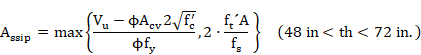
The area of the designed reinforcement per unit length is stored in the CivilFEM results file as:
![]()
![]()
Also, the following condition must be satisfied:
![]()
![]()
(ACI 349-01 21.6.5.6)
This criterion is calculated as:
(# is the direction of the shell, X or Y)
If CRT_2_# is greater than 1.0, the condition above will not be satisfied and therefore the element cannot be designed. ASSIP_# will be set to 2100 and the element will be labeled as not designed.
To determine if a minimum reinforcement amount has been defined, the CRT_3_# criterion is defined as:
![]()
(# is the direction of the shell, X or Y)
13.17 Check and Design for In-plane Shear Loadings according to ACI 349-13
13.17.1 Required Input Data
Shear checking or design according to ACI 349 requires the parameters described below. The formulas listed in this section utilize U.S. (British) units: inch (in), pound (lb), and second (s).
7. Material strength properties. This data is obtained from the material properties assigned to each active shell vertex, (see ~CFMP command). These material properties must be defined prior to check and design. The required properties are:
f’c specified compressive strength of concrete.
fy specified yield strength of reinforcement.
![]() modification factor for lightweight concrete.
modification factor for lightweight concrete.
8. Shell vertex data:
th thickness of the shell vertex (~SHLRNF command - THK).
Data concerning reinforcements of the shell vertex must be included within CivilFEM database. (See ~SHLRNF and ~SHLIPSH commands). Required properties are:
9. Shell vertex reinforcement data.
c bending reinforcement mechanical cover (~SHLRNF command -MC).
Ass the area of bending reinforcement per unit length. This parameter is used for checking(~SHLRNF command ASSXT, ASSXB, ASSYT, ASSYB).
10. Shell vertex shear reinforcement data.
AssipX, AssipX area of in plane shear reinforcement per unit of length in each direction of the shell. These parameters are used for checking (parameter ASSIPX and ASSIPY of ~SHLIPSH command).
11. Shell vertex internal forces. The shear force that acts on the vertex as well as the concomitant membrane force are obtained from the CivilFEM results file (.RCV). For each direction of the shell vertex:
Force Description
Vu Design in plane shear force
Nu Membrane force (positive for compression) perpendicular to Vu
12. Type of check/design. In-plane shear check/design according to ACI 349-01 is divided into the three following types:
· Walls with non-seismic loads. Covers chapter 14 of ACI 349-01 for walls.
· Walls with seismic loads. Covers chapters 14 and 21 of ACI 349-01 for walls.
· Slabs with seismic loads. Covers chapter 21 of ACI 349-01 for slabs.
Checks and designs may be defined in ~CHKCON and ~DIMCON commands, respectively.
13.17.2 In-Plane Shear Checking for Walls
13.17.2.1 Shear strength provided by concrete
For sections subjected to an axial compressive force, the shear strength provided by concrete (Vc) is calculated as:
![]()
![]()
(ACI 349-13)
Where:
![]() square root of specified compressive strength of concrete,
in psi (always taken less than 100 psi).
square root of specified compressive strength of concrete,
in psi (always taken less than 100 psi).
If the section is subjected to a tensile force such that the tensile stress is less than 500 psi then,
![]()
![]()
(ACI 349-13)
If the shell is subjected to a tensile force such that the tensile stress exceeds 500 psi, it is assumed Vc=0.
The calculation result for all elements is stored in the CivilFEM results file as the parameter VC (# is the direction of the shell, X or Y):
VC_# Shear strength provided by concrete.
![]()
13.17.2.2 Shear strength provided by shear reinforcement
The strength provided by shear reinforcement (Vs) is calculated with the following expression:
![]()
![]()
![]()
(ACI 349-13)
The calculated result for all elements is stored in the CivilFEM results file as the parameter VS (# is the direction of the shell, X or Y):
VS_# Shear strength provided by reinforcement.
![]()
13.17.2.3 In-plane shear criterion – Non seismic loads
The nominal shear strength (Vn) is the sum of the concrete and shear reinforcement components calculated previously:
![]()
The shell vertex will be valid for shear if the following conditions are satisfied:
![]()
(ACI 349-13)
![]()
![]()
(ACI 349-13)
Where f is the strength reduction factor (defined in ~CHKCON command).
On another note, as detailed in the ACI code, there is also a possibility to assign the X or Y axis as the vertical one. This implies that reinforcements in those directions would follow the expressions ahead:
For defining the horizontal shear reinforcement, next condition has to be supported:
![]()
(ACI 349-01 11.10.9.2)
On the other hand, vertical shear reinforcement will be sustained by the next function:
(ACI 349-01 11.10.9.4)
However, there is no need to assign the vertical direction for any axis. Therefore, the shear reinforcement would support the condition ahead:
![]()
(ACI 349-01 11.10.9.2)
The shear criteria are calculated as:
![]()
![]()
Another criterion is calculated so as to compare the obtained reinforcement quantity with the minimum required:
Once again it is necessary to draw a distinction in case that one of the axis has been determined as the vertical one, due to the formulation to apply in the CRT_3.
In its horizontal direction
In the designed vertical direction
(# is the direction of the shell, X or Y)
Only if any axis has been established as vertical, the CRT_3 would be obtained from the equation ahead:
Therefore, the validity shear criterion is defined as follows:
![]()
These values
are stored for all elements in the CivilFEM results file as the parameters ![]() and
and ![]() .
.
If the strength provided by concrete is null and the shear reinforcement is not defined in the shell vertex, then Vn=0, and the criterion CRT_1 will be set equal to 2100.
If the shear reinforcement is not defined in the shell vertex, then the criterion CRT_3 is set equal to 2100.
The f·Vn value is stored in the CivilFEM results file as the parameter VPHI_# (# is the direction of the shell, X or Y).
13.17.2.4 In-plane shear criterion – Seismic loads
The nominal shear strength (Vn) is the sum of the concrete and shear reinforcement components:
![]()
But also limited by:
![]()
(ACI 349-13)
where Acv is the area of concrete
![]()
The shell vertex will be valid for shear if the following conditions are satisfied:
![]()
![]()
(ACI 349-13)
![]()
![]()
(ACI 349-13)
![]()
(ACI 349-13)
Where f is the strength reduction factor (defined in ~CHKCON command).
On another note, as detailed in the ACI code, there is also a possibility to assign the X or Y axis as the vertical one.
In case that an
axis would be determined as the vertical one, ![]() would change due to the new
would change due to the new ![]() equation:
equation:
![]()
![]()
![]()
Where ![]() is a coefficient which variations depends on the
is a coefficient which variations depends on the ![]() ratio.
ratio.
![]() values, in different situations, would be:
values, in different situations, would be:
![]()
![]()
![]()
(In the last case, ![]() would be obtained interpolating linearly between 2 and 3)
would be obtained interpolating linearly between 2 and 3)
For defining the horizontal shear reinforcement, next condition has to be supported:
![]()
(ACI 349-01 11.10.9.2)
On the other hand, vertical shear reinforcement will be sustained by the next function:
(ACI 349-01 11.10.9.4)
However, there is no need to assign the vertical direction for any axis. Therefore, the shear reinforcement would support the condition ahead:
![]()
(ACI 349-01 11.10.9.2)
The shear criteria is calculated as:
![]()
Without vertical axis dependency
![]()
With vertical axis dependency
![]()
Another criterion is calculated so as to compare the obtained reinforcement quantity with the minimum required:
Once again it is necessary to draw a distinction in case that one of the axis has been determined as the vertical one, due to the formulation to apply in the CRT_3.
In its horizontal direction
In the designed vertical direction
(# is the direction of the shell, X or Y)
Only if any axis has been established as vertical, the CRT_3 would be obtained from the equation ahead:
Therefore, the validity shear criterion is defined as follows:
![]()
These values
are stored for all elements in the CivilFEM results file as the parameters ![]() and
and![]() .
.
In case the strength provided by concrete is null and the shear reinforcement is not defined in the shell vertex, then Vn=0, and the criterion CRT_1 is set equal to 2100.
If shear reinforcement is not defined in the shell vertex, then the criterion CRT_3 is set equal to 2100.
The f·Vn value is stored in the CivilFEM results file as the parameter VPHI_# (# is the direction of the shell, X or Y).
13.17.3 In-Plane Shear Design for Walls
13.17.3.1 Shear strength provided by concrete
For sections subject to an axial compressive force, the shear strength provided by concrete (Vc) is calculated by:
![]()
![]()
(ACI 349-13)
Where:
![]() square root of specified compressive strength of
concrete, in psi (always taken as less than 100 psi).
square root of specified compressive strength of
concrete, in psi (always taken as less than 100 psi).
If the section is subjected to a tensile force such that the tensile stress is less than 500 psi:
![]()
![]()
(ACI 349-13)
If the shell is subjected to a tensile force so that the tensile stress exceeds 500 psi, it is assumed Vc=0.
The calculated result for each element is stored in the CivilFEM results file as the parameter VC (# is the direction of the shell, X or Y):
VC_# Shear strength provided by concrete.
![]()
13.17.3.2 Required reinforcement contribution
The shell must satisfy the following condition to resist the shear force:
![]()
(ACI 349-13)
Where f is the strength reduction factor (defined in ~DIMCON command).
Required shear strength of the reinforcement:
![]()
The calculated result for each element is stored in the CivilFEM results file as the parameter VS (# is the direction of the shell, X or Y):
VS_# Shear strength provided by reinforcement.
![]()
13.17.3.3 Required reinforcement – Non seismic loads
The reinforcement amount is obtained by inserting the value of Vs, determined above, into the following equation:
![]()
![]()
![]()
(ACI 349-13)
On another note, as detailed in the ACI code, there is also a possibility to assign the X or Y axis as the vertical one. This implies that reinforcements in those directions would follow the expressions ahead:
For defining the horizontal shear reinforcement, next condition has to be supported:
![]()
(ACI 349-01 11.10.9.2)
On the other hand, vertical shear reinforcement will be sustained by the next function:
for the horizontal direction.
(ACI 349-01 11.10.9.4)
Therefore:

for the vertical direction.
However, there is no need to assign the vertical direction for any axis. Therefore, the shear reinforcement would support the condition ahead:
![]()
(ACI 349-01 11.10.9.2)
The area of the designed reinforcement per unit length is stored in the CivilFEM results file as:
![]()
![]()
Also, the following condition must be satisfied:
![]()
![]()
(ACI 349-13)
This criterion is calculated as:
(# is the direction of the shell, X or Y)
If CRT_2_# is greater than 1.0, the condition will not be satisfied, and therefore, the element will not be designed. ASSIP_# will be set to 2100 and the element will be labeled as not designed.
Another criterion is calculated so as to compare the obtained reinforcement quantity with the minimum required:
Once again it is necessary to draw a distinction in case that one of the axis has been determined as the vertical one, due to the formulation to apply in the CRT_3.
In its horizontal direction
In the designed vertical direction
(# is the direction of the shell, X or Y)
Only if any axis has been established as vertical, the CRT_3 would be obtained from the equation ahead:
13.17.3.4 Required reinforcement – Seismic loads
The shell vertex will be valid for shear if the following conditions are satisfied:
![]()
(ACI 349-13)
with
![]()
![]()
![]()
(ACI 349-13)
and
![]()
(ACI 349-13)
where Acv is the area of concrete:
![]()
But also limited by:
![]()
(ACI 349-13)
where Acv is the area of concrete
![]()
On another note, as detailed in the ACI code, there is also a possibility to assign the X or Y axis as the vertical one.
In case that an
axis would be determined as the vertical one, ![]() would change due to the new
would change due to the new ![]() equation:
equation:
![]()
![]()
![]()
Where ![]() is a coefficient which variations depends on the
is a coefficient which variations depends on the ![]() ratio.
ratio.
![]() values, in different situations, would be:
values, in different situations, would be:
![]()
![]()
![]()
(In the last case, ![]() would be obtained interpolating linearly between 2 and 3)
would be obtained interpolating linearly between 2 and 3)
For defining the horizontal shear reinforcement, next condition has to be supported:
![]()
(ACI 349-01 11.10.9.2)
Therefore:
for the horizontal direction.
On the other hand, vertical shear reinforcement will be sustained by the next function:
(ACI 349-01 11.10.9.4)
Therefore:
for the vertical direction.
However, there is no need to assign the vertical direction for any axis. Therefore, the reinforcement amount is the maximum value that satisfies both expressions:
The area of the designed reinforcement per unit length is stored in the CivilFEM results file as:
![]()
![]()
Also, the following condition must be satisfied:
![]()
![]()
(ACI 349-13)
This criterion is calculated as:
(# is the direction of the shell, X or Y)
If CRT_2_# is greater than 1.0, the condition will not be satisfied, and therefore, the element will not be designed. ASSIP_# will then be set to 2100 and the element will be labeled as not designed.
Another criterion is calculated so as to compare the obtained reinforcement quantity with the minimum required:
Once again it is necessary to draw a distinction in case that one of the axis has been determined as the vertical one, due to the formulation to apply in the CRT_3.
In its horizontal direction
In the designed vertical direction
(# is the direction of the shell, X or Y)
Only if any axis has been established as vertical, the CRT_3 would be obtained from the equation ahead:
13.17.4 In-Plane Shear Checking for Slabs (Seismic Loads)
13.17.4.1 In plane shear criterion
The nominal shear strength (Vn) is limited by:
![]()
(ACI 349-13)
Where Acv is the area of concrete:
![]()
The shell vertex will be valid for shear if the following conditions are satisfied:
![]()
(ACI 349-13)
![]()
![]()
(ACI 349-13)
![]()
(ACI 349-13)
![]()
(ACI 349-01 7.12.3)
![]() parameter is the tensile concrete force,
while for the
parameter is the tensile concrete force,
while for the ![]() coefficient, the 60% of the specified
coefficient, the 60% of the specified ![]() value is calculated. The equal or bigger values than 72 inches for
thickness, will not require a minimum reinforcement quantity. Moreover, in the
7.12.3 formulation, the
value is calculated. The equal or bigger values than 72 inches for
thickness, will not require a minimum reinforcement quantity. Moreover, in the
7.12.3 formulation, the ![]() value cannot be higher than the
value cannot be higher than the ![]() value.
value.
Where f is the strength reduction factor (defined in ~CHKCON command).
The shear criteria are calculated as:
![]()
![]()
To determine if a minimum reinforcement amount has been defined, the CRT_3_# criterion is defined as:
![]()
(# is the direction of the shell, X or Y)
Therefore, the validity shear criterion is defined as follows:
![]()
These values
are stored for each element in the CivilFEM results file as the parameters ![]() and
and ![]() .
.
If the strength provided by concrete is null and shear reinforcement is not defined in the shell vertex, then Vn=0, and the criterion CRT_1 is set equal to 2100.
If shear reinforcement is not defined in the shell vertex, then the criterion CRT_3 is set equal to 2100.
The f·Vn value is stored in the CivilFEM results file as the parameter VPHI_# (# is the direction of the shell, X or Y).
13.17.5 In-Plane Shear Design for Slabs (Seismic Loads)
13.17.5.1 Required reinforcement
The shell vertex will be valid for shear if the following condition is satisfied:
![]()
(ACI 349-13)
where Acv is the area of concrete:
![]()
The reinforcement amount has a minimum requirement of:
![]()
(ACI 349-13)
![]()
(ACI 349-01 7.12.3)
![]() es la
tensión a tracción del hormigón, mientras que para
es la
tensión a tracción del hormigón, mientras que para ![]() , se
cogerá el 60% del
, se
cogerá el 60% del ![]() especificado,
mientras que para valores de espesores de 72 in o más, no se requiere cuantía
mínima de refuerzo. Además, en la fórmula 7.12.3,
especificado,
mientras que para valores de espesores de 72 in o más, no se requiere cuantía
mínima de refuerzo. Además, en la fórmula 7.12.3, ![]() no
podrá exceder el valor de
no
podrá exceder el valor de ![]() .
.
Therefore the reinforcement amount is the minimum value that satisfies the following expressions for both X and Y directions:
The area of the designed reinforcement per unit length is stored in the CivilFEM results file as:
![]()
![]()
Also, the following condition must be satisfied:
![]()
![]()
(ACI 349-13)
This criterion is calculated as:
(# is the direction of the shell, X or Y)
If CRT_2_# is greater than 1.0, the condition above will not be satisfied and therefore the element cannot be designed. ASSIP_# will be set to 2100 and the element will be labeled as not designed.
To determine if a minimum reinforcement amount has been defined, the CRT_3_# criterion is defined as:
![]()
13.18 Check and Design according to ACI 359-04 (Reinforced Concrete)
13.18.1 Introduction
This code evaluation is based upon the 2004 ASME BOILER & PRESSURE VESSEL CODE SECTION III Division 2, also known as ACI 359-04, Article CC-3000 DESIGN.
13.18.2 Required Input Data
Checking and design according to ACI 359-04 requires the parameters described below:
1. Material strength properties. Material properties are assigned to each active shell vertex, (see ~CFMP command). These material properties must be defined prior to checking and design. The required properties are:
f’c specified compressive strength of concrete.
fy specified yield strength of reinforcement.
2. Shell vertex data:
th thickness of the shell vertex (~SHLRNF command - THK).
Data concerning reinforcements of the shell vertex must be included within the
CivilFEM database. (See ~SHLRNF ,~SHLSHR and ~SHLIPSH commands). Required properties are:
3. Shell vertex reinforcement data.
c bending reinforcement mechanical cover (~SHLRNF command -MC).
Ass the area of bending reinforcement per unit length. This parameter is used for checking (~SHLRNF command ASSXT, ASSXB, ASSYT, ASSYB).
4. Shell vertex shear reinforcement data.
Ass area of shear reinforcement per unit area. This parameter is used for checking (parameter ASSOP of ~SHLSHR command).
AssipX, AssipY area of tangential shear reinforcement per unit length in each direction of the shell. These parameters are used for checking (parameters ASSIPX and ASSIPY of ~SHLIPSH command).
The shear reinforcement ratio may also be obtained with the following data:
AssX, AssY area of shear reinforcement per unit area in each direction of the shell. (parameters ASSOPX and ASSOPY of ~SHLSHR command)
sx, sy spacing of the stirrups in each direction of the shell, (parameters SXOP and SYOP of ~SHLSHR command).
f diameter of bars in mm (parameter PHIOP of ~SHLSHR command).
Nx, Ny number of stirrups per unit length in each direction of the shell (parameters NXOP and NYOP of ~SHLSHR command).
5. Shell vertex internal forces. Shear forces on the vertex as concomitant membrane force are obtained from the CivilFEM results file (.RCV) for each direction of the shell vertex:
Force Description
Vu Design shear force
Nu Axial force (positive for compression).
Mu Bending Moment
13.18.3 Directions
ACI 359-04 code specifies hoop and meridional directions. The user must identify the element X axis with the meridional direction and Y axes with the hoop direction or vice versa.
13.18.4 Design Types
With CivilFEM it is possible to accomplish the following checking and analysis types defined in Article CC-3000:
|
Radial Shear |
CC-3421.4, CC-3431.3, CC-3521.2, CC-3522, CC-3422, CC-3432 |
|
Tangential Shear |
CC-3421.5, CC-3521.1, CC-3522, CC-3431.3, CC-3422, CC-3432 |
|
Flexure and axial force |
CC-3421.1, CC-3421.2, CC-3422, CC-3431.1, CC-3431.2, CC-3432, CC-3510, CC-3511, CC-3522 |
13.18.5 Radial shear check
Radial shear is a transverse shear and is similar to shear in beam analysis. Radial shear is composed of contributions to the strength from concrete and reinforcing steel.
13.18.5.1 Factored loads
13.18.5.1.1 Applied shear stress vu
The nominal (applied) shear stress is computed as:
![]()
(ACI 359-04 CC-3521.2.1(Eqn.16))
Where:
Vu = Ny or Nx = applied radial shear (both directions are checked independently and a reinforcement amount is obtained for each direction).
b = bw = unit length
d= th – c =Shell thickness minus the mechanical cover of the bending reinforcement.
13.18.5.1.2 Required concrete contribution
The nominal shear shall not exceed the minimum value from the table:
|
|
EQUATION |
EXPRESSION |
APPLICABILITY CONDITION |
|
a |
1 |
|
|
|
2 |
|
|
|
|
3 |
|
|
|
|
b |
4 |
|
Section subjected to membrane compression (Nu >0).
If |
|
5 |
|
Section subjected to membrane
compression |
|
|
6 |
|
Section subjected to membrane
compression |
|
|
c |
7 |
|
Section subjected to membrane
tension |


(ACI 359-04 CC-3421.4.1(a),(b),(c))
In equation 7, when ![]() , vc is taken as vu.
, vc is taken as vu.
Where:
![]() ratio of bonded
reinforcement. As is the additional of bending reinforcement (top
and bottom) and in-plane shear reinforcement
ratio of bonded
reinforcement. As is the additional of bending reinforcement (top
and bottom) and in-plane shear reinforcement
Nu shell membrane force Tx or Ty based on the direction being designed.
13.18.5.1.3 Required reinforcement contribution
The required area of reinforcing is calculated as:
![]() (CC-3521.2.3)
(CC-3521.2.3)
Instead of calculating an area of reinforcement, CivilFEM calculates a reinforcement ratio with the units of area per unit area. To obtain this value, the width (b) and spacing (s) in the equation above will be set to one, such that:

The required shear reinforcement ratio is determined as follows:
· If the nominal shear stress is less than the allowable concrete shear stress, then shear reinforcing will not be required: If vu ≤ vc, then Av = zero.
· If the nominal shear stress exceeds the allowable concrete shear stress, then shear reinforcing must be provided to resist the additional shear.
Radial shear reinforcement assigned to the shell vertex (Assop) is compared to the calculated reinforcement Av using the criterion:
![]()
The nominal (applied) shear load must be less than the limit established by the code.
Therefore, if:
![]() (CC-3521.2.3(f))
(CC-3521.2.3(f))
Then CRT = 2100, indicating the radial shear stress in the shear reinforcement does not meet criteria and the section needs to be redesigned.
13.18.5.2 Service loads - Primary forces only
13.18.5.2.1 Applied shear stress v
The nominal (applied) shear stress is computed as:
![]()
(ACI 359-04 CC-3522(a))
Where:
V = Ny or Nx = applied radial shear (both directions are checked independently and reinforcement amount is obtained for each direction).
b = bw = unit length.
d= th – c =Shell thickness minus the mechanical cover of the bending reinforcement.
13.18.5.2.2 Required concrete contribution
The required
concrete contribution will be 67% (CC-3431.3(a)(2)) of the value provided by the factored loads. The value of vc
when shell vertex is subject to membrane tension will not be reduced below ![]() (CC-3431.3(a)(1)).
(CC-3431.3(a)(1)).
13.18.5.2.3 Required reinforcement contribution
The required area of reinforcement is calculated as:
![]() (CC-3521.2.3
and CC-3522(b))
(CC-3521.2.3
and CC-3522(b))
Instead of calculating an area of reinforcement, CivilFEM calculates a reinforcement ratio with units of area per unit area. To obtain this value, the width (b) and spacing (s) in the equation above will be set to one, such that:

The necessary shear reinforcement ratio is determined as follows.
· If the nominal shear stress is less than the allowable concrete shear stress, then shear reinforcing is not required: If v ≤ vc then Av = zero
· If the nominal shear stress exceeds the allowable concrete shear stress, then shear reinforcing must be provided to carry the additional shear.
Radial shear reinforcement assigned to the shell vertex (Assop) is compared to the calculated reinforcement Av using the criterion:
![]()
The nominal (applied) shear load must be less than the limit established by the code.
Therefore, if:
![]() (CC-3521.2.3(f), CC-3432.3(a)),
(CC-3521.2.3(f), CC-3432.3(a)),
Then CRT = 2100, indicating the radial shear stress in the shear reinforcement does not meet criteria and the section needs to be redesigned.
13.18.5.3 Service loads - Primary plus Secondary loads except the Structural Integrity Test (SIT)
13.18.5.3.1 Applied shear stress v
The nominal (applied) shear stress is computed as:
![]()
(ACI 359-04 CC-3522(a))
Where:
V = Ny or Nx = applied radial shear (both directions are checked independently and a reinforcement amount is obtained for each direction).
b = bw = unit length.
d= th – c = Shell thickness less the bending reinforcement mechanical cover.
13.18.5.3.2 Required concrete contribution
The required
concrete contribution will be 67% (CC-3431.3(a)(2)) of the value provided by the factored loads. The value of vc
when shell vertex is subject to membrane tension will not be reduced below ![]() (CC-3431.3(a)(1)).
(CC-3431.3(a)(1)).
13.18.5.3.3 Required reinforcement contribution
The required area of reinforcement is calculated as:
![]() (CC-3521.2.3
and CC-3522(b))
(CC-3521.2.3
and CC-3522(b))
Instead of calculating an area of reinforcement, CivilFEM calculates a reinforcement ratio with units of area per area. To obtain this value, the width (b) and spacing (s) in the equation above will be set to one, such that:

The necessary shear reinforcement ratio is determined as follows:
· If the nominal shear stress is less than the allowable concrete shear stress, shear reinforcing will not be required: If v ≤ vc then Av = zero.
· If the nominal shear stress exceeds the allowable concrete shear stress, the shear reinforcing must be provided to carry the additional stress.
Radial shear reinforcement assigned to the shell vertex (Assop) is compared to the calculated reinforcement Av using the criterion:
![]()
The nominal (applied) shear load must be less than the limit established by the code.
Therefore, if:
![]() (CC-3521.2.3, CC-3432.3(a)),
(CC-3521.2.3, CC-3432.3(a)),
Then CRT = 2100, indicating that the radial shear stress in the shear reinforcement does not meet criteria and the section needs to be redesigned.
13.18.5.4 Service loads – Primary or Primary plus Secondary loads including the Structural Integrity Test (SIT)
13.18.5.4.1 Applied shear stress v
The nominal (applied) shear stress is computed as:
![]()
(ACI 359-04 CC-3522(a))
Where:
V = Ny or Nx = applied radial shear (both directions are checked independently and a reinforcement amount is obtained for each direction).
b = bw = unit length.
d= th – c =Shell thickness minus the mechanical cover of the bending reinforcement.
13.18.5.4.2 Required concrete contribution
The required
concrete contribution will be 67% (CC-3431.3(a)(3)) of the value provided by the factored loads. The value of vc
when shell vertex is subject to membrane tension will not be reduced below ![]() (CC-3431.3(a)(1)).
(CC-3431.3(a)(1)).
13.18.5.4.3 Required reinforcement contribution
The required area of reinforcing is calculated as:
 (CC-3521.2.3 and CC-3522(b))
In place of calculating an area of reinforcement, CivilFEM calculates a reinforcement ratio with units of area per unit area. To obtain this value the width (b) and spacing (s) in the equation above will be set to one, such that:

The necessary shear reinforcement ratio is determined as follows.
· If the nominal shear stress is less than the allowable concrete shear stress, shear reinforcing will not be required: If v ≤ vc then Av = zero.
· If the nominal shear stress exceeds the allowable concrete shear stress, then shear reinforcing must be provided to resist the additional shear.
Radial shear reinforcement assigned to the shell vertex (Assop) is compared to the calculated reinforcement Av using the criterion:
![]()
The nominal (applied) shear load must be less than the limit established by the code.
Therefore, if:
![]() (CC-3521.2.3(f), CC-3432.3(a))
(CC-3521.2.3(f), CC-3432.3(a))
The criterion CRT = 2100, indicating the radial shear stress in the shear reinforcement does not meet criteria and the section needs to be redesigned.
13.18.5.5 Results
Checking results are stored in the CivilFEM results file:
|
VC_X |
Allowable shear stress in concrete, X direction. |
|
VS_X |
Minimum shear strength to be provided by shear reinforcement, X direction. |
|
VU_X |
Nominal shear stress, X direction. |
|
CRT_X |
Criterion for X direction |
|
VC_Y |
Allowable shear stress in concrete, Y direction. |
|
VS_Y |
Minimum shear strength to be provided by shear reinforcement, Y direction. |
|
VU_Y |
Nominal shear stress, Y direction. |
|
CRT_Y |
Criterion for Y direction. |
|
CRT_TOT |
Total criterion. |
The total criterion is the ratio between the total required reinforcement and the reinforcement assigned to the shell vertex. If the reinforcement has been defined independently for each direction, the total criterion is the maximum of CRT_X and CRT_Y. If the reinforcement has been defined as a global amount, the criterion is defined for this amount as CRT_TOT = CRT_X = CRT_Y.
13.18.6 Radial Shear Design
The maximum shear strength and the shear strength concrete are determined separately. The required reinforcing shear resistance is defined as the difference between the two. The required reinforcement is calculated to provide the necessary resistance.
13.18.6.1 Factored loads
13.18.6.1.1 Applied shear stress vu
The nominal (applied) shear stress is computed as:
![]()
(ACI 359-04 CC-3521.2.1(Eqn.16))
Where:
Vu = Ny or Nx = applied radial shear (both directions are checked independently and a reinforcement amount is obtained for each direction).
b = bw = unit length.
d= th – c =Shell thickness minus the mechanical cover of the bending reinforcement.
13.18.6.1.2 Required concrete contribution
The nominal shear shall not exceed the minimum value of the following values:
|
|
EQUATION |
EXPRESSION |
APPLICABILITY CONDITION |
|
a |
1 |
|
|
|
2 |
|
|
|
|
3 |
|
|
|
|
b |
4 |
|
Section subjected to membrane compression (Nu >0).
If |
|
5 |
|
Section subjected to membrane
compression |
|
|
6 |
|
Section subjected to membrane
compression |
|
|
c |
7 |
|
Section subjected to membrane
tension |
(ACI 359-04 CC-3421.4.1(a),(b),(c))
In equation 7, when ![]() , vc is taken as vu.
, vc is taken as vu.
Where:
![]() ratio of
bonded reinforcement. As is the additional bending reinforcement
(top and bottom) and in-plane shear reinforcement.
ratio of
bonded reinforcement. As is the additional bending reinforcement
(top and bottom) and in-plane shear reinforcement.
Nu shell membrane force Tx or Ty based on the direction being designed.
13.18.6.1.3 Required reinforcement contribution
The required area of reinforcement is calculated as:

(CC-3521.2.3)
Instead of calculating an area of reinforcement, CivilFEM calculates a reinforcement ratio with units of area per unit area. To obtain this value, the width (b) and spacing (s) in the equation above will be set to one, such that:
The necessary shear reinforcement ratio is determined as follows:
· If the nominal shear stress is less than the allowable concrete shear stress, shear reinforcing will not be required: If vu ≤ vc then Av = zero
· If the nominal shear stress exceeds the allowable concrete shear stress, then shear reinforcing must be provided to resist the additional stress.
The nominal (applied) shear load must be less than the limit established by the code:
Therefore, if:
![]() (CC-3521.2.3(f))
(CC-3521.2.3(f))
Then Av = 2100, indicating the radial shear stress in the shear reinforcement does not meet criteria and the section needs to be redesigned.
13.18.6.2 Service loads - Primary forces only
13.18.6.2.1 Applied shear stress v
The nominal (applied) shear stress is computed as:
![]()
(ACI 359-04 CC-3522(a))
Where:
V = Ny or Nx = applied radial shear (both directions are checked independently and reinforcement amount is obtained for each direction).
b = bw = unit length.
d= th – c =Shell thickness minus the mechanical cover of the bending reinforcement.
13.18.6.2.2 Required concrete contribution
The required concrete contribution will be 50% (CC-3431.3(a)) of
the value provided by the factored loads. The value of vc when the
shell vertex is subject to membrane tension will not be reduced below ![]() (CC-3431.3(a)(1)).
(CC-3431.3(a)(1)).
13.18.6.2.3 Required reinforcement contribution
The required area of reinforcing is calculated as:
![]() (CC-3521.2.3
and CC-3522(b))
(CC-3521.2.3
and CC-3522(b))
Instead of calculating an area of reinforcement, CivilFEM calculates a reinforcement ratio with units of area per unit area. To obtain this value, the width (b) and spacing (s) in the equation above will be set as one, such that:
The necessary shear reinforcement ratio is determined as follows.
· If the nominal shear stress is less than the allowable concrete shear stress, shear reinforcing will not be required: If v ≤ vc then Av = zero
· If the nominal shear stress exceeds the allowable concrete shear stress, then shear reinforcing must be provided to resist the additional stress.
The nominal (applied) shear load must be less than the limit established by the code.
Therefore, if:
![]() (CC-3521.2.3(f), CC-3431.3(a))
(CC-3521.2.3(f), CC-3431.3(a))
Then Av = 2100, indicating the radial shear stress in the shear reinforcement does not meet criteria and the section needs to be redesigned.
13.18.6.3 Service loads - Primary plus Secondary forces except during the Structural Integrity Test (SIT)
13.18.6.3.1 Applied shear stress v
The nominal (applied) shear stress is computed as:
![]()
(ACI 359-04 CC-3522(a))
Where:
V = Ny or Nx = applied radial shear (both directions are checked independently and reinforcement amount is obtained for each direction).
b = bw = unit length.
d= th – c =Shell thickness minus the mechanical cover of the bending reinforcement.
13.18.6.3.2 Required concrete contribution
The required
concrete contribution will be 67% (CC-3431.3(a)(2)) of the value provided by the factored loads. The value of vc
when shell vertex is subject to membrane tension will not be reduced below ![]() (CC-3431.3(a)(1)).
(CC-3431.3(a)(1)).
13.18.6.3.3 Required reinforcement contribution
The required area of reinforcing is calculated as:
![]() (CC-3521.2.3
and CC-3522(b))
(CC-3521.2.3
and CC-3522(b))
Instead of calculating an area of reinforcement, CivilFEM calculates a reinforcement ratio with units of area per unit area. To obtain this value, the width (b) and spacing (s) in the preceding equation will be set to one, such that:
The necessary shear reinforcement ratio is determined as follows.
· If the nominal shear stress is less than the allowable concrete shear stress, shear reinforcing will not be required: If v ≤ vc then Av = zero
· If the nominal shear stress exceeds the allowable concrete shear stress, then shear reinforcing must be provided to resist the additional stress.
The nominal (applied) shear load must be less than the limit established by the code. Therefore, if:
![]() (CC-3521.2.3(f), CC-3431.3(a))
(CC-3521.2.3(f), CC-3431.3(a))
Then Av = 2100, indicating the radial shear stress in the shear reinforcement does not meet criteria and the section needs to be redesigned.
13.18.6.4 Service loads – Primary or Primary plus secondary loads including the Structural Integrity Test (SIT)
13.18.6.4.1 Applied shear stress v
The nominal (applied) shear stress is computed as:
![]()
(ACI 359-04 CC-3522(a))
Where:
V = Ny or Nx = applied radial shear (both directions are checked independently and reinforcement amount is obtained for each direction).
b = bw = unit length.
d= th – c =Shell thickness minus the mechanical cover of the bending reinforcement.
13.18.6.4.2 Required concrete contribution
The required
concrete contribution will be 67% (CC-3431.3(a)(3)) of the value provided by the factored loads. The value of vc
when shell vertex is subject to membrane tension will not be reduced below ![]() (CC-3431.3(a)(1)).
(CC-3431.3(a)(1)).
13.18.6.4.3 Required reinforcement contribution
The required area of reinforcing is calculated as:
![]() (CC-3521.2.3
and CC-3522(b))
(CC-3521.2.3
and CC-3522(b))
Instead of calculating an area of reinforcement, CivilFEM calculates a reinforcement ratio with units of area per unit area. To obtain this value, the width (b) and spacing (s) in the equation above will be set to one, such that:

The necessary shear reinforcement ratio is determined as follows.
· If the nominal shear stress is less than the allowable concrete shear stress, shear reinforcing will not be required: If v ≤ vc then Av = zero.
· If the nominal shear stress exceeds the allowable concrete shear stress, then shear reinforcing must be provided to resist the additional stress.
The nominal (applied) shear load must be less that the limit established by the code. Therefore, if:
![]() (CC-3521.2.3(f), CC-3431.3(a))
(CC-3521.2.3(f), CC-3431.3(a))
Then Av = 2100, indicating the radial shear stress in the shear reinforcement does not meet criteria and the section needs to be redesigned.
13.18.6.5 Results
Design results are stored in the CivilFEM results file:
|
VC_X |
Allowable shear stress in concrete, X direction. |
|
VS_X |
Shear strength provided by shear reinforcement, X direction. |
|
VU_X |
Nominal shear stress, X direction. |
|
ASSH_X |
Shear reinforcement ratio, X direction. |
|
VC_Y |
Allowable shear stress in concrete, Y direction. |
|
VS_Y |
Shear strength provided by shear reinforcement, Y direction. |
|
VU_Y |
Nominal shear stress, Y direction. |
|
ASSH_Y |
Shear reinforcement ratio, Y direction. |
|
ASSH |
Area per unit area of shear reinforcement. |
|
DSG_CRT |
Total design criterion. |
ASSH is the total reinforcement ratio and the sum of ASSH_X and ASSH_Y.
DSG_CRT is the criterion that would be obtained in checking if the reinforcement is the one provided by the design process.
13.18.7 Tangential shear check
Tangential shear is a membrane shear in the plane of shell element.
13.18.7.1 Factored Loads
13.18.7.1.1 Required concrete contribution
For reinforced (non-prestressed) concrete, no tangential shear strength shall be provided by the concrete:
![]()
(CC-3421.5.1)
13.18.7.1.2 Required reinforcement contribution
Required areas of reinforcement are computed as follows:


(ACI 359-04 CC-3521.1.1(Eqn.12),(Eqn.13))
where:
|
Ash |
Area of bonded reinforcement in the hoop direction (area/length). |
|
Asm |
Area of bonded reinforcement in the meridional direction (area/length). |
|
Asi |
Area of bonded reinforcement in one direction of inclined bars (area/length). |
|
Nh, Nm |
Membrane forces in the hoop and meridional direction respectively due to pressure, prestress, and dead load. |
|
Nhl, Nml |
Membrane forces in the hoop and meridional direction, respectively, from lateral load such as earthquake, wind or tornado load. Always positive. |
If the lateral loads are not specified, Nhl and Nml will be zero. If the simplified method is specified in ~CHKCON command (VAL5 = -1), they will be obtained by subtracting the loads due to prestressing, pressure and dead loads from the total loads.
Provided reinforcement Assip is compared to the required reinforcement, calculated using CC-3521.1.1, equations (12) and (13), with the following factors:
![]()
Tangential shear strength provided by the orthogonal reinforcement Vso:
![]()
(ACI 359-04 CC-3521.1.1 (Eqn.14))
This value shall not be greater than ![]()
Where:
- Vu is the maximum applied tangential shear Txy.
- t overall thickness of member.
Since inclined reinforcement is not considered by CivilFEM, the following equation shall be satisfied:
![]()
This limit is considered with the CivilFEM orthogonal reinforcement shear strength criterion as follows:
![]()
Additionally, if the tangential shear strength limit specified by RG 1.136 (SRP 3.8.1, Section II.5.A) is considered (set by the user in ~CHKCON command), the following criterion will be:

The orthogonal reinforcement strength criterion will be the larger of the two values. If the above criteria are greater than one, inclined reinforcement will be necessary.
NOTE: If the orthogonal reinforcement shear strength limit is not satisfied, the reinforcing amounts Asm+Asi and Ash+Asi (equations 12 or 13 from CC-3521.1.1) will be calculated and compared to the reinforcement assigned to the shell vertex. However, the orthogonal reinforcement criterion CRT_ASO will be greater than 1.
13.18.7.2 Service Loads - Primary Forces Only
13.18.7.2.1 Required concrete contribution
For reinforced (non-prestressed) concrete, no tangential shear strength shall be provided by the concrete:
![]()
(CC-3421.5.1)
13.18.7.2.2 Required reinforcement contribution
Required areas of reinforcement are computed as follows:


(ACI 359-04 CC-3521.1.1(Eqn.12),(Eqn.13) and CC-3522(c))
where:
|
Ash |
Area of bonded reinforcement in the hoop direction (area/length). |
|
Asm |
Area of bonded reinforcement in the meridional direction (area/length). |
|
Asi |
Area of bonded reinforcement in one direction of the inclined bars (area/length). |
|
Nh, Nm |
Membrane forces in the hoop and meridional direction, respectively, due to pressure, prestress, and dead load. |
|
Nhl, Nml |
Membrane forces in the hoop and meridional direction, respectively, from lateral load such as earthquake, wind or tornado load. Always will be positive. |
If the lateral loads are not specified, Nhl and Nml will be zero. If the simplified method is specified in the ~CHKCON command (VAL5 = -1), they will be obtained by subtracting the loads due to prestressing, pressure and dead loads from the total loads.
Provided reinforcement Assip is compared to the required reinforcement, calculated using CC-3521.1.1, equations (12) and (13), with the following factors:
![]()
Tangential shear strength provided by the orthogonal reinforcement Vso:
![]()
(ACI 359-04 CC-3522(e) and CC-3522(c))
However, Vso shall not be
greater than ![]()
Where:
- Vu maximum applied tangential shear Txy.
- t overall thickness of member.
Since inclined reinforcement is not considered by CivilFEM, the following equation shall be satisfied:
![]()
This limit is considered with the CivilFEM orthogonal reinforcement shear strength criterion as follows:

Additionally, if the tangential shear strength limit specified by RG 1.136 (SRP 3.8.1, Section II.5.A) is considered (set by the user in ~CHKCON command), the following criterion will be:
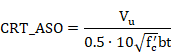
The orthogonal reinforcement strength criterion will be the larger of the two values. If the above criteria are greater than one, inclined reinforcement will be necessary.
NOTE: If the orthogonal reinforcement shear strength limit is not satisfied, the reinforcing amounts Asm+Asi and Ash+Asi (equations 12 or 13 from CC-3521.1.1) will be calculated and are compared to the reinforcement assigned to the shell vertex. However, the orthogonal reinforcement criterion CRT_ASO will be greater than 1.
13.18.7.3 Service Loads - Primary Plus Secondary Loads, Except the Structural Integrity Test (SIT)
13.18.7.3.1 Required concrete contribution
For reinforced (non-prestressed) concrete, no tangential shear strength shall be provided by the concrete:
![]()
(CC-3421.5.1)
13.18.7.3.2 Required reinforcement contribution
Required areas of reinforcement are computed as follows:


(ACI 359-04 CC-3521.1.1(Eqn.12), (Eqn.13) and CC-3522(c))
where:
|
Ash |
Area of bonded reinforcement in the hoop direction (area/length). |
|
Asm |
Area of bonded reinforcement in the meridional direction (area/length). |
|
Asi |
Area of bonded reinforcement in one direction of inclined bars (area/length). |
|
Nh, Nm |
Membrane forces in the hoop and meridional direction respectively due to pressure, prestress, and dead load. |
|
Nhl, Nml |
Membrane forces in the hoop and meridional direction, respectively, from a lateral load such as earthquake, wind or tornado load. Always positive. |
If the lateral loads are not specified, Nhl and Nml will be zero. If the simplified method is specified in ~CHKCON command (VAL5 = -1), they will be obtained by subtracting the loads due to prestressing, pressure and dead loads from the total loads.
The defined reinforcement Assip is compared to the required reinforcement, calculated using CC-3521.1.1, equations (12) and (13), with the following factors:
![]()
Tangential shear strength provided by the orthogonal reinforcement Vso:
![]()
(ACI 359-04 CC-3522)
This value shall not be greater than 0.5·0.2 f’cbt.
Where:
- Vu maximum applied tangential shear Txy.
- t overall thickness of member.
Since inclined reinforcement is not considered by CivilFEM, the following equation shall be satisfied:
![]()
This limit is considered by CivilFEM with the orthogonal reinforcement shear strength criterion as follows”
![]()
Additionally, if the tangential shear strength limit specified by RG 1.136 (SRP 3.8.1, Section II.5.A) is considered (set by the user in ~CHKCON command), the following criterion will be:

The orthogonal reinforcement strength criterion is the larger of the two values. If the above criteria are greater than one, inclined reinforcement will be necessary.
NOTE: If the orthogonal reinforcement shear strength limit is not satisfied, the reinforcement amounts Asm+Asi and Ash+Asi (equations 12 or 13 from CC-3521.1.1) are calculated and compared to the reinforcement assigned to the shell vertex. However, the orthogonal reinforcement criterion CRT_ASO is greater than 1.
13.18.7.4 Service loads - Primary plus Secondary loads including the Structural Integrity Test (SIT)
13.18.7.4.1 Required concrete contribution
For reinforced (non-prestressed) concrete, no tangential shear strength shall be provided by the concrete:
![]()
(CC-3421.5.1)
13.18.7.4.2 Required reinforcement contribution
Required areas of reinforcement are computed as follows:
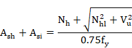

(ACI 359-04 CC-3521.1.1(Eqn.12),(Eqn.13) and CC-3522(c))
where:
|
Ash |
Area of bonded reinforcement in the hoop direction (area/length). |
|
Asm |
Area of bonded reinforcement in the meridional direction (area/length). |
|
Asi |
Area of bonded reinforcement in one direction of inclined bars (area/length). |
|
Nh, Nm |
Membrane forces in the hoop and meridional direction, respectively, due to pressure, prestress, and dead load. |
|
Nhl, Nml |
Membrane forces in the hoop and meridional direction, respectively, from a lateral load such as earthquake, wind or tornado load. Always positive. |
If the lateral loads are not specified, Nhl and Nml will be zero. If the simplified method is specified in ~CHKCON command (VAL5 = -1), they will be obtained by subtracting the loads due to prestressing, pressure and dead loads from the total loads.
The defined reinforcement Assip is compared to the required reinforcement, calculated using CC-3521.1.1, equations (12) and (13), with the following factors:
CRT_AS = (Asi+As)/Assip
Tangential shear strength provided by the orthogonal reinforcement Vso:
![]()
(ACI 359-04 CC-3522)
This value shall not be greater than![]() .
.
Where:
- Vu maximum applied tangential shear Txy.
- t overall thickness of member.
Since inclined reinforcement is not considered by CivilFEM, the following equation shall be satisfied:
![]()
This limit is considered by CivilFEM with the orthogonal reinforcement shear strength criterion as follows:
![]()
Additionally, if the tangential shear strength limit specified by RG 1.136 (SRP 3.8.1, Section II.5.A) is considered (set by the user in ~CHKCON command), the following criterion will be:
![]()
The orthogonal reinforcement strength criterion will be the larger of the two values. If the above criteria are greater than one, inclined reinforcement will be necessary.
NOTE: If the orthogonal reinforcement shear strength limit is not satisfied, the reinforcement amounts Asm+Asi and Ash+Asi (equations 12 or 13 from CC-3521.1.1) are calculated and compared to the reinforcement assigned to the shell vertex. However, the orthogonal reinforcement criterion CRT_ASO will be greater than 1.
13.18.7.5 Results
Checking results are stored in the CivilFEM results file:
|
VC |
Shear strength provided by concrete. |
|
CRT_ASX |
Reinforcement factor for X direction. |
|
CRT_ASY |
Reinforcement factor for Y direction. |
|
CRT_ASO |
Orthogonal reinforcement strength limit criterion. |
|
CRT_TOT |
Total criterion |
The reinforcement factor is the ratio between the required reinforcement and the reinforcement assigned to the shell vertex.
The total criterion is the maximum value of the reinforcement factor for each direction of the shell.
13.18.8 Tangential Shear Design
Tangential shear is a membrane shear in the plane of element shell.
13.18.8.1 Factored Loads
13.18.8.1.1 Required concrete contribution
For reinforced (non-prestressed) concrete, no tangential shear strength shall be provided by the concrete:
![]()
(CC-3421.5.1)
13.18.8.1.2 Required reinforcement contribution
Required areas of reinforcement are computed as follows:
(ACI 359-04 CC-3521.1.1(Eqn.12), (Eqn.13))
where:
|
Ash |
Area of bonded reinforcement in the hoop direction (area/length). |
|
Asm |
Area of bonded reinforcement in the meridional direction (area/length). |
|
Asi |
Area of bonded reinforcement in one direction of inclined bars (area/length). |
|
Nh, Nm |
Membrane forces in the hoop and meridional direction, respectively, due to pressure, prestress, and dead load. |
|
Nhl, Nml |
Membrane forces in the hoop and meridional direction, respectively, from a lateral load such as earthquake, wind or tornado load. Always positive. |
If the lateral loads are not specified, Nhl and Nml will be zero. If the simplified method is specified in ~DIMCON command (VAL5 = -1), they will be obtained by subtracting the loads due to prestressing, pressure and dead loads from the total loads.
Tangential shear strength provided by the orthogonal reinforcement Vso:
![]()
(ACI 359-04 CC-3521.1.1(Eqn.14))
This value shall not be greater than ![]() .
.
Where:
- Vu maximum applied tangential shear Txy.
- t overall thickness of member.
Since inclined reinforcement is not considered by CivilFEM, the following equation shall be satisfied:
![]()
This limit is considered by CivilFEM with the orthogonal reinforcement shear strength criterion as follows
![]()
Additionally, if the tangential shear strength limit specified by RG 1.136 (SRP 3.8.1, Section II.5.A) is considered (set by the user in ~DIMCON command), the following criterion will be:
The orthogonal reinforcement strength criterion is the larger of the two values. If the above criteria are greater than one, inclined reinforcement will be necessary.
NOTE: If the orthogonal reinforcement shear strength limit is not satisfied, the reinforcing amounts Asm+Asi and Ash+Asi (equations 12 or 13 from CC-3521.1.1) will be calculated and compared to the reinforcement assigned to the shell vertex. However, the orthogonal reinforcement criterion CRT_ASO will be greater than 1.
13.18.8.2 Service Loads - Primary Forces Only
13.18.8.2.1 Required concrete contribution
For reinforced (non-prestressed) concrete, no tangential shear strength shall be provided by the concrete:
![]()
(CC-3421.5.1)
13.18.8.2.2 Required reinforcement contribution
Required areas of reinforcement are computed as follows:
(ACI 359-04 CC-3521.1.1(Eqn.12),(Eqn.13) and CC-3522(c))
where:
|
Ash |
Area of bonded reinforcement in the hoop direction (area/length). |
|
Asm |
Area of bonded reinforcement in the meridional direction (area/length). |
|
Asi |
Area of bonded reinforcement in one direction of inclined bars (area/length). |
|
Nh, Nm |
Membrane forces in the hoop and meridional direction, respectively, due to pressure, prestress, and dead load. |
|
Nhl, Nml |
Membrane forces in the hoop and meridional direction, respectively, from a lateral load such as earthquake, wind or tornado load. Always positive. |
If the lateral loads are not specified, Nhl and Nml will be zero. If the simplified method is specified in ~DIMCON command (VAL5 = -1), they will be obtained by subtracting the loads due to prestressing, pressure and dead loads from the total loads.
Tangential shear strength provided by the orthogonal reinforcement Vso:
![]()
(ACI 359-04 CC-3522(e) and CC-3522(c))
This value shall not be greater than ![]() .
.
Where:
- Vu is the maximum applied tangential shear Txy.
- t overall thickness of member.
Since inclined reinforcement is not considered by CivilFEM, the following equation shall be satisfied:
![]()
This limit is considered with the CivilFEM orthogonal reinforcement shear strength criterion as follows:
![]()
Additionally, if the tangential shear strength limit specified by RG 1.136 (SRP 3.8.1, Section II.5.A) is considered (set by the user in ~DIMCON command), the following criterion will be:
The orthogonal reinforcement strength criterion is the larger of the two values. If the above criteria are greater than one, inclined reinforcement will be necessary.
NOTE: If the orthogonal reinforcement shear strength limit is not satisfied, the reinforcing amounts Asm+Asi and Ash+Asi (equations 12 or 13 from CC-3521.1.1) are calculated and compared to the reinforcement assigned to the shell vertex. However, the orthogonal reinforcement criterion CRT_ASO will be greater than 1.
13.18.8.3 Service loads - Primary Plus Secondary Loads, Except the Structural Integrity Test (SIT)
13.18.8.3.1 Required concrete contribution
For reinforced (non-prestressed) concrete, no tangential shear strength shall be provided by the concrete:
![]()
(CC-3421.5.1)
13.18.8.3.2 Required reinforcement contribution
Required areas of reinforcement are computed as follows:
(ACI 359-04 CC-3521.1.1(Eqn.12),(Eqn.13) and CC-3522(c))
where:
|
Ash |
Area of bonded reinforcement in the hoop direction (area/length). |
|
Asm |
Area of bonded reinforcement in the meridional direction (area/length). |
|
Asi |
Area of bonded reinforcement in one direction of inclined bars (area/length). |
|
Nh, Nm |
Membrane forces in the hoop and meridional direction, respectively, due to pressure, prestress, and dead load. |
|
Nhl, Nml |
Membrane forces in the hoop and meridional direction, respectively, from a lateral load such as earthquake, wind or tornado load. Always positive. |
If the lateral loads are not specified, Nhl and Nml will be zero. If the simplified method is specified in ~DIMCON command (VAL5 = -1), they will be obtained by subtracting the loads due to prestressing, pressure and dead loads from the total loads.
Tangential shear strength provided by the orthogonal reinforcement Vso:
![]()
(ACI 359-04 CC-3522)
This value shall not be greater than ![]() .
.
Where:
- Vu maximum applied tangential shear Txy.
- t overall thickness of member.
Since inclined reinforcement is not considered by CivilFEM, the following equation shall be satisfied:
![]()
This limit is considered with the CivilFEM orthogonal reinforcement shear strength criterion as follows:
![]()
Additionally, if the tangential shear strength limit specified by RG 1.136 (SRP 3.8.1, Section II.5.A) is considered (set by the user in ~DIMCON command), the following criterion will be:
The orthogonal reinforcement strength criterion is the larger of the two values. If the above criteria are greater than one, inclined reinforcement will be required.
NOTE: If the orthogonal reinforcement shear strength limit is not satisfied, the reinforcing amounts Asm+Asi and Ash+Asi (equations 12 or 13 from CC-3521.1.1) will be calculated and compared to the reinforcement assigned to the shell vertex. However, the orthogonal reinforcement criterion CRT_ASO will be greater than 1.
13.18.8.4 Service loads - Primary Plus Secondary Loads Including the Structural Integrity Test (SIT)
13.18.8.4.1 Required concrete contribution
For reinforced (non-prestressed) concrete, no tangential shear strength shall be provided by the concrete:
![]()
(CC-3421.5.1)
13.18.8.4.2 Required reinforcement contribution
Required areas of reinforcement are computed as follows:

(ACI 359-04 CC-3521.1.1(Eqn.12),(Eqn.13) and CC-3522(c))
where:
|
Ash |
Area of bonded reinforcement in the hoop direction (area/length). |
|
Asm |
Area of bonded reinforcement in the meridional direction (area/length). |
|
Asi |
Area of bonded reinforcement in one direction of inclined bars (area/length). |
|
Nh, Nm |
Membrane forces in the hoop and meridional direction, respectively, due to pressure, prestress, and dead load. |
|
Nhl, Nml |
Membrane forces in the hoop and meridional direction, respectively, from a lateral load such as earthquake, wind or tornado load. Always positive. |
If the lateral loads are not specified, Nhl and Nml will be zero. If the simplified method is specified in ~DIMCON command (VAL5 = -1), they will be obtained by subtracting the loads due to prestressing, pressure and dead loads from the total loads.
Tangential shear strength provided by the orthogonal reinforcement Vso:
![]()
(ACI 359-04 CC-3522)
This value shall not be greater than ![]() .
.
Where:
- Vu maximum applied tangential shear Txy.
- t overall thickness of member.
Since inclined reinforcement is not considered by CivilFEM, the following equation shall be satisfied:
![]()
This limit is considered with the CivilFEM the orthogonal reinforcement shear strength criterion as follows
![]()
Additionally, if the tangential shear strength limit specified by RG 1.136 (SRP 3.8.1, Section II.5.A) is considered (set by the user in ~DIMCON command), the following criterion will be:
The orthogonal reinforcement strength criterion will be the larger of the two values. If the above criteria are greater than one, inclined reinforcement will be required.
NOTE: If the orthogonal reinforcement shear strength limit is not satisfied, the reinforcing amounts Asm+Asi and Ash+Asi (equations 12 or 13 from CC-3521.1.1) will be calculated and compared to the reinforcement assigned to the shell vertex. However, the orthogonal reinforcement criterion CRT_ASO will be greater than 1.
13.18.8.5 Results
Design results are stored in the CivilFEM results file:
|
VC |
Shear strength provided by concrete. |
|
ASX |
Reinforcement amount (area per unit length) for X direction. |
|
ASY |
Reinforcement amount (area per unit length) for Y direction. |
|
CRT_ASO |
Orthogonal reinforcement strength limit criterion. |
|
DSG_CRT |
Total design criterion |
DSG_CRT is the criterion that would be obtained in checking if the reinforcement is the one provided by the design process.
13.18.9 Flexure and axial check
Flexure and axial checking is performed using an interaction diagram to obtain the stress distribution of steel and concrete. This diagram is obtained from the materials' strengths for every end of the vertex in the X and Y direction and. Refer to sections 13.1.3 and 13.1.4 for additional information on the interaction diagrams.
13.18.9.1 Allowable Stresses for Factored Loads
13.18.9.1.1 Concrete
13.18.9.1.1.1 Compression
The compression normal stresses shall not exceed the following limits (Table CC-3421-1):
|
|
ALLOWABLE STRESSES |
|
|
|
MEMBRANE |
MEMBRANE+FLEXURE(2) |
|
PRIMARY |
|
|
|
PRIMARY+SECONDARY(1) |
|
|
(1) The primary portion of this calculated stress shall not exceed the allowable stress applicable when primary stress acts alone.
(2) Membrane checking and flexure are independent; therefore, both must be computed.
(3) The maximum allowable primary-plus-secondary membrane and bending compressive stress of 0.85f’c shall not exceed a limiting strain of 0.002. The most restrictive limit will be used.
The membrane limit is used to calculate the pure compression point on the interaction diagram by setting the C Pivot of the diagram (refer to Chapter 11-A.3.1).
13.18.9.1.1.2 Tension
Concrete tensile strength will not be considered (CC-3421.2).
13.18.9.1.2 Reinforcing Steel
The design yield strength, fy, shall not exceed 60,000 psi (CC-3422.1). However, this limit can be modified using the checking command (~CHKCON).
The allowable stress for load resistance shall not exceed the following (CC-3422.1 and CC-3422.2):
|
|
ALLOWABLE STRESSES |
|
|
|
TENSION |
COMPRESSION |
|
PRIMARY |
|
|
|
PRIMARY+SECONDARY |
|
|
In general, stresses in the steel shall not exceed the allowable stress specified above. However, strains may exceed the yield strength when the reinforcement is used with concrete that requires larger strains for developing full capacity.
This is equivalent to a steel stress-strain diagram with the limit for the inclined branch of the allowable stress specified above.
13.18.9.2 Allowable Stresses for Service Loads
13.18.9.2.1 Concrete
13.18.9.2.1.1 Compression
The compression normal stresses shall not exceed the following limits (Table CC-3431-1):
|
|
ALLOWABLE STRESSES |
|
|
|
MEMBRANE |
MEMBRANE+FLEXURE(2) |
|
PRIMARY |
|
|
|
PRIMARY+SECONDARY(1) |
|
|
|
PRIMARY+SIT (3) |
|
|
|
PRIMARY+SECONDARY+SIT(3) |
|
|
|
PRIMARY+SIT (RG1.90) (4) |
|
|
|
PRIMARY+SECONDARY+SIT (RG1.90) (4) |
|
|
(1) The primary portion of this calculated stress shall not exceed the allowable stress applicable when primary stress acts alone.
(2) The membrane checking and flexure are independent; therefore, both must be computed.
(3) Structural Integrity Test
(4) Regulatory Guide 1.90
The membrane limit is used to calculate the pure compression point on the interaction diagram by setting the C Pivot of the diagram (refer to Chapter 11-A.3.1).
13.18.9.2.1.2 Tension
Concrete tensile strength will not be considered (CC-3421.2).
13.18.9.2.2 Reinforcing Steel
The design yield strength, fy, shall not exceed 60,000 psi (CC-3422.1). However, this limit can be modified using the checking command (~CHKCON).
The allowable stress for load resistance shall not exceed the following (CC-3432.1 and CC-3432.2).
|
|
ALLOWABLE STRESSES |
|
|
|
TENSION |
COMPRESSION |
|
PRIMARY |
|
|
|
PRIMARY+SECONDARY |
|
|
|
PRIMARY+SIT (1) |
|
|
|
PRIMARY+SECONDARY+SIT(1) |
|
|
|
PRIMARY+SIT (RG1.90) (2) |
|
|
|
PRIMARY+SECONDARY+SIT (RG1.90) (2) |
|
|
(1) Structural Integrity Test: Stress limits may be increased by 50% when the temporary pressure loads during the test condition are combined with primary or primary plus secondary loads
(2) Regulatory Guide 1.90: Section III, Division 2, of the ASME Code allows an increase of the allowable stress in tensile reinforcement under a test condition. However, if such testing is to be performed a number of times during the life of the structure, it is advised not to use this allowance to avoid gradual propagation of cracks.
In general, stresses in the steel shall not exceed the allowable stress specified above. However, strains may exceed the yield strength when the reinforcement is used with concrete that requires larger strains for developing full capacity.
This is equivalent to a steel stress-strain diagram with the limit for the inclined branch of the allowable stress specified above.
13.18.9.3 Results
Figure 13.13‑1 Determination of the homothetic strain state
This criterion is defined as the ratio between two distances, d1 and d2. The distance d1 is from the “center” of the diagram (point A of Figure 13.13‑1) to the point which represents the acting forces and moments (point P of Figure 13.13‑1). Distance d2 is between the center and the point which represents the homothetic ultimate forces and moments (point B).
If the criterion is less than 1.00, this indicates the forces and moments acting on the section are below the ultimate strength and the section is safe. On the contrary, for criterion higher than 1.00, the section will be considered as under-reinforced.
Note: Refer to chapter 11-A.3: Interaction diagram for additional information.
Checking results are stored in the CivilFEM results file:
|
CRT_X |
Criterion for X direction |
|
CRT_Y |
Criterion for Y direction. |
|
CRT_TOT |
Total criterion. |
CRT_TOT is the maximum value of CRT_X and CRT_Y.
13.18.10 Flexure and axial design
Flexure and axial design is performed using an interaction diagram to obtain the stress distribution of steel and concrete. This diagram is obtained from the materials' strengths for the vertex in the X and Y direction. Refer to Sections 13.1.3 and 13.1.4 for additional information on interaction diagrams.
For each direction, CivilFEM will obtain the reinforcement amount that provides a criterion of 1.00 (see flexure and axial checking) with a tolerance of 1%.
13.18.10.1 Allowable Stresses for Factored loads
13.18.10.1.1 Concrete
13.18.10.1.1.1 Compression
The compression normal stresses shall not exceed the following limits (Table CC-3421-1):
|
|
ALLOWABLE STRESSES |
|
|
|
MEMBRANE |
MEMBRANE+FLEXURE(2) |
|
PRIMARY |
|
|
|
PRIMARY+SECONDARY(1) |
|
|
(1) The primary portion of this calculated stress shall not exceed the allowable stress applicable when primary stress acts alone.
(2) The membrane checking and flexure are independent; therefore, both must be computed.
(3) The maximum allowable primary-plus-secondary membrane and bending compressive stress of 0.85f’c shall not exceed a limiting strain of 0.002. The most restrictive limit will be used.
The membrane limit is used to calculate the pure compression point on the interaction diagram by setting the C Pivot of the diagram (refer to Chapter 11-A.3.1).
13.18.10.1.1.2 Tension
Concrete tensile strength will not be considered (CC-3421.2).
13.18.10.1.2 Reinforcing Steel
The design yield strength, fy, shall not exceed 60,000 psi (CC-3422.1). However, this limit can be modified using the design command (~DIMCON).
The allowable stress for load resistance shall not exceed the following (CC-3422.1 and CC-3422.2)
|
|
ALLOWABLE STRESSES |
|
|
|
TENSION |
COMPRESSION |
|
PRIMARY |
|
|
|
PRIMARY+SECONDARY |
|
|
In general, stresses in the steel shall not exceed the allowable stress specified above. However, strains may exceed the yield strength when the reinforcement is used with concrete that requires larger strains for developing full capacity.
This is equivalent to a steel stress-strain diagram with the limit for the inclined branch of the allowable stress specified above.
13.18.10.2 Allowable Stresses for Service Loads
13.18.10.2.1 Concrete
13.18.10.2.1.1 Compression
The compression normal stresses shall not exceed the following limits (Table CC-3431-1):
|
|
ALLOWABLE STRESSES |
|
|
|
MEMBRANE |
MEMBRANE+FLEXURE(2) |
|
PRIMARY |
|
|
|
PRIMARY+SECONDARY(1) |
|
|
|
PRIMARY+SIT (3) |
|
|
|
PRIMARY+SECONDARY+SIT(3) |
|
|
|
PRIMARY+SIT (RG1.90) (4) |
|
|
|
PRIMARY+SECONDARY+SIT (RG1.90) (4) |
|
|
(1) The primary portion of this calculated stress shall not exceed the allowable stress applicable when primary stress acts alone.
(2) The membrane checking and flexure are independent; therefore, both must be computed.
(3) Structural Integrity Test
(4) Regulatory Guide 1.90
The membrane limit is used to calculate the pure compression point on the interaction diagram by setting the C Pivot of the diagram (refer to Chapter 11-A.3.1).
13.18.10.2.1.2 Tension
Concrete tensile strength will not be considered (CC-3421.2).
13.18.10.2.2 Reinforcing Steel
The design yield strength, fy, shall not exceed 60,000 psi (CC-3422.1). However, this limit can be modified using the design command (~DIMCON).
The allowable stress for load resistance shall not exceed the following (CC-3432.1 and CC-3432.2).
|
|
ALLOWABLE STRESSES |
|
|
|
TENSION |
COMPRESSION |
|
PRIMARY |
|
|
|
PRIMARY+SECONDARY |
|
|
|
PRIMARY+SIT (1) |
|
|
|
PRIMARY+SECONDARY+SIT(1) |
|
|
|
PRIMARY+SIT (RG1.90) (2) |
|
|
|
PRIMARY+SECONDARY+SIT (RG1.90) (2) |
|
|
(1) Structural Integrity Test: Stress limits may be increased by 50% when the temporary pressure loads during the test condition are combined with primary or primary plus secondary loads.
(2) Regulatory Guide 1.90: Section III, Division 2, of the ASME Code allows an increase of the allowable stress in tensile reinforcement under a test condition. However, if such testing is to be performed a number of times during the life of the structure, it is advised not to use this allowance to avoid gradual propagation of cracks.
In general, stresses in the steel shall not exceed the allowable stress specified above. However, strains may exceed the yield strength when the reinforcement is used with concrete that requires larger strains for developing full capacity.
This is equivalent to a steel stress-strain diagram with the limit for the inclined branch of the allowable stress specified above.
13.18.10.3 Results
Design results are stored in the CivilFEM results file:
|
ASTX |
Reinforcement amount at X top. |
|
ASBX |
Reinforcement amount at X bottom. |
|
ASTY |
Reinforcement amount at Y top. |
|
ASBY |
Reinforcement amount at Y bottom. |
|
DSG_CRT |
Total criterion. |
13.18.11 Flexure, axial and shear design
This global design is composed of all of the design types described in the previous chapters: membrane and bending, tangential shear and radial shear design.
13.18.11.1 Procedure
The comments and explanations for radial shear design, tangential shear design, and flexure and axial design in chapters 13.13.6, 13.13.8, and 13.13.10 will also apply to this global design option.
For more information see ~DIMCON command (Lab2 = BEND_SHR).
Reinforcement material and mechanical cover must be defined in the corresponding shell vertex (bending reinforcement); see ~SHLRNF command.
Additionally, reinforcement material must be defined in the corresponding shell vertex for the following reinforcements:
- Shear reinforcement: see ~SHLSHR command.
- In-plane shear reinforcement: see ~SHLIPSH command.
13.18.11.2 Results
Design results summarize all previous design types and are stored in the CivilFEM results file:
|
ASTX |
Reinforcement amount at X top. |
|
ASBX |
Reinforcement amount at X bottom. |
|
ASTY |
Reinforcement amount at Y top. |
|
ASBY VC |
Reinforcement amount at Y bottom. Tangential shear strength provided by concrete. |
|
ASX |
Reinforcement amount for in plane shear, X direction. |
|
ASY |
Reinforcement amount for in plane shear, Y direction. |
|
CRT_ASO |
Orthogonal reinforcement limit criterion. |
|
VC_X |
Allowable radial shear stress in concrete, X direction. |
|
VS_X |
Shear strength provided by radial shear reinforcement, X direction. |
|
VU_X |
Nominal radial shear stress, X direction |
|
ASSH_X |
Area per unit length of radial shear reinforcement, X direction. |
|
VC_Y |
Allowable radial shear stress in concrete, Y direction. |
|
VS_Y |
Shear strength provided by radial shear reinforcement, Y direction. |
|
VU_Y |
Nominal radial shear stress, Y direction |
|
ASSH_Y |
Area per unit length of radial shear reinforcement, Y direction. |
|
ASSH |
Area per unit area of radial shear reinforcement. |
|
DSG_2D |
Bending plus axial design criterion. |
|
DSG_TSH |
Tangential shear design criterion. |
|
DSG_RSH |
Radial shear design criterion. |
|
DSG_CRT |
Total design criterion. |
13.19 Check and Design according to ACI 359-04 (Prestressed Concrete)
13.19.1 Introduction
General design is taken from 2004 ASME BOILER & PRESSURE VESSEL CODE SECTION III Division 2, also known as ACI 359-04, Article CC-3000 DESIGN.
All the equations are in U.S. Customary Units.
13.19.2 Required Input Data
Checking and design according to ACI 359-04 requires the parameters described below:
1. Material strength properties. Material properties are assigned to each active shell vertex, (see ~CFMP command). These material properties must be defined prior to checking and design. The required properties are:
f’c specified compressive strength of concrete.
fy specified yield strength of reinforcement.
2. Shell vertex data:
th thickness of the shell vertex (~SHLRNF command - THK).
Data concerning reinforcements of the shell vertex must be included within
CivilFEM database. (See ~SHLRNF ,~SHLSHR and ~SHLIPSH commands). Required properties are:
3. Shell vertex reinforcement data.
c bending reinforcement mechanical cover (~SHLRNF command -MC).
Ass area of bending reinforcement per unit length. This parameter is used for checking (~SHLRNF command ASSXT, ASSXB, ASSYT, ASSYB).
4. Shell vertex shear reinforcement data.
Ass area of shear reinforcement per unit area. This parameter is used for checking (parameter ASS of ~SHLSHR command).
AssipX, AssipY area of tangential shear reinforcement per unit length in each direction of the shell. These parameters are used for checking (parameters ASSIPX and ASSIPY of ~SHLIPSH command).
The shear reinforcement ratio may also be obtained with:
AssX, AssY area of shear reinforcement per unit area in each direction of the shell. (parameters ASSOPX and ASSOPY of ~SHLSHR command)
sx, sy spacing of the stirrups in each direction of the shell, (parameters SXOP and SYOP of ~SHLSHR command).
f diameter of bars in mm (parameter PHIOP of ~SHLSHR command).
Nx, Ny number of stirrups per unit length in each direction of the shell (parameters NXOP and NYOP of ~SHLSHR command).
5. Shell vertex internal forces. Shear forces on the vertex as concomitant membrane force are obtained from the CivilFEM results file (.RCV) for each direction of the shell vertex:
Force Description
Vu Design shear force
Nu Axial force (positive for compression).
Mu Bending Moment
13.19.3 Directions
The check and design procedures described below will be performed for each direction (X, Y) of the shell.
ACI 359-04 code specifies hoop and meridional directions. The user must identify the X axis of the element with the meridional direction and Y axis with the hoop direction or vice versa.
13.19.4 Design Types
With CivilFEM it is possible to accomplish the following checking and analysis types defined in Article CC-3000:
|
Radial Shear |
CC-3421.4, CC-3431.3, CC-3521.2, CC-3522, CC-3422, CC-3432 |
|
Tangential Shear |
CC-3421.5, CC-3521.1, CC-3522, CC-3431.3, CC-3422, CC-3432 |
|
Flexure and axial force |
CC-3421.1, CC-3421.2, CC3422, CC-3431.1, CC-3431.2, CC-3432, CC-3510, CC-3511, CC-3522 |
13.19.5 Radial shear check
Radial shear is a transverse shear, similar to shear in beam analysis. Radial shear strength is composed of contributions from the concrete and the reinforcing steel.
13.19.5.1 Factored Loads
13.19.5.1.1 Applied shear stress vu
The nominal (applied) shear stress is computed as:
![]()
(ACI 359-04 CC-3521.2.1(Eqn.16))
Where:
Vu = Ny or Nx = applied radial shear (both directions are checked independently and a reinforcement amount is obtained for each direction).
b = bw = unit length.
d= th – c ≥0.85h =Shell thickness minus the mechanical cover of the bending reinforcement.
13.19.5.1.2 Required concrete contribution
The allowable shear stress vc shall be less than vci or vcw, as calculated by:


(ACI 359-04 CC-3421.4.2(Eqn.8) ,(Eqn.9))
In these expressions:
- K depends on r in the following way:
|
|
K |
|
|
|
|
|
|
- Mcr is the moment necessary to cause cracking
![]()
- Coefficient n

- If Mcr – Mi is less than zero, it shall be considered as zero.
- The following definitions shall be used:
V = applied shear load at the section under consideration.
M = applied moment associated with the applied shear load.
Vi = existing shear loads at the section under consideration (positive if applied in the same direction as V).
Mi = existing moments associated with the existing shear loads (positive if applied in the same direction as the applied moments).
Mcr = moment necessary to cause cracking (always positive).
fpc = membrane stress, due to all loads, in the concrete at the centroid of the section where V is applied (positive if compressive).
I = Moment of inertia at the distance d/2 from the section investigated for shear, measured in the direction of decreasing moment.
yt = Distance from the centroidal axis of gross section, neglecting the reinforcement, to the extreme tension fiber.
r = As/bd, ratio of bonded reinforcement. As is the addition of bending reinforcement (top and bottom) and in-plane shear reinforcement.
If the load step that corresponds to the existing loads is not set, the following equation will be used to calculate Vci (VAL7 and VAL8 parameters of ~CHKPRS command):
![]()
In addition, for members subject to in-plane (membrane) tension, the allowable shear stress in the concrete (vc) shall be the less than vci or vcw.
vc is calculated by:

(ACI 359-04 CC3421.4.2(g) and CC-3421.4.1(Eqn.7))
Where:
Nu shell membrane force Tx or Ty based on the direction being designed.
13.19.5.1.3 Required reinforcement contribution
The reinforcement requirement is calculated as follows:
![]() (CC-3521.2.3)
(CC-3521.2.3)
Instead of calculating an area of reinforcement, CivilFEM calculates a reinforcement ratio with units of area per area. To obtain this value, the width (b) and spacing (s) in the equation above will be set to one, such that:
The required shear reinforcement ratio is determined as follows:
· If the nominal shear stress is less than the allowable concrete shear stress, shear reinforcing will not be required: If vu ≤ vc, Av = zero.
· If the nominal shear stress exceeds the allowable concrete shear stress, shear reinforcing must be provided to resist the additional shear.
Radial shear reinforcement assigned to the shell vertex (Assop) is compared to the calculated reinforcement Av using the criterion:

The nominal (applied) shear load cannot exceed the limit established by the code. Therefore, if:
![]() (CC-3521.2.3(f))
(CC-3521.2.3(f))
Then CRT = 2100, indicating the radial shear stress in the shear reinforcement does not meet criteria and the section needs to be redesigned.
13.19.5.2 Service Loads - Primary Forces Only
13.19.5.2.1 Applied shear stress v
The nominal (applied) shear stress is computed as:
![]()
(ACI 359-04 CC-3522(a))
Where:
V = Ny or Nx = applied radial shear (both directions are checked independently and a reinforcement amount is obtained for both direction).
b = bw = unit length.
d= th – c ≥0.85h =Shell thickness minus the mechanical cover of the bending reinforcement.
13.19.5.2.2 Required concrete contribution
The required concrete contribution will be 50% (CC-3431.3(a)) of the value provided by the factored loads and calculated as the minimum value of vc, vci or vcw.
The allowable concrete stress vc,
cannot be reduced below ![]() (CC-3431.3(a)(1)).This
limit is only applicable for the equation in CC-3421.4.1(Eqn.7):
(CC-3431.3(a)(1)).This
limit is only applicable for the equation in CC-3421.4.1(Eqn.7):
13.19.5.2.3 Required reinforcement contribution
The required area of reinforcement is calculated as:
(CC-3521.2.3 and CC-3522(b))
Instead of calculating an area of reinforcement, CivilFEM calculates a reinforcement ratio with units of area per area. To obtain this value, the width (b) and spacing (s) in the equation above will be set to one, such that:
The required shear reinforcement ratio is determined as follows:
· If the nominal shear stress is less than the allowable concrete shear stress, shear reinforcing will not be required: If v ≤ vc, then Av = zero.
· If the nominal shear stress exceeds the allowable concrete shear stress, shear reinforcing must be provided to resist the additional shear.
Radial shear reinforcement assigned to the shell vertex (Assop) is compared to the calculated reinforcement Av using the criterion:
The nominal (applied) shear load cannot exceed the limit established by the code. Therefore, if:
![]() (CC-3521.2.3(f),
CC-3432.3(a))
(CC-3521.2.3(f),
CC-3432.3(a))
Then CRT = 2100, indicating the radial shear stress in the shear reinforcement does not meet criteria and the section needs to be redesigned.
13.19.5.3 Service Loads - Primary plus Secondary Forces, Except the Structural Integrity Test (SIT)
13.19.5.3.1 Applied shear stress v
The nominal (applied) shear stress is computed as:
![]()
(ACI 359-04 CC-3522(a))
Where:
V = Ny or Nx = applied radial shear (both directions are checked independently and a reinforcement amount is obtained for each direction).
b = bw = unit length.
d= th – c ≥0.85h =Shell thickness minus the mechanical cover of the bending reinforcement.
13.19.5.3.2 Required concrete contribution
The required concrete contribution will be 67% (CC-3431.3(a)) of the value provided by the factored loads and calculated as the minimum value of vc, vci or vcw.
The allowable concrete stress vc,
cannot be reduced below ![]() (CC-3431.3(a)(1)).This limit is only
applicable for the equation in CC-3421.4.1(Eqn.7):
(CC-3431.3(a)(1)).This limit is only
applicable for the equation in CC-3421.4.1(Eqn.7):
13.19.5.3.3 Required reinforcement contribution
The required area of reinforcing is calculated as:

(CC-3521.2.3 and CC-3522(b))
Instead of calculating an area of reinforcement, CivilFEM calculates a reinforcement ratio with units of area per area. To obtain this value, the width (b) and spacing (s) in the equation above will be set to one, such that:

The necessary shear reinforcement ratio is determined as follows:
· If the nominal shear stress is less than the allowable concrete shear stress, shear reinforcing will not be required: If v ≤ vc, then Av = zero.
· If the nominal shear stress exceeds the allowable concrete shear stress, shear reinforcing must be provided to resist the additional shear.
Radial shear reinforcement assigned to the shell vertex (Assop) is compared to the calculated reinforcement Av using the criterion:
The nominal (applied) shear load cannot exceed the limit established by the code. Therefore, if:
If ![]() (CC-3521.2.3, CC-3432.3(a))
(CC-3521.2.3, CC-3432.3(a))
Then CRT = 2100, indicating radial shear stress in the shear reinforcement doesn´t meet criteria and the section needs to be redesigned.
13.19.5.4 Service loads - Primary or Primary Plus Secondary Forces Including the Structural Integrity Test (SIT)
13.19.5.4.1 Applied shear stress v
The nominal (applied) shear stress is computed as:
![]()
(ACI 359-04 CC-3522(a))
Where:
V = Ny or Nx = applied radial shear (both directions are checked independently and a reinforcement amount is obtained for each direction).
b = bw = unit length.
d= th – c ≥0.85h =shell thickness less the bending reinforcement mechanical cover.
13.19.5.4.2 Required concrete contribution
The required concrete contribution will be 67% (CC-3431.3(a)) of the value provided by the factored loads and calculated as the minimum value of vc, vci or vcw.
The allowable concrete stress vc,
cannot be reduced below ![]() (CC-3431.3(a)(1)).This
limit is only applicable for the equation in CC-3421.4.1(Eqn.7):
(CC-3431.3(a)(1)).This
limit is only applicable for the equation in CC-3421.4.1(Eqn.7):
13.19.5.4.3 Required reinforcement contribution
The required area of reinforcing is calculated as:

(CC-3521.2.3 and CC-3522(b))
Instead of calculating an area of reinforcement, CivilFEM calculates a reinforcement ratio with units of area per area. This is done by setting width (b) and spacing (s) in the preceding equation equal to one, such that:

The necessary shear reinforcement is determined as follows.
· If the nominal shear stress is less than the allowable concrete shear stress, then shear reinforcing is not required: If v ≤ vc then Av = zero.
· If the nominal shear stress exceeds the allowable concrete shear stress, then shear reinforcing must be provided to resist the additional shear.
Radial shear reinforcement assigned to the shell vertex (Assop) is compared to the calculated reinforcement Av using the criterion:
The nominal (applied) shear load cannot exceed the limit established by the code. Therefore, if:
![]() (CC-3521.2.3(f), CC-3432.3(a))
(CC-3521.2.3(f), CC-3432.3(a))
Then CRT = 2100, indicating the radial shear stress in the shear reinforcement does not meet criteria and the section needs to be redesigned.
13.19.5.5 Results
Checking results are stored in the CivilFEM results file:
|
VC_X |
Allowable shear stress in concrete, X direction. |
|
VS_X |
Minimum shear strength to be provided by shear reinforcement, X direction. |
|
VU_X |
Nominal shear stress, X direction. |
|
CRT_X |
Criterion for X direction |
|
VC_Y |
Allowable shear stress in concrete, Y direction. |
|
VS_Y |
Minimum shear strength to be provided by shear reinforcement, Y direction. |
|
VU_Y |
Nominal shear stress, Y direction. |
|
CRT_Y |
Criterion for Y direction. |
|
CRT_TOT |
Total criterion. |
13.19.6 Radial shear design
First, the maximum shear strength and the concrete shear strength are determined separately. Then, the reinforcement shear strength is determined from the difference between these two values. Lastly, the reinforcement amount is calculated to fulfill this strength requirement.
13.19.6.1 Factored Loads
13.19.6.1.1 Applied shear stress vu
The nominal (applied) shear stress is computed as:
![]()
(ACI 359-04 CC-3521.2.1(Eqn.16))
Where:
Vu = Ny or Nx = applied radial shear (both directions are checked independently and a reinforcement amount is obtained for each direction).
b = bw = unit length.
d= th – c ≥0.85h =Shell thickness minus the mechanical cover of the bending reinforcement.
13.19.6.1.2 Required concrete contribution
The allowable shear stress vc shall be the less than vci or vcw, as calculated by these equations:

(ACI 359-04 CC-3421.4.2(Eqn.8) ,(Eqn.9))
In these expressions:
- K depends on r in the following way:
|
r |
K |
|
|
(Not less than 0.60) |
|
|
0 |
- Mcr is the moment necessary to cause cracking
![]()
- Coefficient n
- If Mcr – Mi is less than zero, it shall be considered as zero.
- The following definitions shall be used:
V = Applied shear load at the section under consideration.
M = Applied moment associated with the applied shear load.
Vi = Existing shear loads at the section under consideration (positive if applied in the same direction as V).
Mi = Existing moments associated with the existing shear loads (positive if applied in the same direction as the applied moments).
Mcr = Moment necessary to cause cracking (always positive).
fpc = Membrane stress, due to all loads, in concrete at the centroid of the section where V is applied (positive if compression).
I = Moment of inertia at the distance d/2 from the section investigated for shear, measured in the direction of decreasing moment.
yt = Distance from the centroidal axis of gross section, neglecting reinforcement, to the extreme tension fiber.
r = As/bd, ratio of bonded reinforcement. As is the addition of bending reinforcement (top and bottom) and in-plane shear reinforcement.
If the load step that corresponds to the existing loads is not set by the user, the following equation is used to calculate Vci (VAL7 and VAL8 parameters of ~DIMPRS command):
![]()
In addition, for members subject to in-plane (membrane) tension, the allowable shear stress in the concrete (vc) shall be less than vci or vcw. The stress vc is as follows:
(ACI 359-04 CC-3421.4.2(g) and CC-3421.4.1(Eqn.7))
Where:
Nu shell membrane force Tx or Ty based on the direction designed.
13.19.6.1.3 Required reinforcement contribution
The required area of reinforcement is calculated as:
(CC-3521.2.3)
Instead of calculating an area of reinforcement, CivilFEM calculates a reinforcement ratio with units of area per area. To obtain this value, the width (b) and spacing (s) in the equation above will be set to one, such that:

The necessary shear reinforcement ratio is determined as follows:
· If the nominal shear stress is less than the allowable concrete shear stress, shear reinforcing will not be required: If vu ≤ vc, Av = zero.
· If the nominal shear stress exceeds the allowable concrete shear stress, shear reinforcing must be provided to resist the additional shear.
The nominal (applied) shear load cannot exceed the limit established by the code. Therefore, if:
![]() (CC-3521.2.3(f))
(CC-3521.2.3(f))
Then Av = 2100, indicating radial shear stress in the shear reinforcement does not meet criteria and the section needs to be redesigned.
13.19.6.2 Service Loads - Primary Forces Only
13.19.6.2.1 Applied shear stress v
The nominal (applied) shear stress is computed as:
![]()
(ACI 359-04 CC-3522(a))
Where:
![]() =
applied radial shear (both directions are checked independently and a
reinforcement amount is obtained for both directions).
=
applied radial shear (both directions are checked independently and a
reinforcement amount is obtained for both directions).
![]() = unit length.
= unit length.
![]() =Shell thickness minus the mechanical cover of the bending
reinforcement.
=Shell thickness minus the mechanical cover of the bending
reinforcement.
13.19.6.2.2 Required concrete contribution
The required concrete contribution will be 50% (CC-3431.3(a)) of the value provided by the factored loads and calculated as the smallest value between vc, vci and vcw.
The allowable concrete stress vc
cannot be reduced below ![]() (CC-3431.3(a)(1)). This limit is only
applicable for the equation in CC-3421.4.1(Eqn.7):
(CC-3431.3(a)(1)). This limit is only
applicable for the equation in CC-3421.4.1(Eqn.7):
13.19.6.2.3 Required reinforcement contribution
The required area of reinforcing is calculated as:

(CC-3521.2.3 and CC-3522(b))
Instead of calculating an area of reinforcement, CivilFEM calculates a reinforcement ratio with units of area per area. To obtain this value, the width (b) and spacing (s) in the equation above will be set to one, such that:
The necessary shear reinforcement ratio is determined as follows.
· If the nominal shear stress is less than the allowable concrete shear stress, shear reinforcement will not be required: If v ≤ vc , Av = zero.
· If the nominal shear stress exceeds the allowable concrete shear stress, shear reinforcing must be provided to resist the additional shear.
The nominal (applied) shear load may not exceed the limit established by the code. Therefore, if:
![]() (CC-3521.2.3(f), CC-3431.3(a))
(CC-3521.2.3(f), CC-3431.3(a))
Then Av = 2100, indicating the radial shear stress in the shear reinforcement does not meet criteria and the section needs to be redesigned.
13.19.6.3 Service Loads - Primary Plus Secondary Forces, Except the Structural Integrity Test (SIT)
13.19.6.3.1 Applied shear stress v
The nominal (applied) shear stress is computed as:
![]()
(ACI 359-04 CC-3522(a))
Where:
![]() = applied
radial shear (both directions are checked independently and a reinforcement
amount is obtained for each direction).
= applied
radial shear (both directions are checked independently and a reinforcement
amount is obtained for each direction).
![]() = unit length.
= unit length.
![]() =Shell thickness minus the mechanical cover of the bending
reinforcement.
=Shell thickness minus the mechanical cover of the bending
reinforcement.
13.19.6.3.2 Required concrete contribution
The allowable concrete stress vc
cannot be reduced below ![]() (CC-3431.3(a)(1)). This limit is only applicable for the equation in
CC-3421.4.1(Eqn.7):
(CC-3431.3(a)(1)). This limit is only applicable for the equation in
CC-3421.4.1(Eqn.7):

13.19.6.3.3 Required reinforcement contribution
The required area of reinforcing is calculated as:

(CC-3521.2.3 and CC-3522(b))
Instead of calculating an area of reinforcement, CivilFEM calculates a reinforcement ratio with units of area per area. To obtain this value, the width (b) and spacing (s) in the equation above will be set to one, such that:

The necessary shear reinforcement ratio is determined as follows:
·
If the nominal shear stress is less than the
allowable concrete shear stress, shear reinforcing will not be required: If ![]() .
.
· If the nominal shear stress exceeds the allowable concrete shear stress, shear reinforcing must be provided to resist the additional shear.
The nominal (applied) shear load cannot exceed the limit established by the code. Therefore, if:
![]()
(CC-3521.2.3(f), CC-3431.3(a))
Then Av = 2100, indicating the radial shear stress in the shear reinforcement does not meet criteria and the section needs to be redesigned.
13.19.6.4 Service Loads - Primary or Primary Plus Secondary Forces Including the Structural Integrity Test (SIT)
13.19.6.4.1 Applied shear stress v
The nominal (applied) shear stress is computed as:
![]()
(ACI 359-04 CC-3522(a))
Where:
![]() = applied
radial shear (both directions are checked independently and reinforcement
amount is obtained for each direction).
= applied
radial shear (both directions are checked independently and reinforcement
amount is obtained for each direction).
![]() = unit length
= unit length
![]() =Shell thickness minus the mechanical cover of the bending
reinforcement.
=Shell thickness minus the mechanical cover of the bending
reinforcement.
13.19.6.4.2 Required concrete contribution
The required concrete contribution will be 67% (CC-3431.3(a)(3)) of the value provided by the factored loads and calculated as the minimum value of vc, vci or vcw.
The allowable concrete stress vc
when tension is present cannot be reduced below ![]() (CC-3431.3(a)(1)). This limit is only applicable for the equation
in CC-3421.4.1(Eqn.7):
(CC-3431.3(a)(1)). This limit is only applicable for the equation
in CC-3421.4.1(Eqn.7):
13.19.6.4.3 Required reinforcement contribution
The required area of reinforcing is calculated as:
(CC-3521.2.3 and CC-3522(b))
Instead of calculating an area of reinforcement, CivilFEM calculates a reinforcement ratio with units of area per area. To obtain this value, the width (b) and spacing (s) in the equation above will be set to one, such that:
The necessary shear reinforcement ratio is determined as follows.
·
If the nominal shear stress is less than the
allowable concrete shear stress, shear reinforcing will not be required: If![]() .
.
· If the nominal shear stress exceeds the allowable concrete shear stress, shear reinforcing must be provided to resist the additional shear.
The nominal (applied) shear load cannot exceed the limit established by the code. Therefore, if:
![]()
![]() (CC-3521.2.3(f), CC-3431.3(a))
(CC-3521.2.3(f), CC-3431.3(a))
Then Av = 2100, indicating the radial shear stress in the shear reinforcement does not meet criteria and the section needs to be redesigned.
13.19.6.5 Results
Design results are stored in the CivilFEM results file:
|
VC_X |
Allowable shear stress in concrete, X direction. |
|
VS_X |
Shear strength provided by shear reinforcement, X direction. |
|
VU_X |
Nominal shear stress, X direction. |
|
ASSH_X |
Shear reinforcement ratio, X direction. |
|
VC_Y |
Allowable shear stress in concrete, Y direction. |
|
VS_Y |
Shear strength provided by shear reinforcement, Y direction. |
|
VU_Y |
Nominal shear stress, Y direction. |
|
ASSH_Y |
Shear reinforcement ratio, Y direction. |
|
ASSH |
Area per unit area of shear reinforcement. |
|
DSG_CRT |
Total design criterion |
ASSH is the total reinforcement ratio, obtained as the addition of ASSH_X and ASSH_Y.
DSG_CRT is the criterion that would be obtained in checking if the reinforcement is the one provided by the design process.
13.19.7 Tangential shear check
Tangential shea is a membrane shear in the plane of shell element.
13.19.7.1 Factored Loads
13.19.7.1.1 Concrete contribution
A minimum amount of effective prestress is provided so that the following conditions are satisfied (CC-3521.1.2):
![]()
![]()
The tangential shear strength provided by the concrete Vc shall be computed as follows:

(ACI 359-04 CC-3421.5.2(Eqn.10))
Where:
- fm and fh Membrane stresses in the meridional direction (meridional) and circumferential (hoop) directions respectively. If these are compression forces, they will be positive in the equation above.
- Nm and Nh Membrane forces (meridional and hoop) due to prestressed and dead loads.
- Th and Tm Membrane forces (meridional and hoop) due to thermal loads.
Vc is taken as zero if the minimum amount of effective prestress is not present. If it is identified that there is no effective prestress, label VAL7 in the ~CHKPRS command can be set to -1.
13.19.7.1.2 Reinforcement contribution
If the nominal (applied) shear load is less than 85% of the allowable concrete shear load and the effective prestress is compressive, shear reinforcement will not be required. Therefore:
|
If: |
|
|
Then: |
|
Nh and Nm are membrane forces solely due to dead, pressure, and effective pre-stress loads and are labeled for the hoop direction and meridional direction, respectively (positive for tension, negative for compression).
|
If: |
|
|
Then: |
(ACI 359-04 CC-3521.1.1(Eqn.12) and (Eqn.13)) |


Where Ash and Asm are the areas of bonded reinforcement in the hoop and meridional direction, respectively.
Nhl and Nml are membrane forces, in the hoop and meridional direction, respectively, due to lateral loading such as from earthquake, wind or tornado loads.
If lateral loads are not specified, Nhl and Nml will be zero. If the simplified method is specified in the ~CHKPRS command (VAL5 = -1), they will be obtained by subtracting the loads due to prestressing, pressure and dead loads from the total loads.
The provided reinforcement Assip is compared to the required reinforcement, calculated using CC-3521.1.1, equations (12) and (13), with the following factors:

Tangential shear strength provided by the orthogonal reinforcement Vso:
![]()
(ACI 359-04 CC-3521.1.1(Eqn.14))
shall not be greater than 0.2 f’cbt.
Where:
- Asi area of bonded reinforcement in one direction of inclined bars
- Vu is the maximum applied tangential shear Txy.
- t overall thickness of member.
Since inclined reinforcement is not considered by CivilFEM, the following equation shall be satisfied:
![]()
This limit is considered with the CivilFEM orthogonal reinforcement shear strength criterion as follows:
![]()
Additionally, if the tangential shear strength limit specified by RG 1.136 (SRP 3.8.1, Section II.5.A) is considered (set by the user in ~CHKPRS command), the following criterion will be:
The orthogonal reinforcement strength criterion is the larger of the two values. If the above criteria are greater than one, inclined reinforcement will be required.
NOTE: If the
orthogonal reinforcement shear strength limit is not satisfied, the reinforcing
amounts ![]() and
and ![]() (equations 12 or 13 from CC-3521.1.1) are calculated and compared
to the reinforcement assigned to the shell vertex. However, the orthogonal
reinforcement limit criterion CRT_ASO will be greater than 1.
(equations 12 or 13 from CC-3521.1.1) are calculated and compared
to the reinforcement assigned to the shell vertex. However, the orthogonal
reinforcement limit criterion CRT_ASO will be greater than 1.
13.19.7.2 Service Loads - Primary Forces Only
13.19.7.2.1 Concrete contribution
The allowable concrete stress for tangential shear shall be 50% (CC-3431.3) of the value given for the factored load.
13.19.7.2.2 Reinforcement contribution
If the nominal (applied) shear load is less than 50% of the allowable concrete shear load and the effective prestress is compressive then shear reinforcement is not required. Therefore:
|
If: |
|
|
Then: |
|
Nh and Nm are membrane forces solely due to dead, pressure, and effective pre-stress loads that are labeled for the hoop and meridional direction, respectively (positive for tension, negative for compression).
|
If |
|
|
Then |
(ACI 359-04 CC-3521.1.1 Eqn.(12) and Eqn.(13) and CC-3522(c)) |

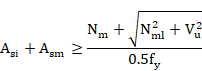
Where Ash and Asm are the areas of bonded reinforcement in the hoop and meridional direction, respectively.
Nhl and Nml are membrane forces, in the hoop and meridional direction, respectively, due to lateral loading such as earthquake, wind or tornado loads.
If lateral loads are not specified, Nhl and Nml will be zero. If the simplified method is specified in ~CHKPRS command (VAL5 = -1), they will be obtained by subtracting the loads due to prestressing, pressure and dead loads from the total loads.
The provided reinforcement Assip is compared to the required reinforcement, calculated using CC-3521.1.1, equations (12) and (13) with the following factors:
Tangential shear strength is provided by orthogonal reinforcement Vso:
![]()
(ACI 359-04 CC-3522(e))
This value shall not be greater than 0.5·0.2 f’cbt.
Where:
- Asi area of bonded reinforcement in one direction of inclined bars
- Vu is the maximum applied tangential shear Txy.
- t overall thickness of member.
Since inclined reinforcement is not considered by CivilFEM, the following equation shall be satisfied:
![]()
This limit is considered with the CivilFEM orthogonal reinforcement shear strength criterion as follows:
![]()
Additionally, if the tangential shear strength limit specified by RG 1.136 (SRP 3.8.1, Section II.5.A) is considered (set by the user in ~CHKPRS command) the following criterion will be:

The orthogonal reinforcement strength criterion is the larger of the two values. If the above criteria are greater than one, inclined reinforcement will be necessary.
NOTE: If the
orthogonal reinforcement shear strength limit is not satisfied, the reinforcing
amounts![]() and
and ![]() (equations 12 or 13 from CC-3521.1.1) are calculated and compared
to the reinforcement assigned to the shell vertex. However, the orthogonal
reinforcement limit criterion CRT_ASO will be greater than 1.
(equations 12 or 13 from CC-3521.1.1) are calculated and compared
to the reinforcement assigned to the shell vertex. However, the orthogonal
reinforcement limit criterion CRT_ASO will be greater than 1.
13.19.7.3 Service Loads - Primary Plus Secondary Loads, Except the Structural Integrity Test (SIT)
13.19.7.3.1 Concrete contribution
The allowable concrete stress for tangential shear shall be 67% (CC-3431.3) of the value given for the factored load.
13.19.7.3.2 Reinforcement contribution
If the nominal (applied) shear load is less than 50% of the allowable concrete shear load and the effective prestress is compressive, shear reinforcement will not be required. Therefore:
|
If: |
|
|
Then: |
|
Nh and Nm are membrane forces solely due to dead, pressure, and effective pre-stress loads that are labeled for the hoop and meridional direction, respectively (positive for tension, negative for compression).
|
If: |
|
|
Then: |
(ACI 359-04 CC-3521.1.1 Eqn.(12) and Eqn.(13) and CC-3522(c)) |


Where Ash and Asm are the areas of bonded reinforcement in the hoop and meridional direction, respectively.
Nhl and Nml are membrane forces, in the hoop and meridional direction, respectively, due to lateral loading such as earthquake, wind or tornado loads.
If the lateral loads are not specified, Nhl and Nml will be zero. If the simplified method is specified in ~CHKPRS command (VAL5 = -1), they will be obtained by subtracting the loads due to prestressing, pressure and dead loads from the total loads.
The provided reinforcement Assip is compared to the required reinforcement, calculated using CC-3521.1.1, equations (12) and (13) with the following factors:
Tangential shear strength provided by the orthogonal reinforcement Vso:
![]()
(ACI 359-04 CC-3522(e))
This value shall not be greater than 0.5·0.2 f’cbt.
Where:
- Asi area of bonded reinforcement in one direction of inclined bars
- Vu is the maximum applied tangential shear Txy.
- t overall thickness of member.
Since inclined reinforcement is not considered by CivilFEM, the following equation shall be satisfied:
![]()
This limit is considered with the CivilFEM orthogonal reinforcement shear strength criterion as follows:
![]()
Additionally, if the tangential shear strength limit specified by RG 1.136 (SRP 3.8.1, Section II.5.A) is considered (set by the user in ~CHKPRS command), the following criterion will be:
The orthogonal reinforcement strength criterion is the larger of the two values. If the above criteria are greater than one, inclined reinforcement will be necessary.
NOTE: If the
orthogonal reinforcement shear strength limit is not satisfied, the reinforcing
amounts ![]() and
and ![]() (equations 12 or 13 from CC-3521.1.1) are calculated and compared
to the reinforcement assigned to the shell vertex. However, the orthogonal
reinforcement limit criterion CRT_ASO will be greater than 1.
(equations 12 or 13 from CC-3521.1.1) are calculated and compared
to the reinforcement assigned to the shell vertex. However, the orthogonal
reinforcement limit criterion CRT_ASO will be greater than 1.
13.19.7.4 Service Loads - Primary Plus Secondary Loads Including the Structural Integrity Test (SIT)
13.19.7.4.1 Concrete contribution
The allowable concrete stress for tangential shear shall be 67% (CC-3431.3) of the value given for factored load.
13.19.7.4.2 Reinforcement contribution
If the nominal (applied) shear load is less than 50% of the allowable concrete shear load and the effective prestress is compressive, shear reinforcement will not be required. Therefore:
|
If: |
|
|
Then: |
|
Nh and Nm are membrane force solely due to dead, pressure, and effective pre-stress loads that are labeled for the hoop direction and meridional direction, respectively (positive for tension, negative for compression).
|
If: |
|
|
Then: |
(ACI 359-04 CC-3521.1.1 Eqn.(12) and Eqn.(13) and CC-3522(c)) |


Where Ash and Asm are the areas of bonded reinforcement in the hoop and meridional direction, respectively.
Nhl and Nml are membrane forces, in the hoop and meridional direction, respectively, due to lateral loading such as earthquake, wind or tornado loads.
If the lateral loads are not specified, Nhl and Nml will be zero. If the simplified method is specified in the ~CHKPRS command (VAL5 = -1), they will be obtained by subtracting the loads due to prestressing, pressure and dead loads from the total loads.
The provided reinforcement Assip is compared to the required reinforcement, calculated using CC-3521.1.1, equations (12) and (13) with the following factors:
Tangential shear strength provided by the orthogonal reinforcement Vso:
![]()
(ACI 359-04 CC-3522(e))
This value shall not exceed 0.5·0.2 f’cbt.
Where:
- Asi area of bonded reinforcement in one direction of inclined bars
- Vu maximum applied tangential shear Txy.
- t overall thickness of member.
Since inclined reinforcement is not considered by CivilFEM, the following equation shall be satisfied:
![]()
This limit is considered with the CivilFEM orthogonal reinforcement shear strength criterion as follows:
![]()
Additionally, if the tangential shear strength limit specified by RG 1.136 (SRP 3.8.1, Section II.5.A) is considered (set by the user in ~CHKPRS command), the following criterion will be:
The orthogonal reinforcement strength criterion is the larger of the two values. If the above criteria are greater than one, inclined reinforcement will be necessary.
NOTE: If the
orthogonal reinforcement shear strength limit is not satisfied, the reinforcing
amounts ![]() and
and ![]() (equations 12 or 13 from CC-3521.1.1) are calculated and compared
to the reinforcement assigned to the shell vertex. However the orthogonal
reinforcement limit criterion CRT_ASO will be greater than 1.
(equations 12 or 13 from CC-3521.1.1) are calculated and compared
to the reinforcement assigned to the shell vertex. However the orthogonal
reinforcement limit criterion CRT_ASO will be greater than 1.
13.19.7.5 Results
Checking results are stored in the CivilFEM results file:
|
VC |
Shear strength provided by concrete. |
|
CRT_ASX |
Reinforcement factor for X direction. |
|
CRT_ASY |
Reinforcement factor for Y direction. |
|
CRT_ASO |
Orthogonal reinforcement limit criterion. |
|
CRT_TOT |
Total criterion |
The reinforcement factor is the ratio between the required reinforcement and the reinforcement assigned to the shell vertex.
The total criterion is the maximum value of the reinforcement factor for each direction of the shell.
When no tangential shear reinforcement is needed, the reinforcement factors and criteria output will be zero.
13.19.8 Tangential shear design
Tangential shear is a membrane shear in the plane of shell element.
13.19.8.1 Factored loads
13.19.8.1.1 Concrete contribution
A minimum amount of effective prestress is provided in order to fulfill the following conditions (CC-3521.1.2):
![]()
![]()
The tangential shear strength provided by the concrete Vc shall be computed as follows:
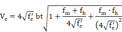
(ACI 359-04 CC-3421.5.2(Eqn.10))
Where:
- fm and fh Membrane stresses in the meridional direction (meridional) and the circumferential (hoop) direction, respectively. If these forces are compressive, they will be positive in the equation above.
- Nm and Nh Membrane forces (meridional and hoop) due to prestress, pressure and dead loads.
- Th and Tm Membrane forces (meridional and hoop) due to thermal loads.
Vc is taken as zero if the minimum amount of effective prestress is not present.
If it is identified that there is no effective prestress present, label VAL7 in the ~DIMPRS command can be set to -1.
13.19.8.1.2 Reinforcement contribution
If the nominal (applied) shear load is less than 85% of the allowable concrete shear load and if the effective prestress is compressive then shear reinforcing is not required. Therefore:
|
If: |
|
|
Then: |
|
|
Nh and Nm are membrane forces solely due to dead, pressure, and effective pre-stress loads that are labeled for the hoop and meridional direction, respectively, (positive for tension, negative for compression). |
||
|
|
||
|
If: |
|
|
|
Then: |
(ACI 359-04 CC-3521.1.1 (Eqn.12) and (Eqn.13)) |
|
Where Ash and Asm are the areas of bonded reinforcement in the hoop and meridional direction, respectively.
Nhl and Nml are membrane forces, in the hoop and meridional direction, respectively, due to lateral loading such as earthquake, wind or tornado loads.
If lateral loads are not specified, Nhl and Nml will be zero. If the simplified method is specified in ~DIMPRS command (VAL5 = -1), they will be obtained by subtracting the loads due to prestressing, pressure and dead loads from the total loads.
Tangential shear strength provided by the orthogonal reinforcement Vso:
![]()
(ACI 359-04 CC-3521.1.1(Eqn.14))
This value shall not exceed![]() .
.
Where:
- Asi area of bonded reinforcement in one direction of inclined bars
- Vu is the maximum applied tangential shear Txy.
- t overall thickness of member.
Since inclined reinforcement is not considered by CivilFEM, the following equation shall be satisfied:
![]()
This limit is considered with the CivilFEM orthogonal reinforcement shear strength criterion as follows:
![]()
Additionally, if the tangential shear strength limit specified by RG 1.136 (SRP 3.8.1, Section II.5.A) is considered (set by the user in ~DIMPRS command), the following criterion will be:
The orthogonal reinforcement strength criterion is the larger of the two values. If the above criteria are greater than one, inclined reinforcement will be necessary.
NOTE: If the
orthogonal reinforcement shear strength limit is not satisfied, the
reinforcement amounts ![]() and
and ![]() (equations 12 or 13 from CC-3521.1.1) are calculated and compared
to the reinforcement assigned to the shell vertex. However, the orthogonal
reinforcement limit criterion CRT_ASO will greater than 1.
(equations 12 or 13 from CC-3521.1.1) are calculated and compared
to the reinforcement assigned to the shell vertex. However, the orthogonal
reinforcement limit criterion CRT_ASO will greater than 1.
13.19.8.2 Service Loads - Primary Forces Only
13.19.8.2.1 Concrete contribution
The allowable concrete stress for tangential shear shall be 50% (CC-3431.3) of the value given for the factored load.
13.19.8.2.2 Reinforcement contribution
If the nominal (applied) shear load is less than 50% of the allowable concrete shear load and the effective prestress is compressive, shear reinforcement will not be required. Therefore:
|
If: |
|
|
Then: |
|
Nh and Nm are membrane forces solely due to dead, pressure, and effective pre-stress loads that are labeled for the hoop and meridional direction, respectively (positive for tension, negative for compression).
|
If: |
|
|
Then: |
(ACI 359-04 CC-3521.1.1 Eqn.(12) and Eqn.(13) and CC-3522(c)) |
Where Ash and Asm are the areas of bonded reinforcement in the hoop and meridional direction, respectively.
Nhl and Nml are membrane forces, in the hoop and meridional direction, respectively, due to lateral loading such as earthquake, wind or tornado loads.
If lateral loads are not specified, Nhl and Nml will be zero. If the simplified method is specified in ~DIMPRS command (VAL5 = -1), they will be obtained by subtracting the loads due to prestressing, pressure and dead loads from the total loads.
Tangential shear strength provided by the orthogonal reinforcement Vso:
![]()
(ACI 359-04 CC-3522(e))
This value shall not exceed ![]() .
.
Where:
- Asi area of bonded reinforcement in one direction of inclined bars
- Vu maximum applied tangential shear Txy.
- t overall thickness of member.
Since inclined reinforcement is not considered by CivilFEM, the following equation shall be satisfied:
![]()
This limit is considered with the CivilFEM orthogonal reinforcement shear strength criterion as follows:
Additionally, if the tangential shear strength limit specified by RG 1.136 (SRP 3.8.1, Section II.5.A) is considered (set by the user in ~DIMPRS command), the following criterion will be:
The orthogonal reinforcement strength criterion is the larger of the two values. If the above criteria are greater than one, inclined reinforcement will be necessary.
NOTE: If the
orthogonal reinforcement shear strength limit is not satisfied, the reinforcementamounts
![]() and
and ![]() (equations 12 or 13 from CC-3521.1.1) are calculated and compared
to the reinforcement assigned to the shell vertex. However, the orthogonal
reinforcement limit criterion CRT_ASO will be greater than 1.
(equations 12 or 13 from CC-3521.1.1) are calculated and compared
to the reinforcement assigned to the shell vertex. However, the orthogonal
reinforcement limit criterion CRT_ASO will be greater than 1.
13.19.8.3 Service Loads - Primary Plus Secondary Loads, Except the Structural Integrity Test (SIT)
13.19.8.3.1 Concrete contribution
The allowable concrete stress for tangential shear shall be 67% (CC-3431.3) of the value given for the factored load.
13.19.8.3.2 Reinforcement contribution
If the nominal (applied) shear load is less than 50% of the allowable concrete shear load and the effective prestress is compressive, shear reinforcement will not be required. Therefore:
|
If: |
|
|
Then: |
|
Nh and Nm are membrane forces solely due to dead, pressure, and effective pre-stress loads that are labeled for the hoop and meridional direction, respectively, (positive for tension, negative for compression).
|
If |
|
|
|
Then |
(ACI 359-04 CC-3521.1.1 Eqn.(12) and Eqn.(13) and CC-3522(c)) |
|
Where Ash and Asm are the areas of bonded reinforcement in the hoop and meridional direction, respectively.
Nhl and Nml are membrane forces, in the hoop and meridional direction, respectively, due to lateral loading such as earthquake, wind or tornado loads.
If the lateral loads are not specified, Nhl and Nml will be zero. If the simplified method is specified in ~DIMPRS command (VAL5 = -1), they will be obtained by subtracting the loads due to prestressing, pressure and dead loads from the total loads.
Tangential shear strength provided by the orthogonal reinforcement Vso:
![]()
(ACI 359-04 CC-3522(e))
This value shall not exceed ![]() .
.
Where:
- Asi area of bonded reinforcement in one direction of inclined bars
- Vu maximum applied tangential shear Txy.
- t overall thickness of member.
Since inclined reinforcement is not considered by CivilFEM, the following equation shall be satisfied:
![]()
This limit is considered with the CivilFEM orthogonal reinforcement shear strength criterion as follows:
![]()
Additionally, if the tangential shear strength limit specified by RG 1.136 (SRP 3.8.1, Section II.5.A) is considered (set by the user in ~DIMPRS command), the following criterion will be:
The orthogonal reinforcement strength criterion is the larger of the two values. If the above criteria are greater than one, inclined reinforcement will be required.
NOTE: If the
orthogonal reinforcement shear strength limit is not satisfied, the reinforcing
amounts ![]() and
and ![]() (equations 12 or 13 from CC-3521.1.1) are calculated and compared
to the reinforcement assigned to the shell vertex. However, the orthogonal
reinforcement limit criterion CRT_ASO will be greater than 1.
(equations 12 or 13 from CC-3521.1.1) are calculated and compared
to the reinforcement assigned to the shell vertex. However, the orthogonal
reinforcement limit criterion CRT_ASO will be greater than 1.
13.19.8.4 Service Loads - Primary Plus Secondary Loads Including the Structural Integrity Test (SIT)
13.19.8.4.1 Concrete contribution
The allowable concrete stress for tangential shear shall be 67% (CC-3431.3) of the value given for the factored load.
13.19.8.4.2 Reinforcement contribution
If the nominal (applied) shear load is less than 50% of the allowable concrete shear load and the effective prestress is compressive, shear reinforcement will not be required. Therefore:
|
If: |
|
|
Then: |
|
Nh and Nm are membrane forces solely due to dead, pressure, and effective pre-stress loads that are labeled in the hoop and meridional direction, respectively (positive for tension, negative for compression).
|
If: |
|
|
Then: |
(ACI 359-04 CC-3521.1.1 Eqn.(12) and Eqn.(13) and CC-3522(c)) |
Where Ash and Asm are the areas of bonded reinforcement in the hoop and meridional direction, respectively.
Nhl and Nml are membrane forces, in the hoop and meridional direction, respectively, due to lateral loading such as earthquake, wind or tornado loads.
If the lateral loads are not specified, Nhl and Nml will be zero. If the simplified method is specified in ~DIMPRS command (VAL5 = -1), they will be obtained by subtracting the loads due to prestressing, pressure and dead loads from the total loads.
Tangential shear strength provided by the orthogonal reinforcement Vso:
![]()
(ACI 359-04 CC-3522)
This value shall not exceed![]() .
.
Where:
- Asi area of bonded reinforcement in one direction of inclined bars
- Vu maximum applied tangential shear Txy.
- t overall thickness of member.
Since inclined reinforcement is not considered by CivilFEM, the following equation shall be satisfied:
![]()
This limit is considered with the CivilFEM orthogonal reinforcement shear strength criterion as follows:
![]()
Additionally, if the tangential shear strength limit specified by RG 1.136 (SRP 3.8.1, Section II.5.A) is considered (set by the user in ~DIMPRS command), the following criterion is considered:
The orthogonal reinforcement strength criterion is the larger of the two values. If the above criteria are greater than one, inclined reinforcement will be necessary.
NOTE: If the orthogonal reinforcement shear
strength limit is not satisfied, the reinforcement amounts ![]() and
and ![]() (equations 12 or 13 from CC-3521.1.1) are calculated and compared
to the reinforcement assigned to the shell vertex. However the orthogonal
reinforcement limit criterion CRT_ASO will be greater than 1.
(equations 12 or 13 from CC-3521.1.1) are calculated and compared
to the reinforcement assigned to the shell vertex. However the orthogonal
reinforcement limit criterion CRT_ASO will be greater than 1.
13.19.8.5 Results
Design results are stored in the CivilFEM results file:
|
VC |
Shear strength provided by concrete. |
|
ASX |
Reinforcement amount (area per unit length) for X direction. |
|
ASY |
Reinforcement amount (area per unit length) for Y direction. |
|
CRT_ASO |
Orthogonal reinforcement limit criterion. |
|
DSG_CRT |
Total design criterion |
DSG_CRT is the criterion that would be obtained in checking if the reinforcement is the one provided by the design process.
13.19.9 Flexure and axial check
Flexure and axial checking is performed using an interaction diagram to obtain the stress distribution for steel and concrete. This diagram is obtained from the materials' strength for each end of the vertex in the X and Y directions.
Refer to Sections 13.1.3 and 13.1.4 for additional information on interaction diagrams.
13.19.9.1 Allowable Stresses for Factored Loads
13.19.9.1.1 Concrete
13.19.9.1.1.1 Compression
The compression normal stresses shall not exceed the following limits: (Table CC-3421-1)
|
|
ALLOWABLE STRESSES |
|
|
|
MEMBRANE |
MEMBRANE+FLEXURE(2) |
|
PRIMARY |
|
|
|
PRIMARY+SECONDARY(1) |
|
|
(1) The primary portion of this calculated stress shall not exceed the allowable stress applicable when primary stress acts alone.
(2) The membrane checking and flexure are independent; therefore, both must be computed.
(3) The maximum allowable primary-plus-secondary membrane and bending compressive stress of 0.85f’c shall not exceed a limiting strain of 0.002. The most restrictive limit will be used.
The membrane limit is used to calculate the pure compression point on the interaction diagram by setting the C Pivot of the diagram (refer to Chapter 11-A.3.1).
13.19.9.1.1.2 Tension
Concrete tensile strength is not considered (CC-3421.2).
13.19.9.1.2 Reinforcing Steel
The design yield strength, fy, shall not exceed 60,000 psi (CC-3422.1). However, this limit can be modified in the checking command (~CHKPRS).
The allowable stress for load resistance shall not exceed the following (CC-3422.1 and CC-3422.2):
|
|
ALLOWABLE STRESSES |
|
|
|
TENSION |
COMPRESSION |
|
PRIMARY |
|
|
|
PRIMARY+SECONDARY |
|
|
In general, stresses in the steel shall not exceed the allowable stress specified above. However, strains may exceed the yield strength when the reinforcement is used with concrete that requires larger strains for developing full capacity.
This is equivalent to a steel stress-strain diagram with the limit for the inclined branch of the allowable stress specified above.
13.19.9.2 Allowable Stresses for Service Loads
13.19.9.2.1 Concrete
13.19.9.2.1.1 Compression
The compression normal stresses shall not exceed the following limits: (Table CC-3431-1)
|
|
ALLOWABLE STRESSES |
|
|
|
MEMBRANE |
MEMBRANE+FLEXURE(2) |
|
PRIMARY |
|
|
|
PRIMARY+SECONDARY(1) |
|
|
|
PRIMARY+SIT (3) |
|
|
|
PRIMARY+SECONDARY+SIT(3) |
|
|
|
PRIMARY+SIT (RG1.90) (4) |
|
|
|
PRIMARY+SECONDARY+SIT (RG1.90) (4) |
|
|
(1) The primary portion of this calculated stress shall not exceed the allowable stress applicable when primary stress acts alone.
(2) The membrane checking and flexure are independent; therefore, both must be computed.
(3) Structural Integrity Test.
(4) Regulatory Guide 1.90.
The membrane limit is used to calculate the pure compression point on the interaction diagram by setting the C Pivot of the diagram (refer to Chapter 11-A.3.1).
13.19.9.2.1.2 Tension
Concrete tensile strength is not considered (CC-3421.2).
13.19.9.2.2 Reinforcing Steel
The design yield strength, fy, shall not exceed 60,000 psi (CC-3422.1). However, this limit can be modified in the checking command (~CHKPRS).
The allowable stress for load resistance shall not exceed the following. (CC-3432.1 and CC-3422.2).
|
|
ALLOWABLE STRESSES |
|
|
|
TENSION |
COMPRESSION |
|
PRIMARY |
|
|
|
PRIMARY+SECONDARY |
|
|
|
PRIMARY+SIT (1) |
|
|
|
PRIMARY+SECONDARY+SIT(1) |
|
|
|
PRIMARY+SIT (RG1.90) (2) |
|
|
|
PRIMARY+SECONDARY+SIT (RG1.90) (2) |
|
|
(1) Structural Integrity Test: Stress limits may be increased by 50% when the temporary pressure loads during the test condition are combined with primary or primary plus secondary loads
(2) Regulatory Guide 1.90: Section III, Division 2, of the ASME Code allows an increase of the allowable stress in tensile reinforcement under a test condition. However, if such testing is to be performed a number of times during the life of the structure, it is advised not to use this allowance to avoid the gradual propagation of cracks.
In general, stresses in the steel shall not exceed the allowable stress specified above. However, strains may exceed the yield strength when the reinforcement is used with concrete that requires larger strains for developing full capacity.
This is equivalent to a steel stress-strain diagram with the limit for the inclined branch of the allowable stress specified above.
13.19.9.2.3 Results
Figure 13.14‑1 Determination of the homothetic strain state
This criterion is defined as the ratio between two distances, d1 and d2. The distance d1 is from the “center” of the diagram (point A of Figure 13.12‑1) to the point which represents the acting forces and moments (point P of Figure 13.12‑1). Distance d2 is defined between the center and the point which represents the homothetic ultimate forces and moments (point B).
If the criterion is less than 1.00, this indicates the forces and moments acting on the section are below the ultimate strength and the section is safe. On the contrary, for criterion higher than 1.00, the section will be considered under-reinforced.
Note: Refer to Chapter 11-A.3: Interaction diagram for additional information.
Checking results are stored in the CivilFEM results file:
|
CRT_X |
Criterion for X direction |
|
CRT_Y |
Criterion for Y direction. |
|
CRT_TOT |
Total criterion. |
CRT_TOT is the maximum value of CRT_X and CRT_Y.
13.19.10 Flexure and axial design
Flexure and axial design is performed using an interaction diagram to obtain the stress distribution for steel and concrete. This diagram is obtained from the materials' strength for the vertex in the X and Y direction.
Refer to Sections 13.1.3 and 13.1.4 for additional information on interaction diagrams.
For each direction, CivilFEM will obtain the reinforcement that produces a criterion of 1.00 (see flexure and axial checking) with a tolerance of 1%.
13.19.10.1 Allowable Stresses for Factored Loads
13.19.10.1.1 Concrete
13.19.10.1.1.1 Compression
The compression normal stresses shall not exceed the following limits: (Table CC-3421-1)
|
|
ALLOWABLE STRESSES |
|
|
|
MEMBRANE |
MEMBRANE+FLEXURE(2) |
|
PRIMARY |
|
|
|
PRIMARY+SECONDARY(1) |
|
|
(1) The primary portion of this calculated stress shall not exceed the allowable stress applicable when primary stress acts alone.
(2) The membrane checking and flexure are independent, both must be computed.
(3) The maximum allowable primary-plus-secondary membrane and bending compressive stress of 0.85f’c shall not exceed a limiting strain of 0.002. The most restrictive limit will be used
The membrane limit is used to calculate the pure compression point on the interaction diagram by setting the C Pivot of the diagram (refer to Chapter 11-A.3.1).
13.19.10.1.1.2 Tension
Concrete tensile strength is not considered. (CC-3421.2)
13.19.10.1.2 Reinforcing steel
The design yield strength, fy, shall not exceed 60,000 psi (CC-3422.1). However, this limit can be modified in the design command (~DIMPRS).
The allowable stress for load resistance shall not exceed the following (CC-3422.1, CC-3422.2):
|
|
ALLOWABLE STRESSES |
|
|
|
TENSION |
COMPRESSION |
|
PRIMARY |
|
|
|
PRIMARY+SECONDARY(1) |
|
|
In general, stresses in the steel shall not exceed the allowable stress specified above. However, strains may exceed the yield strength when the reinforcement is used with concrete that requires larger strains for developing full capacity.
This is equivalent to a steel stress-strain diagram with the limit for the inclined branch of the allowable stress specified above.
13.19.10.2 Allowable Stresses for Serviced Loads
13.19.10.2.1 Concrete
13.19.10.2.1.1 Compression
The compression normal stresses shall not exceed the following limits: (Table CC-3431-1)
|
|
ALLOWABLE STRESSES |
|
|
|
MEMBRANE |
MEMBRANE+FLEXURE(2) |
|
PRIMARY |
|
|
|
PRIMARY+SECONDARY(1) |
|
|
|
PRIMARY+SIT (3) |
|
|
|
PRIMARY+SECONDARY+SIT(3) |
|
|
|
PRIMARY+SIT (RG1.90) (4) |
|
|
|
PRIMARY+SECONDARY+SIT (RG1.90) (4) |
|
|
(1) The primary portion of this calculated stress shall not exceed the allowable stress applicable when primary stress acts alone.
(2) The membrane checking and flexure are independent; therefore, both must be computed.
(3) Structural Integrity Test.
(4) Regulatory Guide 1.90.
The membrane limit is used to calculate the pure compression point on the interaction diagram by setting the C Pivot of the diagram (refer to Chapter 11-A.3.1).
13.19.10.2.1.2 Tension
Concrete tensile strength is not considered (CC-3421.2)
13.19.10.2.2 Reinforcing Steel
The design yield strength, fy, shall not exceed 60,000 psi (CC-3422.1). However, this limit can be modified in the design command (~DIMPRS).
The allowable stress for load resistance shall not exceed the following. (CC-3432.1, CC-3432.2)
|
|
ALLOWABLE STRESSES |
|
|
|
TENSION |
COMPRESSION |
|
PRIMARY |
|
|
|
PRIMARY+SECONDARY |
|
|
|
PRIMARY+SIT (1) |
|
|
|
PRIMARY+SECONDARY+SIT(1) |
|
|
|
PRIMARY+SIT (RG1.90) (2) |
|
|
|
PRIMARY+SECONDARY+SIT (RG1.90) (2) |
|
|
(1) Structural Integrity Test: the stress limits may be increased by 50% when the temporary pressure loads during the test condition are combined with primary or primary plus secondary loads
(2) Regulatory Guide 1.90: Section III, Division 2, of the ASME Code allows an increase of the allowable stress in tensile reinforcement under a test condition. However, if such testing is to be performed a number of times during the life of the structure, it is prudent not to use this allowance to avoid gradual propagation of cracking.
In general, stresses in the steel shall not exceed the allowable stress specified above. However, strains may exceed the yield strength when the reinforcement is used with concrete that requires larger strains for developing full capacity.
This is equivalent to a steel stress-strain diagram with the limit for the inclined branch of the allowable stress specified above.
13.19.10.2.3 Results
Design results are stored in the CivilFEM results file:
|
ASTX |
Reinforcement amount at X top. |
|
ASBX |
Reinforcement amount at X bottom. |
|
ASTY |
Reinforcement amount at Y top. |
|
ASBY |
Reinforcement amount at Y bottom. |
|
DSG_CRT |
Total criterion. |
13.19.11 Flexure, axial and shear design
This global design is composed of all of the design types described in the previous chapters: membrane and bending, tangential shear and radial shear design.
13.19.11.1 Procedure
The comments and explanations for radial shear design, tangential shear design, and flexure and axial design in chapters 13.14.6, 13.14.8, and 13.14.10 will also apply for this global design option.
For more information see ~DIMPRS command (Lab2 = BEND_SHR).
Reinforcement material and mechanical cover must be defined in the corresponding shell vertex (bending reinforcement), see ~SHLRNF command.
Additionally, reinforcement material must be defined in the corresponding shell vertex for the following reinforcements:
- Shear reinforcement: see ~SHLSHR command.
- In-plane shear reinforcement: see ~SHLIPSH command.
13.19.11.2 Results
Design results summarize all previous design types and are stored in the CivilFEM results file:
|
ASTX |
Reinforcement amount at X top. |
|
ASBX |
Reinforcement amount at X bottom. |
|
ASTY |
Reinforcement amount at Y top. |
|
ASBY VC |
Reinforcement amount at Y bottom. Tangential shear strength provided by concrete. |
|
ASX |
Reinforcement amount for in plane shear, X direction. |
|
ASY |
Reinforcement amount for in plane shear, Y direction. |
|
CRT_ASO |
Orthogonal reinforcement limit criterion. |
|
VC_X |
Allowable radial shear stress in concrete, X direction. |
|
VS_X |
Shear strength provided by radial shear reinforcement, X direction. |
|
VU_X |
Nominal radial shear stress, X direction |
|
ASSH_X |
Area per unit length of radial shear reinforcement, X direction. |
|
VC_Y |
Allowable radial shear stress in concrete, Y direction. |
|
VS_Y |
Shear strength provided by radial shear reinforcement, Y direction. |
|
VU_Y |
Nominal radial shear stress, Y direction |
|
ASSH_Y |
Area per unit length of radial shear reinforcement, Y direction. |
|
ASSH |
Area per unit area of radial shear reinforcement. |
|
DSG_2D |
Bending plus axial design criterion. |
|
DSG_TSH |
Tangential shear design criterion. |
|
DSG_RSH |
Radial shear design criterion. |
|
DSG_CRT |
Total design criterion. |
13.20 Cracking Checking according Eurocode 2 (EN 1992-1-1:2004/AC:2008)
13.20.1 Cracking Checking
The cracking check calculates the crack width and checks the following condition:
![]()
where:
![]() Design crack width.
Design crack width.
![]() Maximum crack width (argument of ~CHKCON
command)
Maximum crack width (argument of ~CHKCON
command)
The design crack width is obtained from the following expression (Art. 7.3.4):
![]()
![]() Maximum spacing between cracks.
Maximum spacing between cracks.
![]() Mean strain in the reinforcement.
Mean strain in the reinforcement.
![]() Mean strain in the concrete between bars.
Mean strain in the concrete between bars.


f Reinforcement bar size in mm (obtained with the shell reinforcement definition by spacing and diameters, see ~SHLRNF command).
![]() Effective reinforcement ratio, where Ac,eff is the
effective area of concrete in tension, As is the area of
reinforcement contained within the effective concrete area and Ap’
is the area of pre- or post-tensioned tendons within Ac,eff. CivilFEM
calculates this value with
Effective reinforcement ratio, where Ac,eff is the
effective area of concrete in tension, As is the area of
reinforcement contained within the effective concrete area and Ap’
is the area of pre- or post-tensioned tendons within Ac,eff. CivilFEM
calculates this value with ![]() and
and
![]()
![]() Coefficient accounting for the influence of the bond
properties of the bonded reinforcement (argument of ~CHKCON
command).
Coefficient accounting for the influence of the bond
properties of the bonded reinforcement (argument of ~CHKCON
command).
![]() Coefficient accounting for the influence of the form of the
strain distribution:
Coefficient accounting for the influence of the form of the
strain distribution:
![]()
Where ![]() is the
larger tensile strain and
is the
larger tensile strain and![]() is the
smaller tensile strain at the boundary of a section subjected to eccentric
tension.
is the
smaller tensile strain at the boundary of a section subjected to eccentric
tension.
![]() Constants defined in the National Annexes (arguments of the ~CHKCON command).
Constants defined in the National Annexes (arguments of the ~CHKCON command).
c Cover to the longitudinal reinforcement. (obtained with the shell reinforcement definition, see ~ SHLRNF command).
![]() Stress in the tensile reinforcement calculated for a cracked
section.
Stress in the tensile reinforcement calculated for a cracked
section.
![]() Elastic modulus of the longitudinal reinforcement.
Elastic modulus of the longitudinal reinforcement.
![]() Coefficient accounting for the influence of the duration of
the loading (argument of ~CHKCON command).
Coefficient accounting for the influence of the duration of
the loading (argument of ~CHKCON command).
![]() Ratio between steel-concrete elastic modulus (Es/Ecm).
Ratio between steel-concrete elastic modulus (Es/Ecm).
13.20.2 Reinforcement Stress Calculation
During the calculation process, it is necessary to determine the reinforcement stress under service loads (ss) with the assumption the section is cracked.
The calculation of these stresses is an iterative process in which CivilFEM searches for the deformation plane that causes a stress state that is in equilibrium with the external loads. The reinforcement stress is obtained from this deformation plane and from the reinforcement position.
The design loads are taken as external loads for the case of serviceability stress calculation. For the stress calculation at the instant the crack appears, the external loads are taken as homothetic to the design loads that cause a stress equivalent to the concrete tensile strength in the fiber under the greatest amount of tension.
If the loads acting on the cross section cause collapse under axial plus bending checking, the cross section and the associated element are labeled as non-checked.
13.20.3 Checking Results
Checking results are stored in the corresponding alternative in the CivilFEM results file (*.RCV).
The following results are available (see ~PLLSCON and ~PRCON commands):
|
CRT_TOT_X |
Cracking criterion. |
||||||
|
SIGMA_X |
Maximum tensile stress. |
||||||
|
WK_X |
Design crack width |
||||||
|
SRMAX_X |
Maximum spacing between cracks. |
||||||
|
EM_X |
Difference between the mean strain in the
reinforcement and the mean strain in concrete |
||||||
|
POS_X |
Cracking position inside the section
|
||||||
|
|
|
||||||
|
CRT_TOT_Y |
Cracking criterion. |
||||||
|
SIGMA_Y |
Maximum tensile stress. |
||||||
|
WK_Y |
Design crack width |
||||||
|
SRMAX_Y |
Maximum spacing between cracks. |
||||||
|
EM_Y |
Difference between the mean strain in the
reinforcement and the mean strain in concrete |
||||||
|
POS_Y |
Cracking position inside the section.
|
||||||
|
|
|
||||||
|
SIG_X_T |
Maximum tensile stress on X direction (TOP) |
||||||
|
WK_X_T |
Design crack width on X direction (TOP) |
||||||
|
SRMX_X_T |
Maximum crack spacing on X direction (TOP) |
||||||
|
EM_X_T |
Difference between the mean strain in reinf.and concrete(X TOP) |
||||||
|
CRT_X_T |
Cracking criterion on X direction (TOP) |
||||||
|
SIG_X_B |
Maximum tensile stress on X direction (BOTTOM) |
||||||
|
WK_X_B |
Design crack width on X direction (BOTTOM) |
||||||
|
SRMX_X_B |
Maximum crack spacing on X direction (BOTTOM) |
||||||
|
EM_X_B |
Difference between the mean strain in reinf.and concrete(X BOT) |
||||||
|
CRT_X_B |
Cracking criterion on X direction (BOTTOM) |
||||||
|
SIG_Y_T |
Maximum tensile stress on Y direction (TOP) |
||||||
|
WK_Y_T |
Design crack width on Y direction (TOP) |
||||||
|
SRMX_Y_T |
Maximum crack spacing on Y direction (TOP) |
||||||
|
EM_Y_T |
Difference between the mean strain in reinf.and concrete(Y TOP) |
||||||
|
CRT_Y_T |
Cracking criterion on Y direction (TOP) |
||||||
|
SIG_Y_B |
Maximum tensile stress on Y direction (BOTTOM) |
||||||
|
WK_Y_B |
Design crack width on Y direction (BOTTOM) |
||||||
|
SRMX_Y_B |
Maximum crack spacing on Y direction (BOTTOM) |
||||||
|
EM_Y_B |
Difference between the mean strain in reinf.and concrete(Y BOT) |
||||||
|
CRT_Y_B |
Cracking criterion on Y direction (BOTTOM) |
||||||
|
COMP_X |
Maximum compressive stresses in the concrete on X direction |
||||||
|
COMP_Y |
Maximum compressive stresses in the concrete on Y direction |
||||||
|
RHOR_X_T |
Effective reinforcement ratio X direction (TOP) |
||||||
|
RHOR_X_B |
Effective reinforcement ratio X direction (BOTTOM) |
||||||
|
RHOR_Y_T |
Effective reinforcement ratio Y direction (TOP) |
||||||
|
RHOR_Y_B |
Effective reinforcement ratio Y direction (BOTTOM) |
||||||
|
K2_X |
K2 coefficient to take account distribution of strain (X dir.) |
||||||
|
K2_Y |
K2 coefficient to take account distribution of strain (Y dir.) |
||||||
|
NEUTR_X |
Neutral axis dist. from most compressed concrete fiber(X dir.) (=0 if both faces are in tension) |
||||||
|
NEUTR_Y |
Neutral axis dist. from most compressed concrete fiber(Y dir.) (=0 if both faces are in tension) |
For the cracking check (wmax > 0) the total criterion is defined as:
![]()
For decompression checking (wmax = 0) the total criterion is defined as:
![]()
where
![]() concrete design compressive strength
concrete design compressive strength
![]() Maximum section stress (positive tension). It corresponds to the
SIGMA result. (If CRT_TOT is negative, it’s taken as zero)
Maximum section stress (positive tension). It corresponds to the
SIGMA result. (If CRT_TOT is negative, it’s taken as zero)
Therefore, values for the total criterion larger than one indicate that the section does not pass as valid for this code.
13.21 Cracking Checking according to ACI 318-05, ACI 318-14 and ACI 318-19
13.21.1 Cracking Checking
Checking of the Cracking Limit State according to ACI 318-05 and ACI 318-14 consists of the following condition:
![]()
Where:
![]() Reinforcement spacing closest to the fiber in tension
(argument of ~CHKCON command)
Reinforcement spacing closest to the fiber in tension
(argument of ~CHKCON command)
S Design reinforcement spacing
CivilFEM checks this condition by applying the general calculation method for the reinforcement spacing (Art. 10.6.4):
![]()
![]()
where:
![]() Calculated stress in reinforcement at service loads.
Calculated stress in reinforcement at service loads.
![]() Geometrical cover (cross section code property, see ~SHLRNF command)
Geometrical cover (cross section code property, see ~SHLRNF command)
13.21.2 Reinforcement Stress Calculation
During the calculation process, it’s necessary to determine the reinforcement stress under service loads (fs).
The calculation of the stresses is an iterative process in which the program searches for the deformation plane that causes a stress state that is in equilibrium with the external loads. The reinforcement stress is obtained from this deformation plane and from the reinforcement position.
The design loads are taken as external loads.
If the loads acting on the cross section cause collapse under axial plus bending checking, the cross section and the element to which it belongs are marked as non checked.
13.21.3 Checking Results
Checking results are stored in the corresponding alternative in the CivilFEM results file (*.RCV).
The following results are available (see ~PLLSCON and ~PRCON commands):
|
CRT_TOT_X |
Cracking criterion in X direction. |
|||||||
|
S_X |
Design reinforcement spacing in X direction. |
|||||||
|
FS_X |
Reinforcement stress in X direction. |
|||||||
|
SIGMA_X |
Maximum tensile stress in X direction. |
|||||||
|
POS_X |
Cracking position inside the section in X direction.
|
|||||||
|
CRT_TOT_Y |
Cracking criterion in Y direction. |
|||||||
|
S_Y |
Design reinforcement spacing in Y direction. |
|||||||
|
FS_Y |
Reinforcement stress in Y direction. |
|||||||
|
SIGMA_Y |
Maximum tensile stress in Y direction. |
|||||||
|
POS_Y |
Cracking position inside the section in Y direction.
|
|||||||
For the cracking check (sd > 0) the total criterion is defined as:
![]()
For decompression checking (sd = 0) the total criterion is defined as:
![]()
where
![]() concrete design compressive strength.
concrete design compressive strength.
![]() Maximum section stress (positive tension), corresponding to the
SIGMA result. (If CRT_TOT is negative, it is taken as zero)
Maximum section stress (positive tension), corresponding to the
SIGMA result. (If CRT_TOT is negative, it is taken as zero)
Therefore, the values for the total criterion larger than one indicate that the section is not considered valid for this code.
13.22 Cracking Checking according to Code of Rules 52-101-03 and SP 63.13330.2012
13.22.1 Cracking Checking
Checking of the Cracking Limit State according to СП 52-101-03 and СП 63.13330.2012 follows the next steps.
First crack check is performed and critical moment is obtained and compared with design moment.


 .
.
Then crack opening check is performed and the crack widths are calculated for each element as follows:

Coefficients φ are introduced by the user in the ~CHKCON command.
φ1 is the coefficient considering
durability of loading, assumed equal to:
1.0 – at short-term loading.
1.4 – at long-term loading.
φ2 is the coefficient considering profile of longitudinal reinforcement,
assumed equal to:
0.5 – for ribbed-profile and reinforcing wires;
0.8 – for plain reinforcement.
φ3 is the coefficient considering type of loading, assumed equal to:
1.0 – for bending and eccentrically compressed members;
1.2 – for tensioned members.
![]() is the stress in the tensile reinforcement.
is the stress in the tensile reinforcement.
![]() is the basic distance between adjacent normal cracks and is assumed
not less than 10 times the nominal reinforcement diameter and 10 cm and not
more than 40 times the nominal reinforcement diameter and 40 cm
is the basic distance between adjacent normal cracks and is assumed
not less than 10 times the nominal reinforcement diameter and 10 cm and not
more than 40 times the nominal reinforcement diameter and 40 cm

Where:
![]() is the sectional area of tensile concrete, determined by the height
of the concrete tension zone. In any case
is the sectional area of tensile concrete, determined by the height
of the concrete tension zone. In any case ![]() is assumed not less than 2 times mechanical cover of tensile
reinforcement and not more than half of total thickness
is assumed not less than 2 times mechanical cover of tensile
reinforcement and not more than half of total thickness
![]() is the sectional area of tensile reinforcement.
is the sectional area of tensile reinforcement.
![]() is the nominal reinforcement diameter.
is the nominal reinforcement diameter.
![]() is the coefficient considering non-uniform tensile reinforcement
strains between cracks
is the coefficient considering non-uniform tensile reinforcement
strains between cracks
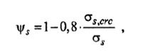
Where:
![]() is the stress in tensile reinforcement for critical moment
is the stress in tensile reinforcement for critical moment
13.22.2 Checking Results
Checking results are stored in the corresponding alternative in the CivilFEM results file (*.RCV).
The following results are available (see ~PLLSCON and ~PRCON commands):
|
MCRT_X |
Critical moment on X direction |
|
CRT_MX |
Moment/Critical moment on X direction. |
|
X_M_X |
Height of compression zone on X direction. |
|
ABT_X |
Sectional area of tensile concrete on X direction. |
|
LS_X |
Basic distance between cracks on X direction. |
|
ACRC_X |
Crack width on X direction. |
|
CRTTOT_X |
Cracking criterion on X direction |
|
MCRT_Y |
Critical moment on Y direction |
|
CRT_MY |
Moment/Critical moment on Y direction. |
|
X_M_Y |
Height of compression zone on Y direction. |
|
ABT_Y |
Sectional area of tensile concrete on Y direction. |
|
LS_Y |
Basic distance between cracks on Y direction. |
|
ACRC_Y |
Crack width on Y direction. |
|
CRTTOT_Y |
Cracking criterion on Y direction |