

11-B.1 Introduction
11-B.2 Shear and Torsion according to EHE-98
11-B.2.1 Shear Checking
The checking for shear according to EHE-98 follows the following steps:
1) Obtaining material strength properties. These properties are obtained from the material properties associated to each transverse cross section and for the active time.
The required data are the following ones:
![]() characteristic compressive strength of concrete.
characteristic compressive strength of concrete.
![]() characteristic yield strength of reinforcement.
characteristic yield strength of reinforcement.
![]() mean tensile strength of concrete.
mean tensile strength of concrete.
![]() concrete partial safety factor.
concrete partial safety factor.
![]() steel partial safety factor.
steel partial safety factor.
2) Obtaining geometrical data of the section. Geometrical requirements of the section must be defined within the CivilFEM database (~CSECDMS commands). Required data for shear checking are the following ones:
![]() total area of the concrete section.
total area of the concrete section.
3) Obtaining geometrical parameters depending on code. Geometrical parameters used for shear calculations must be defined within CivilFEM database (see ~SECMDF command). Required data are the following:
![]() Width of element in VY
direction equal to the total width in solid sections or in case of box
sections, the width equals the sum of the width of both webs. (parameter BW_VY
or BW_VZ of ~SECMDF command).
Width of element in VY
direction equal to the total width in solid sections or in case of box
sections, the width equals the sum of the width of both webs. (parameter BW_VY
or BW_VZ of ~SECMDF command).
d effective depth of the section, (parameter D_Y or D_Z of ~SECMDF command).
![]() geometric ratio of the tensile longitudinal
reinforcement anchored at a distance greater than or equal to d from the
considered section, (parameter RHO1 of ~SECMDF
command):
geometric ratio of the tensile longitudinal
reinforcement anchored at a distance greater than or equal to d from the
considered section, (parameter RHO1 of ~SECMDF
command):
![]()
q Angle of the concrete compressive struts with the member’s longitudinal axis, (parameter THETA of ~SECMDF command):
0.5
![]() cot
cot ![]()
Section 11-A.7 “Previous Considerations to Shear and Torsion Calculation” provides detailed information on how to calculate the required data for each code and valid section.
4) Obtaining section reinforcement data. Data concerning reinforcements of the section must be included within CivilFEM database, (see ~RNFDEF and ~RNFMDF commands). Required data are the following ones:
a angle between shear reinforcement and the longitudinal axis of the member, (parameter ALPHA of ~RNFDEF or ~RNFMDF command).
![]() area of reinforcement per unit of length, (parameter AS/S
of ~RNFDEF or ~RNFMDF
command).
area of reinforcement per unit of length, (parameter AS/S
of ~RNFDEF or ~RNFMDF
command).
The reinforcement ratio may also be obtained with the following data:
![]() total area of the reinforcement legs, (parameter AS of ~RNFDEF or ~RNFMDF
command).
total area of the reinforcement legs, (parameter AS of ~RNFDEF or ~RNFMDF
command).
s spacing of the stirrups, (parameter S of ~RNFDEF or ~RNFMDF command).
Or with the following ones:
s spacing of the stirrups, (parameter S of ~RNFDEF or ~RNFMDF command).
f diameter of bars, (parameter PHI of ~RNFDEF or ~RNFMDF command).
N number of reinforcement legs, (parameter N of ~RNFDEF or ~RNFMDF command).
5) Obtaining forces and moments acting on the section. The shear force that acts on the section as well as the concomitant axial force and bending moment are obtained from the CivilFEM results file (.RCV).
Force Description
![]() Design shear force in Y
Design shear force in Y
![]() Axial force
Axial force
6) Checking failure by compression in the web. First, a check is made to ensure the design shear force (![]() ) is less than or equal to the oblique compression resistance of
concrete in the web (
) is less than or equal to the oblique compression resistance of
concrete in the web (![]() ):
):
![]()
![]()
where:
![]() design compressive strength of concrete.
design compressive strength of concrete.
![]()
K reduction factor by axial forces effect

![]() effective axial stress in the section (tension positive)
effective axial stress in the section (tension positive)
![]()
For each element end, calculated results are written in the CivilFEM results file:
VU1 Ultimate shear strength for oblique compression of concrete in the web.
![]()
CRTVU1 Ratio
of the design shear (![]() ) to the resistance
) to the resistance ![]() .
.
![]()
7) Checking failure due to tension in the web. A check is made to ensure the design shear force (![]() ) is less than or equal to the shear force due to tension in the web
(
) is less than or equal to the shear force due to tension in the web
(![]() ):
):
![]()
![]()
![]() contribution of the web
transverse shear reinforcement to the shear strength.
contribution of the web
transverse shear reinforcement to the shear strength.
![]() contribution of the concrete to the shear strength.
contribution of the concrete to the shear strength.
Members without shear reinforcement
If shear reinforcement has not been defined:
![]()
![]()
where:
![]() d in mm
d in mm
Member with shear reinforcement
If shear reinforcement has been defined:
=0.9 d sin![]()
where:
![]() shear reinforcement area per unit length
shear reinforcement area per unit length
![]() design strength of reinforcement (
design strength of reinforcement (![]() £ 400 N/mm2)
£ 400 N/mm2)
In this case, the concrete contribution to shear strength is:
![]()
where:
![]()
![]()
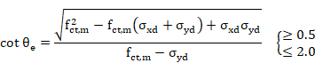
![]() reference angle of cracks inclination, obtained from:
reference angle of cracks inclination, obtained from:

![]() design normal stresses, at section gravity center, parallel to
the longitudinal axis of member and to the shear force
design normal stresses, at section gravity center, parallel to
the longitudinal axis of member and to the shear force ![]() respectively (tension positive)
respectively (tension positive)
Taking ![]()
In addition, the increment in tensile force due to shear force is calculated with the following equation:
![]()
For each end, calculated results are written in the CivilFEM results file:
VSU Contribution of the shear reinforcement to the shear strength.
![]()
VCU Contribution of concrete to the shear strength.
![]()
VU2 Ultimate shear strength for tension in the web.
![]()
CRTVU2 Ratio
of the design shear force (![]() ) to the resistance
) to the resistance ![]() .
.
![]()
If ![]() , the CTRVU2 criterion is taken as 2100.
, the CTRVU2 criterion is taken as 2100.
The tension increment due to shear force is stored in the CivilFEM results file as INCTENS.
8) Obtaining shear criterion. The shear criterion indicates whether the section is valid for the design forces (if it is less than 1, the section satisfies the code prescriptions; whereas if it exceeds 1, the section will not be valid). Furthermore, it includes information pertaining to how close the design force is to the ultimate section strength. The shear criterion is defined as follows:
![]()
For each element end, this value is stored in the CivilFEM results file as CRT_TOT.
The value 2100
for this criterion idicates that shear strength for tension in the web (![]() ) is equal to zero, as described in the previous step.
) is equal to zero, as described in the previous step.
11-B.2.2 Torsion Checking
The torsion checking according to EHE-98 follows the steps below:
1) Obtaining material strength properties. These properties are obtained from the material properties associated to each transverse cross section and for the active time, (see ~CFMP command).
The required data are the following:
![]() characteristic strength of concrete
characteristic strength of concrete
![]() characteristic yield strength of reinforcement
characteristic yield strength of reinforcement
![]() concrete partial safety factor
concrete partial safety factor
![]() reinforcement steel partial safety factor
reinforcement steel partial safety factor
2) Obtaining geometrical parameters depending on code. Geometrical parameters used for torsion calculations must be defined within CivilFEM database. The required data are the following ones:
![]() effective thickness, (parameter HE of ~SECMDF command).
effective thickness, (parameter HE of ~SECMDF command).
![]() area involved by the center-line of the effective hollow
section, (parameter AE of ~SECMDF command).
area involved by the center-line of the effective hollow
section, (parameter AE of ~SECMDF command).
![]() perimeter of the center-line of the effective hollow
section, (parameter UE of ~SECMDF command).
perimeter of the center-line of the effective hollow
section, (parameter UE of ~SECMDF command).
KEYAST indicator of the position of torsional reinforcement in the section, (KEYAST parameter of ~SECMDF command):
= 0 if closed stirrups are placed in both faces of the equivalent hollow section wall or of the real hollow section (value by default for hollow sections).
= 1 if there are closed stirrups only along the periphery of the member (value by default for solid sections).
q Angle of the compressive struts of concrete with the longitudinal axis of member, (parameter THETA of ~SECMDF command):
![]()
Section 11-A.7 “Previous Considerations to Shear and Torsion Calculation” provides detailed information on how to calculate the required data for each code and valid section.
3) Obtaining section reinforcement data. Data concerning reinforcements of the section must be included within CivilFEM database, (see ~RNFDEF and ~RNFMDF commands). Required data are the following:
Transverse Reinforcement
![]() area of transverse reinforcement per unit of length,
(parameter AST/S of ~RNFDEF or ~RNFMDF command).
area of transverse reinforcement per unit of length,
(parameter AST/S of ~RNFDEF or ~RNFMDF command).
The reinforcement ratio can also be obtained with the following data:
![]() closed stirrups area for torsion, (parameter AST of ~RNFDEF or ~RNFMDF
command).
closed stirrups area for torsion, (parameter AST of ~RNFDEF or ~RNFMDF
command).
s spacing of closed stirrups, (parameter ST of ~RNFDEF or ~RNFMDF command).
Or with the following data:
s spacing of closed stirrups, (parameter ST of ~RNFDEF or ~RNFMDF command).
![]() diameter of the closed stirrups bars, (parameter PHIT
of ~RNFDEF or ~RNFMDF
command).
diameter of the closed stirrups bars, (parameter PHIT
of ~RNFDEF or ~RNFMDF
command).
Longitudinal Reinforcement
![]() total area of the longitudinal reinforcement, (parameter
ASL of ~RNFDEF or ~RNFMDF
command).
total area of the longitudinal reinforcement, (parameter
ASL of ~RNFDEF or ~RNFMDF
command).
The reinforcement ratio can also be obtained with the following data:
f diameter of longitudinal bars, (parameter PHIL of ~RNFDEF or ~RNFMDF command).
N number of longitudinal bars, (parameter N of ~RNFDEF or ~RNFMDF command).
4) Obtaining section internal forces and moments. The torsional moment that acts on the section is obtained from the CivilFEM results file (.RCV).
Moment Description
![]() Design torsional moment in the section
Design torsional moment in the section
5) Checking failure by compression of concrete. First, a check is made to ensure the design torsional moment (![]() ) is less than or equal to the ultimate torsional moment for
compression in concrete (
) is less than or equal to the ultimate torsional moment for
compression in concrete (![]() ); as a result, the following condition must be satisfied:
); as a result, the following condition must be satisfied:
![]()
![]()
Where:
![]() design compressive strength of concrete
design compressive strength of concrete
![]()
a 1.20 if stirrups are only placed along the periphery of the member
1.50 if closed stirrups are placed at both faces of the wall of the effective or real hollow section.
Calculated results are stored in the CivilFEM results file as:
TU1 Maximum torsional moment that can be resisted by the section without crushing due to compression of concrete compressive struts.
![]()
CRTTU1 Ratio
of the design torsional moment (![]() ) to the resistance
) to the resistance ![]() .
.
![]()
6) Checking transverse reinforcement failure. The condition for tensile failure of the transverse reinforcement in
a section subjected to a torsional moment ![]() is:
is:
![]()
![]()
where:
![]() cross-sectional area of one of the bars used as
transverse torsional reinforcement.
cross-sectional area of one of the bars used as
transverse torsional reinforcement.
s spacing of closed stirrups of transverse torsional reinforcement.
![]() design yield strength of torsion reinforcement (
design yield strength of torsion reinforcement (![]() £ 400 N/mm2). The same steel type will be used for both
transverse and longitudinal torsion reinforcement.
£ 400 N/mm2). The same steel type will be used for both
transverse and longitudinal torsion reinforcement.
Calculated results are stored in the CivilFEM results file as:
TU2 Maximum torsional moment resisted by the section without failure due to tension of the transverse reinforcement.
![]()
CRTTU2 Ratio
of the design torsional moment (![]() ) to the resistance
) to the resistance ![]() .
.
![]()
If the torsion transverse reinforcement is not defined, the criterion is taken as 2100.
7) Checking longitudinal reinforcement failure. The condition for tensile failure of the longitudinal reinforcement
in a section subjected to a torsional moment ![]() is:
is:
![]()
![]()
Where ![]() is the area of the longitudinal torsion reinforcement.
is the area of the longitudinal torsion reinforcement.
Calculated results are stored in the CivilFEM results file as:
TU3 Maximum torsional moment resisted by the section without failure of the longitudinal reinforcement due to tension.
![]()
CRTTU3 Ratio
of the design torsional moment (![]() ) to the resistance
) to the resistance ![]() .
.
![]()
In the case the longitudinal reinforcement is not defined, the criterion is taken as 2100.
8) Obtaining torsion criterion. The torsion criterion indicates the ratio of the design moment to the section ultimate strength (if it is less than 1, the section is valid; whereas if it exceeds 1, the section is not valid). The criterion pertaining to the validity for torsion is defined as follows:
![]()
For each element end, this value is stored in the CivilFEM results file as CRT_TOT.
A value 2100 for this criterion indicates one of the torsion reinforcements has not been defined.
11-B.2.3 Combined Shear and Torsion Checking
Checking sections subjected to shear force and concomitant torsional moment follows the steps below:
1) Torsion checking considering a null shear force. This check follows the same steps as for the check of elements subjected to pure torsion according to EHE-98.
Except for this check, the CRT_TOT criterion is stored in the CivilFEM results file as CRTTRS for each element end.
2) Shear checking assuming a null torsional moment. Follows the same procedure as for the check of elements subject to pure shear according to EHE-98.
Except for this check, the CRT_TOT criterion is stored in the CivilFEM results file as CRTSHR for each element end.
3) Checking the condition of the ultimate compressive strength of concrete.
The design torsional moment (![]() ) and the design shear force (
) and the design shear force (![]() ) must satisfy the following condition:
) must satisfy the following condition:

Where:
![]()
![]() ultimate torsional moment for the compression failure of
concrete, calculated in step No. 1.
ultimate torsional moment for the compression failure of
concrete, calculated in step No. 1.
![]() ultimate shear force for the compression failure of
concrete, calculated in step No. 2.
ultimate shear force for the compression failure of
concrete, calculated in step No. 2.
For each element, this criterion value is stored in the CivilFEM results file as CRTCST.
4) Obtaining the combined shear and torsion criterion. This criterion considers pure shear, pure torsion and the ultimate strength condition of concrete. This criterion determines whether the section is valid and is defined as follows:

For each element, this criterion value is stored in the CivilFEM results file as CRT_TOT.
The value 2100 for this criterion indicates that one of the denominators is null, signifiying one of the reinforcements is not defined.
11-B.2.4 Shear Design
The shear designing according to EHE-98 follows these steps:
1) Obtaining material strength properties. These properties are obtained from the material properties associated to each transverse cross section and for the active time, (see ~CFMP command).
The required data are the following ones:
![]() characteristic strength of concrete.
characteristic strength of concrete.
![]() characteristic yield strength of reinforcement.
characteristic yield strength of reinforcement.
![]() mean tensile strength of concrete.
mean tensile strength of concrete.
![]() concrete safety factor.
concrete safety factor.
![]() steel safety factor.
steel safety factor.
2) Obtaining geometrical data of the section. Section geometrical requirements must be defined within CivilFEM database, (~CSECDMS command). Required data for shear design are the following:
![]() total area of the concrete section.
total area of the concrete section.
3) Obtaining geometrical parameters depending on specified code. Geometrical parameters used for shear designing must be defined within CivilFEM database, (see ~SECMDF command). Required data are the following ones:
![]() minimum width of the
section in a height equal to ¾ the effective depth, (parameter BW_VY or BW_VZ
of ~SECMDF command).
minimum width of the
section in a height equal to ¾ the effective depth, (parameter BW_VY or BW_VZ
of ~SECMDF command).
d effective depth of the section, (parameter D_Y or D_Z of ~SECMDF command).
![]() geometric ratio of the longitudinal tensile reinforcement
anchored at a distance greater than or equal to d from the considered section,
(parameter RHO1 of ~SECMDF command).
geometric ratio of the longitudinal tensile reinforcement
anchored at a distance greater than or equal to d from the considered section,
(parameter RHO1 of ~SECMDF command).
![]()
q angle of the concrete compressive struts with the member’s longitudinal axis, (parameter THETA of ~SECMDF command):
![]()
Section 11-A.7 “Previous Considerations to Shear and Torsion Calculation” provides detailed information on how to calculate the required data for each code and valid section.
4) Obtaining reinforcement data of the section. For the shear reinforcement design, it is possible to define the angle a between the reinforcement and the longitudinal axis of the member, (parameter ALPHA of ~RNFDEF or ~RNFMDF command). If this angle is null or is not defined, a=90º. Other reinforcement data are ignored.
5) Obtaining forces and moments acting on the section. The shear force that acts on the section as well as the concomitant axial force are obtained from the CivilFEM results file (.RCV).
Force Description
![]() Design shear force in Y
Design shear force in Y
![]() Design axial force
Design axial force
6) Checking for failure due to compression in the web. First, a check is made to ensure the design shear force (Vrd) is less than or equal to the oblique compression resistance of concrete in the web (Vu1):
![]()
![]()
where:
![]() design compressive strength of concrete
design compressive strength of concrete
![]()
K reduction coefficient by axial force effect

![]() effective axial stress in the section (tension positive)
effective axial stress in the section (tension positive)
![]()
For each element end, calculated results are written in the CivilFEM results file as:
VU1 Ultimate shear strength due to oblique compression of the concrete in web.
![]()
CRTVU1 Ratio
of the design shear force (![]() ) to the resistance
) to the resistance ![]() .
.
![]()
If design shear force is greater than shear force that causes the failure due to oblique compression of concrete in the web, the reinforcement design will not be feasible. Then, the parameter where the reinforcement will be stored as 2100.
![]()
In this case, the element is labeled as not designed; the program then advances to the next element.
In case there is no failure due to oblique compression, the calculation process continues.
7) Checking if section requires shear reinforcement. First, a check is made to ensure the design shear force ![]() is less than the strength provided by the concrete in members
without shear reinforcement (
is less than the strength provided by the concrete in members
without shear reinforcement (![]() ):
):
![]()
![]()
where:
![]() , d in mm
, d in mm
If the section does not require shear reinforcement, the following parameters are defined (for both element ends):
![]()
![]()
![]()
![]()
If the section requires shear reinforcement, the calculation process continues.
8) Determining the contribution of the required transverse reinforcement to the shear strength. If the section requires shear reinforcement, the condition concerning the validity for sections under shear force is the following:
![]()
![]()
![]() contribution of shear
transverse reinforcement in the web to shear strength.
contribution of shear
transverse reinforcement in the web to shear strength.
![]() contribution of concrete to shear strength.
contribution of concrete to shear strength.
![]()
where:

![]() reference angle of cracks inclination, obtained from the
following expression:
reference angle of cracks inclination, obtained from the
following expression:

![]() design normal stresses, at the center of gravity of the section,
parallel to the longitudinal axis of the member and to the shear force
design normal stresses, at the center of gravity of the section,
parallel to the longitudinal axis of the member and to the shear force ![]() respectively (tension positive)
respectively (tension positive)
Taking ![]()
Therefore, the shear reinforcement contribution is given by the equation below:
![]()
For each element
end, the value of ![]() and
and ![]() is stored in the CivilFEM results
file:
is stored in the CivilFEM results
file:
![]()
9) Required reinforcement ratio. Once the shear force that must be carried by the shear reinforcement has been obtained, this can be calculated from the equation below:

Where:
![]() cross-sectional area of the designed shear reinforcement
per unit length.
cross-sectional area of the designed shear reinforcement
per unit length.
The area of designed reinforcement per unit length is stored in the CivilFEM results file for both ends:
![]()
In this case the element is marked as designed (provided that the design process is correct for both element sections).
11-B.2.5 Torsion Design
Torsion reinforcement design according to EHE-98 follows the following steps:
1) Obtaining material strength properties. These properties are obtained from the material properties associated to each transverse cross section and for the active time, (see ~CFMP command).
The required data are the following ones:
![]() characteristic strength of concrete
characteristic strength of concrete
![]() characteristic yield strength of reinforcement
characteristic yield strength of reinforcement
![]() concrete partial safety factor
concrete partial safety factor
![]() reinforcement partial safety factor
reinforcement partial safety factor
2) Obtaining geometrical parameters depending on specified code. Geometrical parameters utilized used for torsion design must be defined for each code at member level according to chapter 5 of this manual. The required data are the following:
![]() area enclosed by the center-line of the effective hollow
section, (parameter AE of ~SECMDF command).
area enclosed by the center-line of the effective hollow
section, (parameter AE of ~SECMDF command).
![]() perimeter of the center-line of the effective hollow
section, (parameter UE of ~SECMDF command).
perimeter of the center-line of the effective hollow
section, (parameter UE of ~SECMDF command).
KEYAST indicator of the position of the torsion reinforcement in the section, (parameter KEYAST of ~SECMDF command).
=0 if closed stirrups are placed in both faces of the equivalent hollow section wall or of the real hollow section (value by default for hollow sections).
=1 if closed stirrups are only placed along the periphery of the member (value by default for solid sections).
q angle of the concrete compressive struts with the longitudinal axis of member, (parameter THETA of ~SECMDF command):
![]()
Section 11-A.7 “Previous Considerations to Shear and Torsion Calculation” provides detailed information on how to calculate the required data for each code and valid section.
3) Obtaining forces and moments acting on the section. The torsional moment that acts on the section is obtained from the CivilFEM results file (.RCV).
Moment Description
![]() Design torsional moment
Design torsional moment
4) Checking compression failure of concrete. First, a check is made to ensure the design torsional moment (![]() ) is less than or equal to the ultimate torsional moment due to
compression in concrete (
) is less than or equal to the ultimate torsional moment due to
compression in concrete (![]() ); therefore, the following condition must be satisfied:
); therefore, the following condition must be satisfied:
![]()
![]()
where:
![]() concrete compressive strength
concrete compressive strength
![]()
a 1.20 if stirrups are only placed along the periphery of the member.
1.50 if closed stirrups are placed at both faces of the wall of the effective hollow section or of the real hollow section.
Calculated results are stored in the CivilFEM results file:
TU1 Maximum torsional moment resisted by the section without crushing due to compression of concrete compressive struts.
![]()
CRTTU1 Ratio
of the design torsional moment (![]() ) to the resistance
) to the resistance ![]() .
.
![]()
If the design torsional moment is greater than the moment that causes compression failure of the concrete, the reinforcement design will not be feasible. Therefore, the parameters where the reinforcement data are stored are defined as 2100.
![]() for transverse reinforcement
for transverse reinforcement
![]() for longitudinal reinforcement
for longitudinal reinforcement
In this case, the element is labeled as not designed, and the program will then advance to the next element.
If there is no failure due to oblique compression, the calculation process continues.
5) Calculating the transverse reinforcement required. The ultimate strength condition of the transverse reinforcement is:
![]()
where:
![]() area of the section of one of the bars used as
transverse reinforcement for torsion.
area of the section of one of the bars used as
transverse reinforcement for torsion.
s spacing of the closed stirrups of the transverse reinforcement for torsion.
Therefore, the required transverse reinforcement is:

The area per unit length of the designed transverse reinforcement is stored in the CivilFEM results file for both element ends as:
![]()
6) Calculating the longitudinal reinforcement required. The ultimate strength condition of the longitudinal reinforcement is:
Where ![]() is the area of the torsional longitudinal reinforcement.
is the area of the torsional longitudinal reinforcement.
Consequently, the longitudinal reinforcement required is:
The area of the designed longitudinal reinforcement is stored in the CivilFEM results file for both element ends as:
![]()
If design for both element sections is done for both transverse and longitudinal reinforcements, the element will be labeled as designed.
11-B.2.6 Combined Shear and Torsion Design
The design of sections subjected to shear force and concomitant torsional moment follows the steps below:
1) Torsion design considering a null shear force. This design follows the same steps as for the design of elements subjected to pure torsion according to EHE-98.
2) Shear design assuming a null torsional moment. This design is accomplished with the same procedure as for the design of elements only subjected to shear force according to EHE-98.
3) Checking the failure condition by compression in the concrete.
The design torsional moment (![]() ) and the design shear force (
) and the design shear force (![]() ) must to satisfy the following condition:
) must to satisfy the following condition:
where:
![]()
![]() ultimate torsional moment due to compression of concrete,
calculated in step No. 1.
ultimate torsional moment due to compression of concrete,
calculated in step No. 1.
![]() ultimate shear strength due to compression of concrete,
calculated in step No 2.
ultimate shear strength due to compression of concrete,
calculated in step No 2.
For each element end, this criterion value is stored in the CivilFEM results file as CRTCST.
4) Obtaining required shear and torsion reinforcement ratios. If the concrete ultimate strength condition is satisfied (i.e. the concrete can resist the combined shear and torsion action), the reinforcements calculated in steps No. 1 and No. 2 are taken as the designed reinforcements. The element will be labeled as designed.
If the concrete ultimate strength condition is not satisfied, the parameters corresponding to each reinforcement group take the value of 2100.
11-B.3 Shear and Torsion according to EHE-08
11-B.3.1 Shear Checking
The checking for shear according to EHE-08 follows the steps below:
1) Obtaining material strength properties. These properties are obtained from the material properties associated to each transverse cross section and for the active time.
The required data are the following:
![]() characteristic compressive strength of concrete.
characteristic compressive strength of concrete.
![]() characteristic yield strength of reinforcement.
characteristic yield strength of reinforcement.
![]() mean tensile strength of concrete.
mean tensile strength of concrete.
![]() characteristic tensile strength of concrete (fctk_005).
characteristic tensile strength of concrete (fctk_005).
![]() concrete partial safety factor.
concrete partial safety factor.
![]() steel partial safety factor.
steel partial safety factor.
2) Obtaining section geometrical data. Section geometrical requirements must be defined within CivilFEM database, (~CSECDMS commands). Required data for shear checking are the following:
![]() total area of the concrete section.
total area of the concrete section.
3) Obtaining geometrical parameters depending on specified code. Geometrical parameters used for shear calculations must be defined within CivilFEM database, (see ~SECMDF command). Required data are the following ones:
![]() Width of element in VY
direction equal to the total width in solid sections or in case of box sections,
the width equals the sum of the width of both webs. (parameter BW_VY or BW_VZ
of ~SECMDF command).
Width of element in VY
direction equal to the total width in solid sections or in case of box sections,
the width equals the sum of the width of both webs. (parameter BW_VY or BW_VZ
of ~SECMDF command).
d effective depth of the section, (parameter D_Y or D_Z of ~SECMDF command).
![]() geometric ratio of the tensile longitudinal
reinforcement anchored at a distance greater than or equal to d from the
considered section, (parameter RHO1 of ~SECMDF
command):
geometric ratio of the tensile longitudinal
reinforcement anchored at a distance greater than or equal to d from the
considered section, (parameter RHO1 of ~SECMDF
command):
![]()
q angle of the concrete compressive struts with the longitudinal axis of member, (parameter THETA of ~SECMDF command):
![]()
Section 11-A.7 “Previous Considerations to Shear and Torsion Calculation” provides detailed information on how to calculate the required data for each code and valid section.
4) Obtaining reinforcement data of the section. Data concerning reinforcements of the section must be included within CivilFEM database, (see ~RNFDEF and ~RNFMDF commands). Required data are the following ones:
a angle between shear reinforcement and the longitudinal axis of the member, (parameter ALPHA of ~RNFDEF or ~RNFMDF command).
![]() area of reinforcement per unit length, (parameter AS/S of ~RNFDEF or ~RNFMDF
command).
area of reinforcement per unit length, (parameter AS/S of ~RNFDEF or ~RNFMDF
command).
The reinforcement ratio may also be obtained with the following data:
![]() total area of the reinforcement legs, (parameter AS of ~RNFDEF or ~RNFMDF
command).
total area of the reinforcement legs, (parameter AS of ~RNFDEF or ~RNFMDF
command).
s spacing of the stirrups, (parameter S of ~RNFDEF or ~RNFMDF command).
Or with the data below:
s spacing of the stirrups, (parameter S of ~RNFDEF or ~RNFMDF command).
f diameter of bars, (parameter PHI of ~RNFDEF or ~RNFMDF command).
N number of reinforcement legs, (parameter N of ~RNFDEF or ~RNFMDF command).
5) Obtaining forces and moments acting on the section. The shear force that acts on the section, as well as the concomitant axial force and bending moment, are obtained from the CivilFEM results file (.RCV).
Force Description
![]() Design shear force in Y
Design shear force in Y
![]() Axial force
Axial force
6) Checking failure by compression in the web. First, a check is made to ensure the design shear force (![]() ) is less than or equal to the oblique compression resistance of
concrete in the web (
) is less than or equal to the oblique compression resistance of
concrete in the web (![]() ):
):
![]()
![]()
where:
![]() design compressive strength of concrete.
design compressive strength of concrete.

K reduction factor by axial forces effect

![]() effective axial stress in concrete (compression positive)
considering the axial stress taken by compressed reinforcement.
effective axial stress in concrete (compression positive)
considering the axial stress taken by compressed reinforcement.
For each element end, calculated results are written in the CivilFEM results file:
VU1 Ultimate shear strength due to oblique compression of the concrete in web.
![]()
CRTVU1 Ratio
of the design shear (Vrd) to the resistance ![]() .
.
![]()
7) Checking failure by tension in the web. A check is made to ensure the design shear force (Vrd)
is less than or equal to the shear force due to tension in the web (![]() ):
):
![]()
![]()
![]() contribution of web
shear transverse reinforcement to the shear strength.
contribution of web
shear transverse reinforcement to the shear strength.
![]() contribution of concrete to the shear strength.
contribution of concrete to the shear strength.
Members without shear reinforcement
If shear reinforcement has not been defined:
![]()

where:
![]()
![]() , d in mm
, d in mm
![]() limited to 60 MPa
limited to 60 MPa
Members with shear reinforcement
If shear reinforcement has been defined:
![]()
where:
![]() shear reinforcement area per unit of length
shear reinforcement area per unit of length
![]() design strength of reinforcement
design strength of reinforcement ![]()
In this case, the concrete contribution to shear strength is:
![]()
where:
![]()
![]()
![]() reference angle of cracks inclination, obtained from:
reference angle of cracks inclination, obtained from:

![]() ,
, ![]() design normal stresses, at the section’s center of gravity,
parallel to the longitudinal axis of member and the shear force
design normal stresses, at the section’s center of gravity,
parallel to the longitudinal axis of member and the shear force ![]() respectively (tension positive)
respectively (tension positive)
Taking ![]() à
à ![]()
In addition, the increment in tensile force due to shear force is calculated with the following equation:
![]()
For each end, calculated results are written in the CivilFEM results file as:
VSU Contribution of the shear reinforcement to the shear strength.
![]()
VCU Contribution of concrete to the shear strength.
![]()
VU2 Ultimate shear strength by tension in the web.
![]() =
=![]()
CRTVU2 Ratio
of the design shear force ![]() to the resistance
to the resistance ![]() .
.
![]()
If ![]() , the CTRVU2 criterion is taken as 2100.
, the CTRVU2 criterion is taken as 2100.
The tension increment due to shear force is stored in the CivilFEM results file as INCTENS.
8) Obtaining shear criterion. The shear criterion indicates whether the section is valid or not for the design forces (if it is less than 1, the section satisfies the code provisions; whereas if it exceeds 1, the section will not be valid). Furthermore, it includes information about how close the design force is to the ultimate section strength. The shear criterion is defined as follows:
![]()
For each element end, this value is stored in the CivilFEM results file as CRT_TOT.
A value 2100 for this criterion
indicates that the shear strength for tension in the web (![]() ) is equal to zero, as was described in the previous step.
) is equal to zero, as was described in the previous step.
11-B.3.2 Torsion Checking
The torsion checking according to EHE-08 follows the steps below:
1) Obtaining material strength properties. These properties are obtained from the material properties associated to each transverse cross section and for the active time, (see ~CFMP command).
The required data are the following:
![]() characteristic strength of concrete
characteristic strength of concrete
![]() characteristic yield strength of reinforcement
characteristic yield strength of reinforcement
![]() concrete partial safety factor
concrete partial safety factor
![]() reinforcement steel partial safety factor
reinforcement steel partial safety factor
2) Obtaining geometrical parameters depending on specified code. Geometrical parameters used for torsion calculations must be defined within CivilFEM database. The required data are the following:
![]() effective thickness, (parameter HE of ~SECMDF command).
effective thickness, (parameter HE of ~SECMDF command).
![]() area enclosed by the center-line of the effective
hollow section, (parameter AE of ~SECMDF
command).
area enclosed by the center-line of the effective
hollow section, (parameter AE of ~SECMDF
command).
![]() perimeter of the center-line of the effective hollow
section, (parameter UE of ~SECMDF command).
perimeter of the center-line of the effective hollow
section, (parameter UE of ~SECMDF command).
KEYAST indicator of the position of torsional reinforcement in the section, (KEYAST parameter of ~SECMDF command):
= 0 if closed stirrups are placed in both faces of the equivalent hollow section wall or of the real hollow section (value by default for hollow sections).
= 1 if there are closed stirrups only along the periphery of the member (value by default for solid sections).
q Angle of the compressive struts of concrete with the longitudinal axis of member, (parameter THETA of ~SECMDF command):
![]()
Section 11-A.7 “Previous Considerations to Shear and Torsion Calculation” provides detailed information on how to calculate the required data for each code and valid section.
3) Obtaining section reinforcement data. Data concerning reinforcements of the section must be included within CivilFEM database, (see ~RNFDEF and ~RNFMDF commands). Required data are the following:
Transverse Reinforcement
![]() area of transverse reinforcement per unit of length,
(parameter AST/S of ~RNFDEF or ~RNFMDF command).
area of transverse reinforcement per unit of length,
(parameter AST/S of ~RNFDEF or ~RNFMDF command).
The reinforcement ratio can also be obtained with the following data:
![]() closed stirrups area for torsion, (parameter AST of ~RNFDEF or ~RNFMDF
command).
closed stirrups area for torsion, (parameter AST of ~RNFDEF or ~RNFMDF
command).
s spacing of closed stirrups, (parameter ST of ~RNFDEF or ~RNFMDF command).
Or with the data below:
s spacing of closed stirrups, (parameter ST of ~RNFDEF or ~RNFMDF command).
![]() diameter of the closed stirrups bars, (parameter PHIT of
~RNFDEF or ~RNFMDF
command).
diameter of the closed stirrups bars, (parameter PHIT of
~RNFDEF or ~RNFMDF
command).
Longitudinal Reinforcement
![]() total area of the longitudinal reinforcement, (parameter
ASL of ~RNFDEF or ~RNFMDF
command).
total area of the longitudinal reinforcement, (parameter
ASL of ~RNFDEF or ~RNFMDF
command).
The reinforcement ratio can also be obtained with the following data:
![]() diameter of longitudinal bars, (parameter PHIL of ~RNFDEF or ~RNFMDF
command).
diameter of longitudinal bars, (parameter PHIL of ~RNFDEF or ~RNFMDF
command).
N number of longitudinal bars, (parameter N of ~RNFDEF or ~RNFMDF command).
4) Obtaining the section’s internal forces and moments. The torsional moment that acts on the section is obtained from the CivilFEM results file (.RCV).
Moment Description
![]() Design torsional moment in the section
Design torsional moment in the section
5) Checking compression failure of concrete. First, a check is made to ensure the design torsional moment (![]() ) is less than or equal to the ultimate torsional moment due to
compression in the concrete (
) is less than or equal to the ultimate torsional moment due to
compression in the concrete (![]() ); as a result, the following condition must be satisfied:
); as a result, the following condition must be satisfied:
![]()
![]()
Where:
![]() design compressive strength of concrete
design compressive strength of concrete

K reduction factor by axial forces effect

a 0.60 if only there are stirrups along the periphery of the member;
0.75 if closed stirrups are placed at both faces of the wall of the effective hollow section or real hollow section.
Calculated results are stored in the CivilFEM results file as:
TU1 Maximum torsional moment that can be resisted by the section without crushing due to compression of concrete compressive struts.
![]()
CRTTU1 Ratio
of the design torsional moment (![]() ) to the resistance
) to the resistance ![]() .
.
![]()
6) Checking transverse reinforcement failure. The tensile failure condition of the transverse reinforcement in a
section subjected to a torsional moment ![]() is:
is:
![]()
![]()
where:
![]() cross-sectional area of one of the bars used as
transverse torsional reinforcement.
cross-sectional area of one of the bars used as
transverse torsional reinforcement.
s spacing of closed stirrups of transverse torsional reinforcement.
![]() design yield strength of torsion reinforcement (
design yield strength of torsion reinforcement (![]() £ 400 N/mm2). The same steel type will be used for both
transverse and longitudinal torsion reinforcement.
£ 400 N/mm2). The same steel type will be used for both
transverse and longitudinal torsion reinforcement.
Calculated results are stored in the CivilFEM results file as:
TU2 Maximum torsional moment resisted by the section so without causing failure in the transverse reinforcement due to tension.
![]()
CRTTU2 Ratio
of the design torsional moment (![]() ) to the resistance
) to the resistance ![]() .
.
![]()
If the torsion transverse reinforcement is not defined, the criterion is taken as 2100.
7) Checking longitudinal reinforcement failure. The tensile failure condition of the longitudinal reinforcement in
a section subjected to a torsional moment ![]() is:
is:
![]()
![]()
Where ![]() is the area of the longitudinal torsion reinforcement.
is the area of the longitudinal torsion reinforcement.
Calculated results are stored in the CivilFEM results file as:
TU3 Maximum torsional moment resisted by the section without causing tensile failure in the longitudinal reinforcement.
![]()
CRTTU3 Ratio of the design torsional moment (Td) to the resistance Tu3.
![]()
In the case the longitudinal reinforcement is not defined, the criterion is taken as 2100.
8) Obtaining torsion criterion. The torsion criterion identifies the ratio of the design moment to the section’s ultimate strength (if it is less than 1, the section is valid; whereas if it exceeds 1, the section is not valid). The criterion concerning the validity for torsion is defined as follows:
![]()
For each element end, this value is stored in the CivilFEM results file as CRT_TOT.
A value 2100 for this criterion indicates that any one of the torsion reinforcements are not defined.
11-B.3.3 Combined Shear and Torsion Checking
Checking sections subjected to shear force and concomitant torsional moment follows the steps below:
1) Torsion checking considering a null shear force. This check is accomplished with the same steps as for the check of elements subjected to pure torsion according to EHE-08.
For each element end, this value is stored in the CivilFEM results file as CRTTRS.
2) Shear checking assuming a null torsional moment. Follows the same procedure as for the check of elements only subjected to shear according to EHE-08.
For each element end, this value is stored in the CivilFEM results file as CRTSHR.
3) Checking the ultimate compressive strength condition of concrete. The design torsional moment (![]() ) and the design shear force (
) and the design shear force (![]() ) must satisfy the following condition:
) must satisfy the following condition:
Where:
![]()
![]() ultimate torsional moment due to compression of concrete,
calculated in step No. 1.
ultimate torsional moment due to compression of concrete,
calculated in step No. 1.
![]() ultimate shear force by compression of concrete,
calculated in step No. 2.
ultimate shear force by compression of concrete,
calculated in step No. 2.
For each element, this criterion value is stored in the CivilFEM results file as CRTCST.
4) Obtaining the combined shear and torsion criterion. This criterion comprehends pure shear, pure torsion and concrete ultimate strength condition criteria. The criterion determines whether the section is valid or not, and it is defined as follows:

For each element, this criterion value is stored in the CivilFEM results file as CRT_TOT.
A value 2100 for this criterion indicates that one of the denominators is null, because one of the reinforcements is not defined.
11-B.3.4 Shear Design
The shear designing according to EHE-08 follows these steps:
1) Obtaining material strength properties. These properties are obtained from the material properties associated to each transverse cross section and for the active time, (see ~CFMP command).
The required data are the following ones:
![]() characteristic strength of concrete.
characteristic strength of concrete.
![]() characteristic yield strength of reinforcement.
characteristic yield strength of reinforcement.
![]() mean tensile strength of concrete.
mean tensile strength of concrete.
![]() concrete safety factor.
concrete safety factor.
![]() steel safety factor.
steel safety factor.
2) Obtaining geometrical data of the section. Section geometrical requirements must be defined within CivilFEM database, (~CSECDMS command). Required data for shear design are the following:
![]() total area of the concrete section.
total area of the concrete section.
3) Obtaining geometrical parameters depending on specified code. Geometrical parameters used for shear design must be defined within the CivilFEM database, (see ~SECMDF command). Required data are the following ones:
![]() minimum width of the
section in a height equal to ¾ the effective depth, (parameter BW_VY or BW_VZ
of ~SECMDF command).
minimum width of the
section in a height equal to ¾ the effective depth, (parameter BW_VY or BW_VZ
of ~SECMDF command).
d effective depth of the section, (parameter D_Y or D_Z of ~SECMDF command).
![]() geometric ratio of the tension longitudinal
reinforcement anchored at a distance greater than or equal to d from the
considered section, (parameter RHO1 of ~SECMDF
command).
geometric ratio of the tension longitudinal
reinforcement anchored at a distance greater than or equal to d from the
considered section, (parameter RHO1 of ~SECMDF
command).
![]()
q angle of the concrete compressive struts with the longitudinal axis of member, (parameter THETA of ~SECMDF command):
![]()
Section 11-A.7 “Previous Considerations to Shear and Torsion Calculation” provides detailed information on how to calculate the required data for each code and valid section.
4) Obtaining reinforcement data of the section. In the shear reinforcement design, it is possible to define the angle a between the reinforcement and the longitudinal axis of the member, (parameter ALPHA of ~RNFDEF or ~RNFMDF command). If this angle is null or it is not defined, a=90º. Other reinforcement data are ignored.
5) Obtaining forces and moments acting on the section. The shear force that acts on the section as well as the concomitant axial force are obtained from the CivilFEM results file (.RCV).
Force Description
![]() Design shear force in Y
Design shear force in Y
![]() Design axial force
Design axial force
6) Checking compression failure in the web. First, a check is made to ensure the design shear force (![]() ) is less than or equal to the oblique compression resistance of
concrete in the web (
) is less than or equal to the oblique compression resistance of
concrete in the web (![]() ):
):
![]()
![]()
where:
![]() design compressive strength of concrete
design compressive strength of concrete
K reduction factor by axial forces effect
![]() effective axial stress in concrete (compression positive)
considering the axial stress taken by reinforcement in compression.
effective axial stress in concrete (compression positive)
considering the axial stress taken by reinforcement in compression.
For each element end, calculated results are written in the CivilFEM results file as:
VU1 Ultimate shear strength due to oblique compression of the concrete in web.
![]()
CRTVU1 Ratio
of the design shear force (![]() ) to the resistance
) to the resistance ![]() .
.
![]()
If the design shear force is greater than the shear force that causes failure due to oblique compression in the concrete of the web, the reinforcement design will not be feasible. The parameter where the reinforcement data is stored will be defined as 2100.
![]()
In this case, the element is labeled as not designed, and the program then advances to next element.
In the case there is no failure due to oblique compression, the calculation process continues.
7) Checking if section requires shear reinforcement. First, a check is made to ensure the design shear force ![]() is less than the strength provided by the concrete in members
without shear reinforcement (
is less than the strength provided by the concrete in members
without shear reinforcement (![]() ):
):
![]()

where:
![]() (Compression positive)
(Compression positive)
![]() , d in mm
, d in mm
![]() limited to 60 MPa
limited to 60 MPa
If the section does not require shear reinforcement, the following parameters are defined (for both element ends):
![]()
![]()
![]()
![]()
If section requires shear reinforcement, the calculation process continues.
8) Determining the contribution of the required transverse reinforcement to the shear strength. If the section requires shear reinforcement, the condition for the validity of the sections under shear force is the following:
![]()
![]()
![]() contribution of transverse
shear reinforcement in the web to the shear strength.
contribution of transverse
shear reinforcement in the web to the shear strength.
![]() contribution of concrete to the shear strength.
contribution of concrete to the shear strength.
![]()
where:
![]()
![]()
![]() reference angle of cracks inclination, obtained from the
following expression:
reference angle of cracks inclination, obtained from the
following expression:
![]() ,
, ![]() design normal stresses, at the center of gravity of the section,
parallel to the longitudinal axis of the member or to the shear force
design normal stresses, at the center of gravity of the section,
parallel to the longitudinal axis of the member or to the shear force ![]() , respectively (tension positive)
, respectively (tension positive)
Taking ![]()
Therefore, the shear reinforcement contribution is given by:
![]()
For each element end, the value of Vcu and Vsu is stored in the CivilFEM results file:
![]()
![]()
9) Required reinforcement ratio. Once the required shear strength of the shear reinforcement has been obtained, the reinforcement ratio can be calculated from the equation below:
![]()
Where:
![]() cross-sectional area of the designed shear reinforcement
per unit length.
cross-sectional area of the designed shear reinforcement
per unit length.
The area of the designed reinforcement per unit length is stored in the CivilFEM results file for both ends:
![]()
In this case, the element is labeled as designed (provided that the design process is correct for both element sections).
11-B.3.5 Torsion Design
Torsion reinforcement design according to EHE-08 follows the following steps:
1) Obtaining material strength properties. These properties are obtained from the material properties associated to each transverse cross section and for the active time, (see ~CFMP command).
The required data are the following ones:
![]() characteristic strength of concrete
characteristic strength of concrete
![]() characteristic yield strength of reinforcement
characteristic yield strength of reinforcement
![]() concrete partial safety factor
concrete partial safety factor
![]() reinforcement partial safety factor
reinforcement partial safety factor
2) Obtaining geometrical parameters depending on specified code. Geometrical parameters utilized used for torsion design must be defined for each code at member level according to chapter 5 of this manual. The required data are the following ones:
![]() area enclosed by the center-line of the effective hollow
section, (parameter AE of ~SECMDF command).
area enclosed by the center-line of the effective hollow
section, (parameter AE of ~SECMDF command).
![]() perimeter of the center-line of the effective hollow
section, (parameter UE of ~SECMDF command).
perimeter of the center-line of the effective hollow
section, (parameter UE of ~SECMDF command).
KEYAST indicator of the position of the torsion reinforcement in the section, (parameter KEYAST of ~SECMDF command).
= 0 if closed stirrups are placed in both faces of the equivalent hollow section wall or of the real hollow section (value by default for hollow sections).
= 1 if closed stirrups are only placed along the periphery of the member (value by default for solid sections).
q angle of the concrete compressive struts with the longitudinal axis of member, (parameter THETA of ~SECMDF command):
![]()
Section 11-A.7 “Previous Considerations to Shear and Torsion Calculation” provides detailed information on how to calculate the required data for each code and valid section.
3) Obtaining forces and moments acting on the section. The torsional moment that acts on the section is obtained from the CivilFEM results file (.RCV).
Moment Description
![]() Design torsional moment
Design torsional moment
4) Checking compression failure of concrete. First, a check is made to ensure the design torsional moment (![]() ) is less than or equal to the ultimate torsional moment for
compression in concrete (
) is less than or equal to the ultimate torsional moment for
compression in concrete (![]() ); therefore, the following condition must be satisfied:
); therefore, the following condition must be satisfied:
![]()
![]()
where:
![]() concrete compressive strength
concrete compressive strength
K reduction factor by axial forces effect

a 1.20 if stirrups are only placed along the periphery of the member.
1.50 if closed stirrups are placed at both faces of the wall of the effective hollow section or of the real hollow section.
Calculated results are stored in the CivilFEM results file:
TU1 Maximum torsional moment resisted by the section without causing crushing due to compression of concrete compressive struts.
![]()
CRTTU1 Ratio
of the design torsional moment (![]() ) to the resistance
) to the resistance ![]() .
.
![]()
If design torsional moment is greater than the torsional moment that causes the compression failure of concrete, the reinforcement design will not be feasible. Therefore, the parameters for the reinforcement data will be defined as 2100.
![]() for transverse reinforcement
for transverse reinforcement
![]() for longitudinal reinforcement
for longitudinal reinforcement
In this case, the element is labeled as not designed, and the program then advances to the next element.
In the case there is no failure due to oblique compression, the calculation process continues.
5) Calculating the transverse reinforcement required. The ultimate strength condition of the transverse reinforcement is:
![]()
where:
![]() area of the section of one of the bars used as
transverse reinforcement for torsion.
area of the section of one of the bars used as
transverse reinforcement for torsion.
s spacing of the closed stirrups of the transverse reinforcement for torsion.
Therefore, the required transverse reinforcement is:

The area per unit length of the designed transverse reinforcement is stored in the CivilFEM results file for both element ends as:
![]()
6) Calculating the longitudinal reinforcement required. The ultimate strength condition of the longitudinal reinforcement is:
![]()
Where ![]() is the area of the torsional longitudinal reinforcement.
is the area of the torsional longitudinal reinforcement.
Consequently, the longitudinal reinforcement required is:

The area of the designed longitudinal reinforcement is stored in the CivilFEM results file for both element ends as:
![]()
If design for both element sections is done for both transverse and longitudinal reinforcements, and the element will be labeled as designed.
11-B.3.6 Combined Shear and Torsion Design
The design of sections subjected to shear force and concomitant torsional moment follows the steps below:
1) Torsion design considering a null shear force. This design is accomplished with the same steps as for the design of elements subjected to pure torsion according to EHE-08.
2) Shear design assuming a null torsional moment. This design follows the same procedure as for the design of elements only subjected to shear force according to EHE-08.
3) Checking the failure condition by compression in the concrete. The design torsional moment (Td) and the design shear force (Vrd) must to satisfy the following condition:
where:
![]()
![]() ultimate torsional moment due to compression of concrete,
calculated in step 1.
ultimate torsional moment due to compression of concrete,
calculated in step 1.
![]() ultimate shear strength due to compression of concrete,
calculated in step 2.
ultimate shear strength due to compression of concrete,
calculated in step 2.
For each element end, this criterion value is stored in the CivilFEM results file as CRTCST.
4) Obtaining required shear and torsion reinforcement ratios. If the concrete ultimate strength condition is satisfied (i.e. the concrete can resist the combined shear and torsion action), the reinforcements calculated in steps 1 and 2 are taken as the designed reinforcements. The element will be labeled as designed.
If the concrete ultimate strength condition is not satisfied, the parameters corresponding to each reinforcement group will take the value 2100.
11-B.4 Shear and Torsion according to BS8110
11-B.4.1 Shear Checking
1) Obtaining material strength properties. These properties are obtained from the material properties associated to each transverse cross section and for the active time (see command ~CFMP).
The required data are the following:
![]() characteristic compressive strength of concrete.
characteristic compressive strength of concrete.
![]() characteristic
yield strength of reinforcement.
characteristic
yield strength of reinforcement.
![]() concrete partial safety factor.
concrete partial safety factor.
2) Obtaining geometrical data of the section. Section geometrical requirements must be defined within CivilFEM database, (~CSECDMS commands). Required data for shear checking are the following:
![]() total area of the concrete transverse section.
total area of the concrete transverse section.
h total depth in the shear direction considered.
3) Obtaining geometrical parameters depending on specified code. Geometrical parameters used for shear calculations must be defined within CivilFEM database, (see ~SECMDF command). Required data are the following ones:
![]() minimum width of the
section, (parameter BW_VY or BW_VZ of ~SECMDF
command).
minimum width of the
section, (parameter BW_VY or BW_VZ of ~SECMDF
command).
d effective depth of the section, (parameter D_Y or D_Z of ~SECMDF command).
![]() Area of the longitudinal tension reinforcement that
extends at least a distance d beyond the considered section.
Area of the longitudinal tension reinforcement that
extends at least a distance d beyond the considered section.
Section 11-A.7 “Previous Considerations to Shear and Torsion Calculation” provides detailed information on how to calculate the required data for each code and valid section.
4) Obtaining reinforcement data of the section. Data concerning reinforcements of the section must be included within CivilFEM database, (see ~RNFDEF and ~RNFMDF commands). Required data are the following:
a angle between shear reinforcement and the longitudinal axis of the member. For this code, a = 90º.
![]() area of reinforcement per unit length, (parameter AS/S of ~RNFDEF or ~RNFMDF
command).
area of reinforcement per unit length, (parameter AS/S of ~RNFDEF or ~RNFMDF
command).
The reinforcement ratio may also be obtained with the following data:
![]() total area of the reinforcement legs, (parameter AS of ~RNFDEF or ~RNFMDF
command).
total area of the reinforcement legs, (parameter AS of ~RNFDEF or ~RNFMDF
command).
s spacing of the stirrups, (parameter S of ~RNFDEF or ~RNFMDF command).
Or with the data below:
s spacing of the stirrups, (parameter S of ~RNFDEF or ~RNFMDF command).
f diameter of bars, (parameter PHI of ~RNFDEF or ~RNFMDF command).
N number of reinforcement legs, (parameter N of ~RNFDEF or ~RNFMDF command).
5) Obtaining forces and moments acting on the section. The shear force that acts on the section as well as the concomitant axial force and bending moment are obtained from the CivilFEM results file (.RCV).
Force Description
![]() Design shear force
Design shear force
![]() Concomitant axial force
Concomitant axial force
M Concomitant bending moment
6)
Checking compression failure in the web. First, a
check is made to ensure the design shear force (![]() ) is less than or equal to the oblique compression resistance of
concrete section (
) is less than or equal to the oblique compression resistance of
concrete section (![]() ):
):
![]()
![]()
For each element end, calculated results are written in the CivilFEM results file in the following parameters:
VU1 Ultimate shear strength due to oblique compression of the concrete in web.
![]()
CRTVU1 Ratio
of the design shear (![]() ) to the resistance
) to the resistance ![]() .
.
![]()
7) Calculating the shear resistance of concrete. Shear resistance of concrete (![]() ) is checked using the following expression:
) is checked using the following expression:

Where:
![]() Area of the longitudinal tension reinforcement that
extends at least a distance d beyond the considered section.
Area of the longitudinal tension reinforcement that
extends at least a distance d beyond the considered section.
Considering the following restrictions:
![]()
![]()
If ![]() , the results are multiplied by
, the results are multiplied by ![]()
If the section is subjected to an axial force, then the following expression will be used:
![]()
Where:
h total depth in the shear direction considered.
![]() concrete shear resistance without axial forces.
concrete shear resistance without axial forces.
Taking into
account that ![]() h / M always has to be = 1
h / M always has to be = 1
For each element end, calculated results are written in the CivilFEM results file as the following parameters:
VC concrete shear resistance:
![]()
8) Calculaing
the steel reinforcement shear resistance. Shear
resistance provided by the steel reinforcement (![]() ) is checked using the following expression:
) is checked using the following expression:
![]()
Where:
![]() area per unit length of
shear reinforcement.
area per unit length of
shear reinforcement.
![]() characteristic yield strength of shear reinforcement.
characteristic yield strength of shear reinforcement.
![]() , always less than 460 N/mm2
, always less than 460 N/mm2
For each element end, calculated results are written in the CivilFEM results file in the following parameters:
VS shear resistance provided by the transverse reinforcement
![]()
9) Calculating the total shear resistance of section. The total shear resistance (VU2) is the sum of the shear resistance provided by the concrete and the shear resistance provided by the reinforcement:
![]()
For each element end, calculated results are written in the CivilFEM results file in the following parameters:
VU2 Total shear resistance of section.
![]()
CRTVU2 ratio
of shear design force (V) and the resistance force ![]()
![]()
If ![]() = 0, a value of 2100 is assigned to criterion CRTVU2.
= 0, a value of 2100 is assigned to criterion CRTVU2.
10) Calculating the shear criterion. The shear criterion indicates the validity of the section (if less than 1, the section conforms to code specifications, and if greater than 1, the section is not valid). Moreover, it provides information with regards to how much more additional load the section can resist. The shear criterion is defined as follows:
![]()
For each element end, calculated results are written in the CivilFEM results file in the parameter CRT_TOT.
A value of 2100
for this criterion indicates that the shear resistance (![]() ) has a value of zero, as indicated in the previous step.
) has a value of zero, as indicated in the previous step.
11-B.4.2 Torsion Checking
The torsion checking according to BS8110 follows the steps below:
1) Obtaining material strength properties. These properties are obtained from the material properties associated to each transverse cross section and for the active time, (see ~CFMP command).
The required data are the following ones:
![]() characteristic compressive strength of concrete.
characteristic compressive strength of concrete.
![]() characteristic yield strength of reinforcement.
characteristic yield strength of reinforcement.
2) Obtaining geometrical parameters depending on specified code. Geometrical parameters used for torsion calculations must be defined within CivilFEM database. The required data are the following ones:
![]() torsion modulus for torsion checking and design.
torsion modulus for torsion checking and design.
![]() minimum distance of the rectangular stirrups.
minimum distance of the rectangular stirrups.
![]() maximum distance of the rectangular stirrups.
maximum distance of the rectangular stirrups.
Section 11-A.7 “Previous Considerations to Shear and Torsion Calculation” provides detailed information on how to calculate the required data for each code and valid section.
3) Obtaining section reinforcement data. Data concerning reinforcements of the section must be included within CivilFEM database, (see ~RNFDEF and ~RNFMDF commands). Required data are the following:
Transverse Reinforcement
![]() area of transverse reinforcement per unit length, (parameter
AST/S of ~RNFDEF or ~RNFMDF
command).
area of transverse reinforcement per unit length, (parameter
AST/S of ~RNFDEF or ~RNFMDF
command).
The reinforcement ratio can also be obtained with the following data:
![]() closed stirrups area for torsion, (parameter AST of ~RNFDEF or ~RNFMDF
command).
closed stirrups area for torsion, (parameter AST of ~RNFDEF or ~RNFMDF
command).
s spacing of closed stirrups, (parameter ST of ~RNFDEF or ~RNFMDF command).
Or with the data below:
s spacing of closed stirrups, (parameter ST of ~RNFDEF or ~RNFMDF command).
![]() diameter of the closed stirrups bars, (parameter PHIT of
~RNFDEF or ~RNFMDF
command).
diameter of the closed stirrups bars, (parameter PHIT of
~RNFDEF or ~RNFMDF
command).
Longitudinal Reinforcement
![]() total area of the longitudinal reinforcement, (parameter
ASL of ~RNFDEF or ~RNFMDF
command).
total area of the longitudinal reinforcement, (parameter
ASL of ~RNFDEF or ~RNFMDF
command).
The reinforcement ratio can also be obtained with the following data:
f diameter of longitudinal bars, (parameter PHIL of ~RNFDEF or ~RNFMDF command).
N number of longitudinal bars, (parameter N of ~RNFDEF or ~RNFMDF command).
4) Obtaining section internal forces and moments. The torsional moment that acts on the section is obtained from the CivilFEM results file (.RCV).
Moment Description
![]() Design torsional moment
Design torsional moment
5) Checking if torsion effects will be considered. Torsion effects are only considered if design torsional moment (Td) satisfies the condition below:
![]()
with ![]()
![]()
Where ![]() is the minimum torsional stress.
is the minimum torsional stress.
If the design torsional moment is less than this value, its effects can be neglected and its default value taken as 0 for checking purposes.
6) Checking concrete failure. The
design torsional moment ![]() must be less than or equal to the maximum torsional moment resisted
by the concrete (
must be less than or equal to the maximum torsional moment resisted
by the concrete (![]() ):
):
![]()
![]()
If y1< 550 mm ![]()
where:
![]() N/mm2 is the maximum allowable stress.
N/mm2 is the maximum allowable stress.
![]() torsion modulus for torsion check and design.
torsion modulus for torsion check and design.
For each element end, calculated results are written in the CivilFEM results file in the following parameters:
TU1 Maximum torsional moment resisted by the section.
![]()
CRTTU1 Ratio of the design torsional moment (Td) to the resistance Tu1.
![]()
If the torsion transverse reinforcement is not defined, the criterion is taken as 2100.
7) Checking the maximum torsional moment resisted by the
reinforcement. The design torsional moment ![]() must be less than or equal to the maximum torsional moment that the
reinforcement can resist (
must be less than or equal to the maximum torsional moment that the
reinforcement can resist (![]() ), therefore:
), therefore:
![]()
![]()
where:
![]() area of transverse reinforcement per unit length
area of transverse reinforcement per unit length
For each element end, calculated results are written in the CivilFEM results file in the following parameters:
TU2 Maximum torsional moment that can be resisted by the reinforcement.
![]()
CRTTU2 Ratio
of the design torsional moment (![]() ) to the resistance
) to the resistance ![]() .
.
![]()
In case the longitudinal reinforcement is not defined, the criterion is taken as 2100.
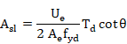
8) Obtaining the necessary torsion reinforcement. The necessary longitudinal reinforcement is calculated as a function of the transverse reinforcement, using the following expression:
![]()
Where:
![]() defined longitudinal reinforcement
defined longitudinal reinforcement
![]() necessary longitudinal reinforcement
necessary longitudinal reinforcement
![]() area of transverse reinforcement
area of transverse reinforcement
For each element end, calculated results are written in the CivilFEM results file in the following parameters:
ALT Area of necessary longitudinal torsion reinforcement in compliance with the defined transverse reinforcement.
![]()
CRTALT Ratio between the area of the required longitudinal torsion reinforcement and the area of the defined longitudinal torsion reinforcement.
![]()
9) Obtaining torsion criterion. The torsion criterion identifies the ratio of the design moment to the section’s ultimate strength (if it is less than 1, the section is valid; whereas if it exceeds 1, the section is not valid). The criterion concerning the validity for torsion is defined as follows:

For each element end, this value is stored in the CivilFEM results file as CRT_TOT.
A value 2100 for this criterion indicates that any one of the torsion reinforcements are not defined.
11-B.4.3 Combined Shear and Torsion Checking
Checking sections subjected to shear force and concomitant torsional moment follows the steps below:
1) Shear checking disregarding the torsional moment. This check follows the same procedure as the check of elements subjected to shear.
In this case, the total shear criterion CRT_TOT is named as CRTSHR.
2) Torsion checking disregarding the shear force. This check will be accomplished with the same procedure as the check of elements subjected to torsion, considering the torsional force due to shear in the calculation of concrete failure.
![]()
![]()
In this case, the total torsion criterion CRT_TOT is named as CRTTRS.
3) Obtaining the criterion of combined shear and torsion. This criterion contains both shear and torsion criteria:
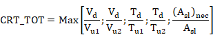
For each element end, calculated results are written in the CivilFEM results file in the parameter CRT_TOT.
11-B.4.4 Shear Design
The shear design according to BS8110 follows these steps:
1) Obtaining material strength properties. These properties are obtained from the material properties associated to each transverse cross section and for the active time (see command ~CFMP).
The required data are the following:
![]() characteristic compressive strength of concrete.
characteristic compressive strength of concrete.
![]() characteristic yield strength of reinforcement.
characteristic yield strength of reinforcement.
![]() concrete partial safety factor.
concrete partial safety factor.
2) Obtaining geometrical data of the section. Section geometrical requirements must be defined within CivilFEM database, (~CSECDMS commands). Required data for shear checking are the following:
![]() total area of the concrete transverse section.
total area of the concrete transverse section.
h total depth in the shear direction considered.
3) Obtaining geometrical parameters depending on specified code. Geometrical parameters used for shear calculations must be defined within CivilFEM database, (see ~SECMDF command). Required data are the following:
![]() minimum width of the
section, (parameter BW_VY or BW_VZ of ~SECMDF
command).
minimum width of the
section, (parameter BW_VY or BW_VZ of ~SECMDF
command).
d effective depth of the section, (parameter D_Y or D_Z of ~SECMDF command).
![]() Area of the longitudinal tension reinforcement that
extends at least a distance d beyond the considered section.
Area of the longitudinal tension reinforcement that
extends at least a distance d beyond the considered section.
Section 11-A.7 “Previous Considerations to Shear and Torsion Calculation” provides detailed information on how to calculate the required data for each code and valid section.
4) Obtaining reinforcement data of the section. Data concerning reinforcements of the section must be included within CivilFEM database, (see ~RNFDEF and ~RNFMDF commands). Required data are the following ones:
a angle between shear reinforcement and the longitudinal axis of the member. For this code, a = 90º.
5) Obtaining forces and moments acting on the section. The shear force that acts on the section as well as the concomitant axial force and bending moment are obtained from the CivilFEM results file (.RCV).
Force Description
![]() Design shear force
Design shear force
![]() Concomitant axial force
Concomitant axial force
M Concomitant bending moment
6) Checking the crushing of the web in compression. First, a check is made to ensure the design shear force (![]() ) is less than or equal to the oblique compression resistance of
concrete section (
) is less than or equal to the oblique compression resistance of
concrete section (![]() ):
):
![]()
![]()
For each element end, calculated results are written in the CivilFEM results file in the following parameters:
VU1 Ultimate shear strength due to oblique compression of the concrete in web.
![]()
CRTVU1 Ratio
of the design shear (![]() ) to the resistance
) to the resistance ![]() .
.
![]()
If the design shear force is greater than the shear force that causes failure in the web, the section will not be designed. Therefore, the parameter for the reinforcement data will be defined as 2100.
![]()
For this case, the element will be labeled as not designed.
7) Calculating the concrete shear resistance. The shear resistance of concrete (Vc) is checked using the following expression:
Where:
![]() Area of the longitudinal tension reinforcement that
extends at least a distance d beyond the considered section.
Area of the longitudinal tension reinforcement that
extends at least a distance d beyond the considered section.
Taking into account the following restrictions:
![]()
![]()
If ![]() the results are multiplied by
the results are multiplied by ![]()
If the section is subjected to an axial force, then the following expression will be used:
![]()
Where:
h total depth in the shear direction considered.
![]() concrete shear resistance without axial forces.
concrete shear resistance without axial forces.
Taking into
account that 
For each element end, calculated results are written in the CivilFEM results file in the following parameters:
VC concrete shear resistance:
![]()
8) Determining the contribution of the required transverse reinforcement to the shear force. If the section requires shear reinforcement, the condition for the validity of sections subjected to shear force is the following:
![]()
![]()
![]() is the reinforcement
contribution.
is the reinforcement
contribution.
![]() is the concrete
contribution.
is the concrete
contribution.
![]()
For each element end, calculated results are written in the CivilFEM results file in the following parameter:
VS Transverse reinforcement shear resistance.
![]()
9) Calculating the required reinforcement ratio. Once the shear force that must be carried by the shear reinforcement has been obtained, this can be calculated from the equation below:

where:
![]() area per unit length of
shear reinforcement.
area per unit length of
shear reinforcement.
![]() characteristic yield strength of shear reinforcement.
characteristic yield strength of shear reinforcement.
The area of designed reinforcement per unit length is stored in the CivilFEM results file for both ends:
![]()
In this case the element is marked as designed (provided that the design process is correct for both element sections).
11-B.4.5 Torsion Design
Torsion reinforcement design according to BS8110 follows the following steps:
1) Obtaining material strength properties. These properties are obtained from the material properties associated to each transverse cross section and for the active time, (see ~CFMP command).
The required data are the following ones:
![]() characteristic compressive strength of concrete.
characteristic compressive strength of concrete.
![]() characteristic yield strength of reinforcement.
characteristic yield strength of reinforcement.
2) Obtaining geometrical parameters depending on specified code. Geometrical parameters used for torsion calculations must be defined within CivilFEM database. The required data are the following ones:
![]() torsion modulus for torsion checking and dimensioning.
torsion modulus for torsion checking and dimensioning.
![]() minimum distance of the rectangular stirrups.
minimum distance of the rectangular stirrups.
![]() maximum distance of the rectangular stirrups.
maximum distance of the rectangular stirrups.
Section 11-A.7 “Previous Considerations to Shear and Torsion Calculation” provides detailed information on how to calculate the required data for each code and valid section.
3) Obtaining section internal forces and moments. The torsional moment that acts on the section is obtained from the CivilFEM results file (.RCV).
Moment Description
![]() Design torsional moment
Design torsional moment
4) Checking if torsion effects must be considered. Torsion effects are only considered if design torsional moment (![]() ) satisfies the condition below:
) satisfies the condition below:
![]()
with ![]()
![]()
Where:
![]() minimum torsional stress
minimum torsional stress
If the design torsional moment is less than this value, its effects can be neglected and its default value will be defined as 0 for checking purposes.
5) Checking concrete failure. The
design torsional moment Td must be less than or equal to the maximum
torsional moment that concrete can resist (![]() ); therefore:
); therefore:
![]()
![]()
If y1< 550mm![]()
Where:
![]() N/mm2 is the maximum allowable stress.
N/mm2 is the maximum allowable stress.
![]() torsion modulus for torsion check and design.
torsion modulus for torsion check and design.
For each element end, calculated results are written in the CivilFEM results file in the following parameters:
TU1 Maximum torsional moment that can be resisted by the section.
![]()
CRTTU1 Ratio of the design torsional moment (Td) to the resistance Tu1.
![]()
In case the torsion transverse reinforcement is not defined, the criterion is taken as 2100.
If the design torsional moment is greater than the torsional moment that causes the compression failure of concrete, the reinforcement design will not be feasible. Therefore, the parameters for reinforcement data will be assigned a value of 2100.
![]() for transverse reinforcement
for transverse reinforcement
![]() for longitudinal reinforcement
for longitudinal reinforcement
In this case, the element is marked as not designed, and the program then advances to the next element.
If there is no failure due to oblique compression, the calculation process continues.
6) Calculating the transverse reinforcement required. The design torsional reinforcement must be less than or equal to the resistance torsional reinforcement:
![]()
![]()
Where:
![]() area of transverse reinforcement per unit length
area of transverse reinforcement per unit length
![]() characteristic yield strength of reinforcement
characteristic yield strength of reinforcement ![]()
Therefore, the required transverse reinforcement is:

The area per unit length of the designed transverse reinforcement is stored in the CivilFEM results file for both element ends as:
![]()
7) Calculating the longitudinal reinforcement required. The longitudinal reinforcement is calculated as a function of the transverse reinforcement using the expression:
![]()
Where:
![]() required longitudinal reinforcement.
required longitudinal reinforcement.
![]() area per unit length of transverse reinforcement.
area per unit length of transverse reinforcement.
For each element end, calculated results are written in the CivilFEM results file in the following parameter:
ASLT Area of longitudinal torsion reinforcement.
![]()
11-B.4.6 Combined Shear and Torsion Design
The design of sections subjected to shear force and concomitant torsional moment follows the steps below:
1) Shear design assuming a null torsional moment. This design follows the same steps as for the design of elements subjected to pure shear according to BS8110.
2) Torsion design assuming a null shear force. This design is accomplished with the same procedure as for the designing of elements subjected to torsion force according to BS8110. However, this design considers the stress due to shear in the calculation of concrete failure.
![]()
![]()
Where:
![]() maximum combined shear stress (shear plus torsion).
maximum combined shear stress (shear plus torsion).
![]() torsion modulus for torsion check and design.
torsion modulus for torsion check and design.
11-B.5 Shear and Torsion according to AS3600
This standard works internally with Millimeters, Newtons and Megapascals. Therefore, if the user chooses another unit system, the necessary unit modifications will take place in order to use the AS600 formulation. Once the check or the design is carried out, the modification will be undone in order to obtain the results in user’s units. The value f will be equal to 0.7 for shear and torsion.
11-B.5.1 Shear Checking
1) Obtaining the material strength properties. They are obtained from the material associated to each cross-section and for the active time (see ~CFMP command).
The required data are:
![]() concrete strength.
concrete strength.
![]() yield strength of the reinforcing steel.
yield strength of the reinforcing steel.
2) Obtaining the geometric data of the section. The geometric data of the section will be included in the CivilFEM’s database, (see ~CSECDMS commands). The required data for the shear checking are:
![]() concrete section area.
concrete section area.
3) Obtaining the geometric parameters that depend on the standard. The geometric parameters used for the shear calculations dependent on the standard and will be defined in CivilFEM’s database, (~SECMDF command). The required data are:
![]() Web width or diameter
of the circular section, (BW_VY or BW_VZ parameter of the ~SECMDF command).
Web width or diameter
of the circular section, (BW_VY or BW_VZ parameter of the ~SECMDF command).
![]() distance from the
extreme compression fiber to the centroid of the longitudinal tension
reinforcement according to Y ( in circular sections, this distance should not
be less than the distance from the extreme compression fiber to the centroid of
the tension reinforcement in the opposite half of the piece, (parameter DO_Y or
DO_Z of the ~SECMDF command).
distance from the
extreme compression fiber to the centroid of the longitudinal tension
reinforcement according to Y ( in circular sections, this distance should not
be less than the distance from the extreme compression fiber to the centroid of
the tension reinforcement in the opposite half of the piece, (parameter DO_Y or
DO_Z of the ~SECMDF command).
Section 11-A.7 “Previous Considerations to Shear and Torsion Calculation” provides detailed information on how to calculate the required data for each code and valid section.
4) Obtaining the reinforcement data of the section. The section reinforcement data should be defined in the database of CivilFEM, (see ~RNFDEF and ~RNFMDF). The required data are:
a Angle formed by the reinforcement with the longitudinal axis of the piece where they meet (ALPHA parameter of the ~RNFDEF or ~RNFMDF command).
![]() Reinforcement area per length unit, (AS/S parameter of the
command ~RNFDEF or ~RNFMDF).
Reinforcement area per length unit, (AS/S parameter of the
command ~RNFDEF or ~RNFMDF).
Alternatively to the previous reinforcement piece of information, the amount of reinforcement can be indicated by means of:
![]() total area in the reinforcement legs (AS parameter of
the ~RNFDEF or ~RNFMDF
command).
total area in the reinforcement legs (AS parameter of
the ~RNFDEF or ~RNFMDF
command).
s spacing among stirrups, ( S parameter of the ~RNFDEF or ~RNFMDF command).
Or by means of the following data:
s spacing among stirrups ( S parameter of the ~RNFDEF or ~RNFMDF command).
f diameter of the bars, (PHI parameter of the ~RNFDEF or ~RNFMDF command).
N reinforcement leg number, (N parameter of the ~RNFDEF or ~RNFMDF parameter).
5) Obtaining of the forces and moments that act on the section. The shear force that acts on the section as well as the concomitant axial force is obtained from the result file of CivilFEM (.RCV).
Force Description
![]() Calculated shear force
Calculated shear force
![]() Calculated concomitant axial force
Calculated concomitant axial force
6) Checking the crushing due to compression in the web. Firstly, the program checks if the shear design (![]() ) is less than the web compression resistance:
) is less than the web compression resistance:
![]()
![]()
For each element end, calculated results are written in the CivilFEM results file in the following parameters:
VUMAX Shear failure due to crushing of the web.
![]()
CRTVUMAX Web crushing criterion
![]()
7) Calculating the shear resistance of concrete. The concrete shear resistance is calculated is follows:

where

![]() sections in tension
sections in tension
![]() sections in compression
sections in compression
![]()
![]() Area of the tensional bending reinforcement.
Area of the tensional bending reinforcement.
The calculated results are stored in the result file of CivilFEM in the following parameters:
VUC Shear strength provided by concrete in the section
![]()
BETA1 Partial
coefficient for the ![]() calculation.
calculation.
![]()
BETA2 Partial
coefficient for the ![]() calculation.
calculation.
![]()
8) Calculating the shear strength of the reinforcement. The strength provided by the reinforcement (![]() ) is evaluated by the expression:
) is evaluated by the expression:
![]()
Where:
![]() Shear transverse
reinforcement area.
Shear transverse
reinforcement area.
![]() Yield strength of the reinforcement.
Yield strength of the reinforcement.
s Distance between the shear stirrups.
The calculated result is stored in the result file of CivilFEM in the following parameter:
VUS Shear strength provided by the transverse reinforcement
![]()
9) Nominal shear strength of the section. The nominal shear strength (![]() ) is the sum of the nominal strength provided by the concrete and
the strength provided by the shear reinforcement:
) is the sum of the nominal strength provided by the concrete and
the strength provided by the shear reinforcement:
![]()
This nominal strength and the relation with the calculated shear force are stored in the result file of CivilFEM as well as the following parameter:
VU Nominal shear strength of the section.
![]()
10) Obtaining the shear criterion. The shear force V* must be lower than fVu, being ![]()
![]()
f the reduction factor of the section strength, (equal to 0.7 for shear).
Therefore, the possible criteria to determine the validity of the section are:
CRTVU Relation
between the calculated shear (![]() ) and the strength
) and the strength ![]()
![]()
In the case
that the shear strength of the concrete equals zero and the shear reinforcement
is not defined in the section ![]() , the value 2100 will be assigned to the criterion.
, the value 2100 will be assigned to the criterion.
CRTVUMAX Relation
between the calculated shear (![]() ) and the strength
) and the strength ![]()
![]()
CRT_TOT is the maximum of CRTVU, CRTVUMAX.
![]()
This value is stored for each end in the result file of CivilFEM in the parameter CRT_TOT.
If the strength
provided by the concrete equals zero and the shear reinforcement is not defined
in the ![]() section, the value 2100 will be assigned to the
criterion.
section, the value 2100 will be assigned to the
criterion.
11-B.5.2 Torsion Checking
The torsion element check according to AS36000 is composed by the following steps:
1) Obtaining of the strength properties of the materials. They are obtained from the material associated to each cross-section and for the active time, (see ~CFMP command).
The required data are the following:
![]() concrete strength.
concrete strength.
![]() yield strength of the reinforcing steel.
yield strength of the reinforcing steel.
2) Obtaining the geometric parameters that depend on the standard. The geometric parameters used in the torsion calculations depending on the standard should be defined in the CivilFEM’s database, (see ~SECMDF command). The necessary data are:
![]() Web width or circular
section diameter ( BW_VY or BW_VZ parameter of the command ~SECMDF).
Web width or circular
section diameter ( BW_VY or BW_VZ parameter of the command ~SECMDF).
![]() The distance from the extreme compression fiber to the
centroid of the longitudinal tension reinforcement according to Y (in circular
sections this must be less than the distance from the extreme compression fiber
to the centroid of the tensile reinforcement in the opposite half of the member,
(DO_Y or DO_Z parameters of the ~SECMDF command).
The distance from the extreme compression fiber to the
centroid of the longitudinal tension reinforcement according to Y (in circular
sections this must be less than the distance from the extreme compression fiber
to the centroid of the tensile reinforcement in the opposite half of the member,
(DO_Y or DO_Z parameters of the ~SECMDF command).
Section 11-A.7 “Previous Considerations to Shear and Torsion Calculation” provides detailed information on how to calculate the required data for each code and valid section.
3) Obtaining the reinforcement data of the section. The section reinforcement data must be defined in the database of CivilFEM, (see ~RNFDEF and ~RNFMDF commands). The necessary data are:
Transverse Reinforcement
Ast/s transverse reinforcement area per unit length (AST/S parameter of the ~RNFDEF or ~RNFMDF command).
Alternatively, the reinforcement can also be calculated with:
![]() critical tensile zone, ( AST parameter of the ~RNFDEF or ~RNFMDF command).
critical tensile zone, ( AST parameter of the ~RNFDEF or ~RNFMDF command).
s spacing between stirrups, (ST parameter of the ~RNFDEF or ~RNFMDF command).
Or introducing the following data:
s spacing between stirrups (ST parameter of the ~RNFDEF or ~RNFMDF command).
![]() diameter of the bar of the stirrup, (PHIT parameter of
the ~RNFDEF or ~RNFMDF
command).
diameter of the bar of the stirrup, (PHIT parameter of
the ~RNFDEF or ~RNFMDF
command).
Longitudinal Reinforcement
![]() Total area of the longitudinal reinforcement, (ASL
parameter of the ~RNFDEF or ~RNFMDF command).
Total area of the longitudinal reinforcement, (ASL
parameter of the ~RNFDEF or ~RNFMDF command).
Alternatively, the reinforcement can be calculated from:
![]() Longitudinal bar diameter, (PHIL diameter of the ~RNFDEF or ~RNFMDF command).
Longitudinal bar diameter, (PHIL diameter of the ~RNFDEF or ~RNFMDF command).
N Longitudinal bar number, (N parameter of the ~RNFDEF or ~RNFMDF command).
4) Obtaining the force and moments that act on the section. The torsional moment that acts over the section is obtained from the result file of CivilFEM.
Force Description
![]() Torsional moment
Torsional moment
5) Checking the torsional effects limitation. The torsional effects are limited by the web crushing:
![]()
Where f is the strength reduction factor.
6) Checking the necessary torsional reinforcement. In the following cases, reinforcement is not considered necessary:
i) ![]()
ii) ![]()
iii) The total depth does not exceed the maximum of {250 mm; 0.5* web width} and also:
![]()
Where
f Strength reduction factor.
![]()
If the i), ii) or iii) conditions are not satisfied, the section should be reinforced in the transverse as well as the longitudinal direction.
7) Calculating the transversal reinforcement required. It must satisfy the following condition:
![]()
Where,

![]() Defined by the user between 30º and 45º
Defined by the user between 30º and 45º
![]() Yield strength of the reinforcement
Yield strength of the reinforcement
![]() Torsional stirrup area
Torsional stirrup area
![]() Polygonal area of the
reinforcement
Polygonal area of the
reinforcement
s Distance between shear stirrup
8) Caculating the longitudinal reinforcement required. The following condition must be satisfied:
![]()
Where
![]() Longitudinal
reinforcement area
Longitudinal
reinforcement area
![]() Torsional stirrup area
Torsional stirrup area
![]() Perimeter of
Perimeter of ![]()
s Distance between torsional stirrups
9) Obtaining the torsional criterion. The calculated results are stored in the result file of CivilFEM in the following parameters:
TUMAX Ultimate torsional moment of the concrete web failure.
![]()
CRTTUMAX Relation
between the torsional moment (![]() ) and the strength
) and the strength ![]()
![]()
TUC Torsional strength without torsional reinforcement
![]()
TUS Torsional strength with torsional reinforcement
![]()
CRTTUC Relation
between the torsional moment (![]() ) and the strength
) and the strength ![]()
![]() for only torsional moment
for only torsional moment
CRTTUS Relation
between the torsional moment (![]() ) and the strength
) and the strength ![]()
![]() for only torsional moment
for only torsional moment
ATL Longitudinal reinforcement area
![]()
CRTATL Relation between the longitudinal reinforcement area calculated and the section area.
![]()
CRT_TOT Total Criterion. The following criteria are checked in this order:
- If CRTTUC £ 0.5: CRT_TOT= max{ CRTWCRUS, CRTTUC}
- If CRTTUC £ 1 and the total depth does not exceed the maximum of {250 mm; 0.5*web width}: CRT_TOT= max {CRTWCRUS, CRTTUC}
- Finally, CRT_TOT= max {CRTWCRUS, CRTTUS, CRTATL}
This value is stored for each element end in the result file of CivilFEM in the parameter CRT_TOT.
If the strength provided by concrete equals zero and the torsional reinforcement is not defined in the section, the value 2100 will be assigned to the criterion.
11-B.5.3 Checking of Combined Shear and Torsion
In order to check the section for a shear force and a concomitant torsional moment, the following process is followed:
1) Checking crushing due to compression in the web. The combined shear and torsional effects are limited by the crushing of the web:
![]()
2) Shear checking with a concomitant torsional moment. This check follows the same steps as the check for elements only subjected to shear according to AS3600.
Calculated results are equivalent to those of the section corresponding to shear checking.
3) Checking combined torsion and shear. This checking is accomplished with the same steps as the check of elements subjected to pure torsional moment according to AS3600.
Calculated results are equivalent to those of the section corresponding to torsional checking.
4) Obtaining the combined shear and torsional criterion. The calculated results are stored in a result file of CivilFEM in the following parameters:
CRTWCRUS Web crushing criterion
![]()
CRTTUC Relation
between the torsional moment (![]() ) and the strength
) and the strength ![]()
![]()
CRTTUS Relation
between the torsional moment (![]() ) and the strength
) and the strength ![]()
![]()
The total criterion will be calculated using the following procedure:
CRT_TOT Total Criterion. The following criteria are checked in this order:
- If CRTTUC £ 0.5: CRT_TOT= max {CRTWCRUS, CRTTUC}
- If CRTTUC £ 1 and the total depth does not exceed the maximum of {250 mm; 0.5*width web}:CRT_TOT= max {CRTWCRUS, CRTTUC}
- Finally, CRT_TOT= max {CRTWCRUS, CRTTUS, CRTATL}
The value of this criterion is stored for each extreme in the result file of CivilFEM in the parameter CRT_TOT.
A 2100 value for this criterion indicates:
· the concrete shear strength is null and the shear reinforcement is not defined.
· the concrete torsional strength is null and the transversal torsional reinforcement is not defined.
· the longitudinal torsional reinforcement has not been defined
11-B.5.4 Shear Design
The shear reinforcement design according to AS3600 is composed of the following steps:
1) Obtaining of the strength properties of the materials. A material associated to each cross-section is obtained and for the active time (see ~CFMP command).
The necessary data are:
![]() concrete strength.
concrete strength.
![]() Yield strength of the reinforcing steel.
Yield strength of the reinforcing steel.
2) Obtaining the geometric data of the section. The geometric data of the section must be stored in the database of CivilFEM, (see ~CSECDMS commands). The necessary data for shear checking are:
![]() concrete section area.
concrete section area.
3) Obtaining the geometric parameters that depend on the standard. The code dependent geometric parameters used for the shear calculations should be defined in the CivilFEM database (~SECMDF command).
The necessary data are:
![]() web width or circular
section diameter (BW_VY or BW_VZ parameters of the ~SECMDF
command).
web width or circular
section diameter (BW_VY or BW_VZ parameters of the ~SECMDF
command).
![]() distance from the
extreme compression fiber to the centroid of the longitudinal tensile reinforcement
according to Y (in circular sections, this should not be less than the distance
from the extreme compression fiber to centroid of the tensile reinforcement in
the opposite half of the member (DO_Y or DO_Z parameter of the ~SECMDF command.)
distance from the
extreme compression fiber to the centroid of the longitudinal tensile reinforcement
according to Y (in circular sections, this should not be less than the distance
from the extreme compression fiber to centroid of the tensile reinforcement in
the opposite half of the member (DO_Y or DO_Z parameter of the ~SECMDF command.)
Section 11-A.7 “Previous Considerations to Shear and Torsion Calculation” provides detailed information on how to calculate the required data for each code and valid section.
4) Obtaining the reinforcement data of the section. In shear reinforcement design, it is possible to define the a angle between the reinforcement and the longitudinal axis of the member. This angle should be stored in the reinforcement data correspondent to each element, ALPHA parameter of the ~RNFDEF or ~RNFMDF commands. If it equals zero or is not defined, a=90º. The remaining data pertaining to the reinforcements are ignored.
5) Obtaining the forces that act in the section. The shear force as well as the concomitant axial force are obtained from the CivilFEM results file.
Force Description
![]() Calculated shear
Calculated shear
![]() Concomitant axial force
Concomitant axial force
6) Checking crushing of the web. Firstly,
a check is made to ensure the design shear (![]() ) is less than or equal to the web compression resistance:
) is less than or equal to the web compression resistance:
![]()
![]()
For each element end, calculated results are written in the CivilFEM results file in the following parameters:
VUMAX Shear failure due to crushing of the web.
![]()
CRTVUMAX Web crushing criterion:
![]()
7) Calculating the concrete shear resistance. The concrete shear resistance is calculated as follows:

Where:
![]() sections in tension
sections in tension
![]() sections in compression
sections in compression
![]()
![]() Area of the tensional bending reinforcement.
Area of the tensional bending reinforcement.
The calculated results are stored in the result file of CivilFEM in the following parameters:
VUC Shear strength provided by concrete in the section
![]()
BETA1 Partial coefficient for the VUC calculation.
![]()
BETA2 Partial coefficient for the VUC calculation.
![]()
8) Calculating the necessary reinforcement amount. The shear strength supported by the reinforcement is![]() . If
. If ![]() produces a negative value, reinforcement will not be necessary.
produces a negative value, reinforcement will not be necessary.
The reinforcement amount is:

where,
![]() shear transverse reinforcement area.
shear transverse reinforcement area.
s spacing of stirrups measured according to longitudinal axis.
![]() yield strength of the shear reinforcement.
yield strength of the shear reinforcement.
![]() angle between stirrups and the longitudinal axis, ALPHA
parameter of the ~RNFDEF or ~RNFMDF commands.
angle between stirrups and the longitudinal axis, ALPHA
parameter of the ~RNFDEF or ~RNFMDF commands.
![]() angle of the shear compression struts.
angle of the shear compression struts.
![]() ultimate strength due to the shear reinforcement only.
ultimate strength due to the shear reinforcement only.
The calculated results are stored in the result file of CivilFEM for the following parameters:
ASSH Area per unit length of the designed reinforcement
![]()
VUS Ultimate strength due to the shear reinforcement.
![]()
DSG_CRT Design criterion (OK, the element has been designed and Not OK, the element has not been designed).
DSG_CRT=DSG_CRT
11-B.5.5 Torsion Design
The torsion reinforcement design according to the AS600 is composed by the following steps:
1) Obtaining material strength properties. These properties are obtained from the material associated with each cross-section and for the active time (see ~CFMP command).
The required data are:
![]() concrete strength
concrete strength
![]() yield strength of the reinforcing steel.
yield strength of the reinforcing steel.
2) Obtaining of the geometric parameters that depend on the standard. The standard dependent geometric parameters used for the torsional calculations should be defined in the database of CivilFEM (~SECMDF command). The required data are:
![]() Web width or circular
section diameter (BW_VY or BW_VZ parameters of the ~SECMDF
command).
Web width or circular
section diameter (BW_VY or BW_VZ parameters of the ~SECMDF
command).
![]() distance from the extreme compression fiber to the centroid
of the longitudinal tensile reinforcement according to Y ( in circular sections,
this should not be less than the distance from the extreme compression fiber to
the centroid of the tensile reinforcement in the opposite half of the member,(
DO_Y or DO_Z parameter of the ~SECMDF command).
distance from the extreme compression fiber to the centroid
of the longitudinal tensile reinforcement according to Y ( in circular sections,
this should not be less than the distance from the extreme compression fiber to
the centroid of the tensile reinforcement in the opposite half of the member,(
DO_Y or DO_Z parameter of the ~SECMDF command).
![]() Torsional stirrup area, (Asw parameter of the ~SECMDF command).
Torsional stirrup area, (Asw parameter of the ~SECMDF command).
![]() Longitudinal reinforcement area, (Atl
parameter of the ~SECMDF command).
Longitudinal reinforcement area, (Atl
parameter of the ~SECMDF command).
Section 11-A.7 “Previous Considerations to Shear and Torsion Calculation” provides detailed information on how to calculate the required data for each code and valid section.
3) Obtaining the forces that act on the section. The torsional moment that acts on the section is obtained in the result file of CivilFEM (.RCV).
Force Description
![]() Calculated torsional moment
Calculated torsional moment
4) Checking the torsional effects limitation. The torsional effects are limited by the crushing of the web:
![]()
Where f is the strength reduction factor.
5) Checking if the torsional reinforcement will be required. Reinforcement will not be necessary for the following cases:
i) ![]()
ii) ![]()
iii) The total depth does not exceed the maximum of {250 mm; 0.5*web width} and also:
![]()
where
f Strength reduction factor.
![]()
![]() Torsional modulus
Torsional modulus
If the i), ii) and iii) conditions are not satisfied, the member should be reinforced in the transverse and longitudinal directions.
6) Determining the transverse reinforcement requirement. The transverse reinforcement area per unit length is calculated by means of the following formula:

![]()
where,
![]() The area of the polygon that contains the
reinforcement.
The area of the polygon that contains the
reinforcement.
![]() The angle of the torsional compression struts.
The angle of the torsional compression struts.
The area per unit length of the transverse designed reinforcement is stored in the result file of CivilFEM in the parameter:
![]()
7) Determining the longitudinal reinforcement requirement. The longitudinal reinforcement area is the result of the following expression:
![]()
where,
![]() Torsional stirrup area
Torsional stirrup area
![]() Perimeter of
Perimeter of ![]()
![]() Angle of the torsional compression struts.
Angle of the torsional compression struts.
s Spacing between torsional stirrups
The area of the designed longitudinal reinforcement is stored in the result file of CivilFEM in the parameter:
![]()
If the design of the transverse reinforcement as well as the longitudinal reinforcement is carried out, for both element sections, this will be considered to be the design.
DSG_CRT Design Criterion (OK, the element has been designed and Not OK, the element has not been designed.)
11-B.5.6 Combined Shear and Torsion Design
In order to execute the design of the shear force sections and the concomitant torsional moment, the following process is followed:
1) Obtaining of the acting forces on the section. The torsional moment that acts on the section is obtained from the result file of CivilFEM (.RCV).
Force Description
![]() Calculated torsional moment
Calculated torsional moment
![]() Calculated shear force
Calculated shear force
2) Checking torsional effects limitation.
The torsional effects are only taken into consideration if the following
condition is satisfied for the calculation of the torsional moment (![]() ):
):
![]()
If the calculated torsional moment is less than this value, then its effects are not considered and the design equals zero.
3) Calculating the torsional reinforcement requirement. A reinforcement is not necessary in the following cases:
i)
![]()
ii) ![]()
iii) The total depth does not exceed the maximum of {250 mm ; 0.5*web width} and also:
![]()
where
f Strength reduction factor.
![]()
![]() Torsional modulus
Torsional modulus
![]() Ultimate strength without reinforcement.
Ultimate strength without reinforcement.
If the i), ii), or iii) conditions are not fulfilled, it should be transversally and longitudinally reinforced. If the relation in the previous step is not satisfied, the torsional reinforcement cannot be designed and therefore, the parameters where the reinforcement data are stored will be labeled with 2100.
![]() for the transverse reinforcement
for the transverse reinforcement
![]() for the longitudinal reinforcement
for the longitudinal reinforcement
4) Calculating the transversal reinforcement required. The transversal reinforcement area per unit length is determined by:

![]()
where,
![]() Polygonal area
of the reinforcement
Polygonal area
of the reinforcement
![]() Angle of the torsional compression struts
Angle of the torsional compression struts
The designed transversal reinforcement area is stored in the result file of CivilFEM in the parameter:
![]()
5) Calculating the longitudinal reinforcement requirement. The longitudinal reinforcement area is calculated by the following equation:
![]()
Where:
![]() Area of torsional stirrups
Area of torsional stirrups
![]() Perimeter of At
Perimeter of At
![]() Angle of compression struts in torsion
Angle of compression struts in torsion
s Distance between torsion stirrups
The area of longitudinal reinforcement is stored in the results file of CivilFEM in the parameter:
![]()
If the transverse reinforcement as well as the longitudinal reinforcement is defined, the section will be labeled as designed.
DSG_CRT Design Criterion (Ok, the element has been designed and Not Ok, the element has not been designed.)
11-B.6 Shear and Torsion according to GB50010-2002
11-B.6.1 Shear Checking
Shear checking for elements according to GB50010-2002 follows the steps below:
1) Obtaining materials strength properties. These properties are obtained from the material properties associated with each transverse cross section and for the active time, (see ~CFMP command). Those material properties should be defined previously. The required data are the following:
![]() design compressive strength of concrete.
design compressive strength of concrete.
![]() design tensile
strength of concrete.
design tensile
strength of concrete.
![]() steel design tensile strength for of shear
reinforcement.
steel design tensile strength for of shear
reinforcement.
2) Obtaining geometrical data of the section. Section geometrical requirements must be defined within the CivilFEM database, (~CSECDMS commands). Required data for shear checking are the following:
![]() total cross-sectional area of the concrete section.
total cross-sectional area of the concrete section.
3) Obtaining geometrical parameters depending on specified code. Geometrical parameters used for shear calculations must be defined within the CivilFEM database, see ~SECMDF command. Required data are the following:
b minimum width of the section over the effective depth, (parameter BW_VY or BW_VZ of ~SECMDF command)
![]() effective height of
the section, (parameter D_Y or D_Z of ~SECMDF
command).
effective height of
the section, (parameter D_Y or D_Z of ~SECMDF
command).
![]() the web height (parameter HW_VY of ~SECMDF command).
the web height (parameter HW_VY of ~SECMDF command).
4) Obtaining the reinforcement data of the section. The section reinforcement data should be defined in the database of CivilFEM, (see ~RNFDEF and ~RNFMDF). The necessary data are:
a Angle formed by the reinforcement with the longitudinal axis of the piece where they meet (ALPHA parameter of the ~RNFDEF or ~RNFMDF command).
![]() Reinforcement area per length unit, (AS/S parameter of the
command ~RNFDEF or ~RNFMDF).
Reinforcement area per length unit, (AS/S parameter of the
command ~RNFDEF or ~RNFMDF).
Alternatively, the amount of reinforcement can be determined from:
![]() total area in the reinforcement legs (AS parameter of
the ~RNFDEF or ~RNFMDF
command).
total area in the reinforcement legs (AS parameter of
the ~RNFDEF or ~RNFMDF
command).
s spacing among stirrups, ( S parameter of the ~RNFDEF or ~RNFMDF command).
Or from the data below:
s spacing among stirrups ( S parameter of the ~RNFDEF or ~RNFMDF command).
f diameter among bars, (PHI parameter of the ~RNFDEF or ~RNFMDF command).
N reinforcement leg number, (N parameter of the ~RNFDEF or ~RNFMDF parameter).
5) Obtaining the section internal forces and moments. The shear force that acts on the section as well as the concomitant axial force and bending moment are obtained from the CivilFEM results file (.RCV).
Force Description
V Design shear force
N Axial force
11-B.6.2 Shear Checking without Seismic Action
1) Checking whether the section dimensions meet the requirement. First, a check is made to ensure the design shear (V) is less than
or equal to maximum shear resistance of the section (![]() ):
):
![]()
If ![]()
If ![]()
where bc is a coefficient depending on the concrete strength:
·
For concrete C50 (fc= 23.1 N/mm2) or
under, ![]() ;
;
·
For concrete C80 (fc= 35.9 N/mm2), ![]()
·
For concrete C55-75, a linear interpolation is
made for ![]() according to the values of fc.
according to the values of fc.
Results are written for each end in the CivilFEM results file as the following parameters:
VRD1 Maximum shear resistance.
![]()
CRVRD1 Ratio
of the design shear force V to the resistance ![]() .
.
![]()
2) Checking if shear reinforcement will be required.
If shear
reinforcement has not been defined for the section, a check is made to ensure
the design shear force V is less than the maximum design shear force that can
be resisted by the concrete without reinforcements (![]() ):
):
![]()
Where
![]()
![]() is the section
height factor,
is the section
height factor,
![]()
![]()
If reinforcement has been defined, axial forces are not present (N=0), and the shear force from the concentrated load for an independent beam is less than 75%:
![]()
If N is compressive (N < 0)
![]()
If N is tensile (N > 0)
![]()
The following are given in CivilFEM results:
VRD2 Maximum design shear force resisted by the section without the crushing of the concrete compressive struts.
![]()
CRVRD2 Ratio of
the design shear force V to the resistance ![]() .
.
![]()
For sections
subjected to an applied tensile axial force so that ![]() , CRVRD2 is taken as 2100.
, CRVRD2 is taken as 2100.
3) Checking of elements requiring shear reinforcement. The shear resistance calculation of a section with reinforcement (VRd3) will differ according to whether the concentrated load exists.
Conditions below must be verified:
![]()
where
![]()
![]() design shear load capacity of reinforcement.
design shear load capacity of reinforcement.
![]()
![]() However, if the shear force from the concentrated load is
more than 75% in an independent beam or an axial force exits,
However, if the shear force from the concentrated load is
more than 75% in an independent beam or an axial force exits, ![]()
![]() cross-sectional area of the shear reinforcement.
cross-sectional area of the shear reinforcement.
s spacing of the stirrups measured along the longitudinal axis.
![]() design
tensile strength of shear reinforcement.
design
tensile strength of shear reinforcement.
Results obtained are written for each end in the CivilFEM results file as the following parameters:
![]() Shear
strength of the reinforcement.
Shear
strength of the reinforcement.
VRD3 Design shear resistance.
![]()
CRVRD3 Ratio of
the design shear force V to the shear resistance ![]() .
.
![]()
If ![]() , CRVRD3 is taken as 2100.
, CRVRD3 is taken as 2100.
4) Obtaining the shear criterion. The shear criterion indicates the validity of the section (if less than 1, the section will be valid; if greater than 1 the section, is not good). Moreover, it provides information with regards to how much more load the section can resist. The shear criterion is defined as follows:
![]()
For each element end, calculated results are written in the CivilFEM results file in the parameter CRT_TOT.
A value of 2100
in this criterion will indicate that shear resistance (![]() ) is not been considered, as indicated in the previous step.
) is not been considered, as indicated in the previous step.
11-B.6.3 Shear Checking with Seismic Action
Shear checking of elements according to GB50010-2002 and GB50011-2001 follows the steps below:
1) Determining the factor for seismic fortification, used to adjust the shear capacity and performing the check for shear. Firstly, this checking method differs from the other typical checking methods:
![]()
V Design shear force
VR/ γRE Design shear resistance
γRE factor for seismic fortification, used to adjust the shear capacity. If the combination of the cases does not include the horizontal seismic action, γRE=1.
Otherwise, it is selected as illustrated in the following table.
|
Member |
Status |
γRE |
|
Beam |
Bending |
0.75 |
|
Column |
Eccentric
compression and |
0.75 |
|
|
Eccentric
compression and |
0.8 |
|
Shear wall |
Eccentric compression |
0.85 |
|
Other |
Shear Eccentric tension |
0.85 |
2) Checking whether section dimensions meet requirements under the
actions of seismic loads. First, a check is made to
ensure the design shear (V) is less than or equal to sectional maximum possible
resistance (![]() ) under the seismic loads:
) under the seismic loads:
![]()
For beam:
![]()
For column:

![]()
VRD1 Maximum possible shear resistance.
![]()
CRVRD1 Ratio
of the design shear force V to the resistance ![]() .
.
![]()
3) Checking whether shear reinforcement will be required for the section under actions of seismic loads.
If the member is a beam, axial forces are not present (N=0), and the shear force from the concentrated load is less than 75%:
![]()
If the member is an independent beam and the shear force from concentrated load is more than 75%:
![]()
If the member is a column and N is compressive (N < 0)
![]()
If N is tensile (N > 0)

The following are given in CivilFEM results:
VRD2 Maximum design shear force resisted by the section without crushing of the concrete compressive struts.
![]()
CRVRD2 Ratio of the design shear force V to the resistance VRd2.
![]()
For sections
subjected to an applied tensile axial force so that ![]() , CRVRD2 is taken as 2100.
, CRVRD2 is taken as 2100.
4) Checking of elements that will require shear reinforcement under the
actions of seismic loads. The calculated of the
shear resistance of a section with reinforcement (![]() ) differs according to whether the concentrated load exists.
) differs according to whether the concentrated load exists.
The following condition is checked:
![]()
where
![]()
![]() is the design shear load capacity of
reinforcement.
is the design shear load capacity of
reinforcement.
![]()
![]() for a beam, in which the shear force from the concentrated
load is less than 75% and axial forces are not present (N=0).
for a beam, in which the shear force from the concentrated
load is less than 75% and axial forces are not present (N=0).
![]() for an independent beam, in which the shear force from the
concentrated load is more than 75%, for a column or for the case in which an
axial force exists.
for an independent beam, in which the shear force from the
concentrated load is more than 75%, for a column or for the case in which an
axial force exists.
![]() is the cross-sectional area of the shear
reinforcement.
is the cross-sectional area of the shear
reinforcement.
s is the spacing of the stirrups measured along the longitudinal axis.
![]() is the
design tensile strength of shear reinforcement.
is the
design tensile strength of shear reinforcement.
Results obtained are written for each end in the CivilFEM results file as the following parameters:
![]() Shear
strength of the reinforcement.
Shear
strength of the reinforcement.
VRD3 Design shear resistance.
![]()
CRVRD3 Ratio
of the design shear force V to the shear resistance ![]() .
.
![]()
If ![]() , CRVRD3 is taken as 2100.
, CRVRD3 is taken as 2100.
5) Obtaining the shear criterion. The shear criterion indicates the validity of the section (if less than 1, the section conforms to code specifications; if greater than 1, the section is not valid). Moreover, it provides information with regards to how much more load section can resist. The shear criterion is defined as follows:
![]()
For each element end, calculated results are written in the CivilFEM results file in the parameter CRT_TOT.
A value of 2100
for this criterion indicates that shear resistance (![]() ) is not considered, as indicated in the previous step.
) is not considered, as indicated in the previous step.
11-B.6.4 Torsion Checking
The torsion checking according to GB50010-2002 follows the steps below:
1) Obtaining material strength properties. These properties are obtained from the material properties associated to the transverse cross section and for the active time, (see ~CFMP command).
The required data are the following:
![]() design compressive strength of concrete.
design compressive strength of concrete.
![]() design tensile strength of concrete.
design tensile strength of concrete.
![]() design tensile strength for torsion reinforcement.
design tensile strength for torsion reinforcement.
2) Obtaining section geometrical data. Section geometrical requirements must be defined within the CivilFEM database, (~CSECDMS commands). Required data for shear checking are the following ones:
![]() total cross-sectional area of the concrete section.
total cross-sectional area of the concrete section.
![]() thickness of a box
section (TWY)
thickness of a box
section (TWY)
3) Obtaining geometrical parameters depending on specified code. Geometrical parameters used for torsion calculations must be defined within the CivilFEM database, (see ~SECMDF command). The required data are the following:
b minimum width of the section over the effective depth, (parameter BW_VY or BW_VZ of ~SECMDF command), or section inner diameter for circular section.
![]() height of the
section, (parameter D_Y or D_Z of ~SECMDF
command)., section outer diameter for circular section.
height of the
section, (parameter D_Y or D_Z of ~SECMDF
command)., section outer diameter for circular section.
![]() the web height (parameter HW_VY of ~SECMDF command).
the web height (parameter HW_VY of ~SECMDF command).
![]() Plastic resistance of
torsion moment
Plastic resistance of
torsion moment
![]() Core area
Core area
![]() Core perimeter
Core perimeter
![]() Plastic resistance of
torsion moment for branch 1 for T and double T section/I-section.
Plastic resistance of
torsion moment for branch 1 for T and double T section/I-section.
![]() Core area for branch 1 for
T and double T section/I-section.
Core area for branch 1 for
T and double T section/I-section.
![]() Core perimeter for branch 1
for T and double T section/I-section.
Core perimeter for branch 1
for T and double T section/I-section.
![]() Plastic resistance of
torsion moment for branch 2 for T and double T section/I-section.
Plastic resistance of
torsion moment for branch 2 for T and double T section/I-section.
![]() Core area for branch 2 for
T and double T section/I-section.
Core area for branch 2 for
T and double T section/I-section.
![]() Core perimeter for branch 2
for T and double T section/I-section.
Core perimeter for branch 2
for T and double T section/I-section.
Section 11-A.7 “Previous Considerations to Shear and Torsion Calculation” provides detailed information on how to calculate the required data for each code and valid section.
4) Obtaining the reinforcement data section. The section reinforcement data must be defined in the database of CivilFEM, (see ~RNFDEF and ~RNFMDF commands). The required data are:
Transverse Reinforcement
![]() transverse reinforcement area per length unit (AST/S
parameter of the ~RNFDEF or ~RNFMDF command).
transverse reinforcement area per length unit (AST/S
parameter of the ~RNFDEF or ~RNFMDF command).
Alternatively, the amount of the reinforcement can be calculated from:
![]() critical tensile zone, (AST parameter of the ~RNFDEF or ~RNFMDF command).
critical tensile zone, (AST parameter of the ~RNFDEF or ~RNFMDF command).
s spacing between stirrups, (ST parameter of the ~RNFDEF or ~RNFMDF command).
Or from the data below:
s spacing between stirrups (ST parameter of the ~RNFDEF or ~RNFMDF command).
![]() diameter of the bar of the stirrup, (PHIT parameter of
the ~RNFDEF or ~RNFMDF
commands).
diameter of the bar of the stirrup, (PHIT parameter of
the ~RNFDEF or ~RNFMDF
commands).
Longitudinal Reinforcement
![]() Total area of the longitudinal reinforcement, (ASL
parameter of the ~RNFDEF or ~RNFMDF command).
Total area of the longitudinal reinforcement, (ASL
parameter of the ~RNFDEF or ~RNFMDF command).
Alternatively, the amount of the reinforcement can determined from:
![]() Longitudinal bar diameter, (PHIL diameter of the ~RNFDEF or ~RNFMDF command).
Longitudinal bar diameter, (PHIL diameter of the ~RNFDEF or ~RNFMDF command).
N Longitudinal bar number, (N parameter of the ~RNFDEF or ~RNFMDF command).
5) Obtaining section internal forces and moments. The torsional moment that acts on the section is obtained from the CivilFEM results file (.RCV).
Moment Description
T Design torsion moment
N Axial force
6) Checking if the section dimensions meet the requirement.
![]()
if![]() then
then ![]()
if![]() then
then ![]()
Results are written in the CivilFEM results file for both element ends as the parameters:
TRD1 Maximum possible resistance of torsional moment
![]()
CRTRD1 Ratio of
the design torsional moment T to the resistance ![]() .
.
![]()
7) Calculating the maximum torsional moment resisted without reinforcements.
![]()
where
For rectangular and circular sections:
![]()
N (< 0) is the compressive axial force,
if![]() , assume
, assume![]() .
.
For box sections (axial forces cannot be resisted):
![]()
![]() is the influence coefficient of the wall thickness of the box
section.
is the influence coefficient of the wall thickness of the box
section.
![]() , if
, if ![]() , assume,
, assume, ![]()
For T and double T sections/I-sections, these are divided into rectangle sections and therefore, follow the procedure according to rectangular sections.
Results are written in the CivilFEM results file for both element ends as the parameters:
TRD2 Maximum design torsional moment resisted by the section without crushing the concrete compressive struts.
![]()
CRTRD2 Ratio of the design torsional moment T to the resistance TRd2.
![]()
8)
Calculating the maximum torsional moment
resisted by the reinforcement. The design torsional
moment T must be less than or equal to the maximum design torsional moment
resisted by concrete and the reinforcement (![]() ); as a result, the following condition must be satisfied:
); as a result, the following condition must be satisfied:
![]()
where
![]()
![]() the ratio
between longitudinal reinforcement and hoop
the ratio
between longitudinal reinforcement and hoop
reinforcement strength ![]()
if![]() , assume
, assume ![]()
Calculated results are written in the CivilFEM results file for both element ends as the parameters:
![]() Torsion
strength of the reinforcement.
Torsion
strength of the reinforcement.
TRD3 Maximum design torsional moment resisted by concrete and the torsion reinforcement.
![]()
CRTRD3 Ratio of
the design torsional moment T to the resistance ![]() .
.
![]()
If transverse reinforcement is not defined, ![]() .
.
9) Obtaining criterion of torsion checking.
CRT_TOT = MAX (CRTRD1, CRTRD3)
11-B.6.5 Combined Shear and Torsion Checking
1) Checking for whether section dimensions meet the requirements.
![]()
![]()
Where
If ![]() or
or ![]()
![]() then
then ![]()
If ![]() or
or ![]() = 6 then
= 6 then ![]()
![]()
![]()
Linear interpolation for ![]() or
or ![]()
Results are written in the CivilFEM results file for both element ends as the parameters:
VRD1 Maximum shear resistance.
![]()
TRD1 Maximum possible resistance of torsional moment
![]()
CRVRD1 Ratio of
the design shear and torsion resistance V to the shear resistance ![]() .
.
![]()
CRTRD1 Ratio of
the design shear torsion resistance T to the torsion resistance ![]() .
.
![]()
2) Checking whether the section will require reinforcement.
If ![]() where
where![]() or
or![]()
No shear reinforcement is necessary.
If ![]() where
where ![]() or
or![]() ,
,
No torsion reinforcement is necessary.
Results are written in the CivilFEM results file for both element ends as the parameters:
VRD2 Design shear resistance without considering the reinforcement.
![]()
CRVRD2 Ratio of the design shear force V to the resistance VRd1.
![]()
For sections subjected to an axial tensile force so that VRd2=0, CRVRD1 is taken as 2100.
TRD2 Maximum design torsional moment resisted by the section without crushing the concrete compressive struts.
![]()
CRTRD2 Ratio of the design torsional moment T to the resistance TRd1.
![]()
If reinforcement has been defined:
![]()
![]()
![]() The wall thickness influence coefficient for box sections,
The wall thickness influence coefficient for box sections,![]() , if
, if ![]() . or for sections other than box, assume
. or for sections other than box, assume ![]() .
.
 Torsion reduction
coefficient for elements under shear
Torsion reduction
coefficient for elements under shear
and torsion.
![]()
For compressed rectangle section frame columns:
![]()
![]()
![]()
Results obtained are written for each end in the CivilFEM results file as the following parameters:
VRD2 Shear strength of concrete.
![]()
![]() Torsion
strength of concrete.
Torsion
strength of concrete.
3) Calculating the maximum load that can be resisted by the reinforcement.
![]()
![]()
where
![]()
![]()
![]()
![]()
For compressed rectangle section frame columns:
![]()
Results obtained are written for each end in the CivilFEM results file as the following parameters:
VRD3 Design shear resistance.
![]()
CRVRD3 Ratio of the design shear force (V) to the shear resistance VRd3.
![]()
If ![]() , CRVRD3 is taken as 2100.
, CRVRD3 is taken as 2100.
TRD3 Maximum design torsional moment resisted by the torsion reinforcement.
![]()
CRTRD3 Ratio of the design torsional moment T to the resistance TRd3.
![]()
If transverse reinforcement is not defined, TRd3=0, and the criterion would be assigned a value of 2100.
4) Obtaining the criterion of shear & torsion checking.
This criterion considers pure shear, pure torsion, shear-torsion and ultimate strength condition of concrete criteria. The criterion determines whether the section is valid and is defined as follows
CRT_TOT= MAX(CRVRD1, CRVRD3, CRTRD1, CRTRD3)
For each end, the value of this criterion is stored in the CivilFEM results file as the parameter CRT_TOT.
11-B.6.6 Shear Design
Elements shear design according to GB50010-2002 follows the steps below:
1) Obtaining materials strength properties. These properties are obtained from the material properties associated with each transverse cross section and for the active time, (see ~CFMP command). Those material properties should be previously defined. The required data are the following:
![]() design compressive strength of concrete.
design compressive strength of concrete.
![]() design tensile
strength of concrete.
design tensile
strength of concrete.
![]() design tensile strength for of shear reinforcement.
design tensile strength for of shear reinforcement.
2) Obtaining geometrical data of the section. Section geometrical requirements must be defined within the CivilFEM database, (~CSECDMS commands). Required data for shear checking are the following:
![]() total cross-sectional area of the concrete section.
total cross-sectional area of the concrete section.
3) Obtaining geometrical parameters depending on specified code. Geometrical parameters used for shear calculations must be defined within CivilFEM database, see ~SECMDF command. Required data are the following:
b minimum width of the section over the effective depth, (parameter BW_VY or BW_VZ of ~SECMDF command)
![]() effective height of
the section, (parameter D_Y or D_Z of ~SECMDF
command).
effective height of
the section, (parameter D_Y or D_Z of ~SECMDF
command).
![]() the web height (parameter HW_VY of ~SECMDF command).
the web height (parameter HW_VY of ~SECMDF command).
4) Obtaining reinforcement data of the section. Data concerning reinforcements of the element section must be included within CivilFEM database. (See ~RNFDEF and ~RNFMDF commands). Required data are the following:
![]() area of reinforcement per unit of length, (parameter AS/S
of ~RNFDEF or ~RNFMDF
commands).
area of reinforcement per unit of length, (parameter AS/S
of ~RNFDEF or ~RNFMDF
commands).
a angle between shear reinforcement and the longitudinal axis of the member (parameter ALPHA of ~RNFDEF or ~RNFMDF commands).
5) Obtaining the section internal forces and moments. The shear force that acts on the section as well as the concomitant axial force and bending moment are obtained from the CivilFEM results file (.RCV).
Force Description
V Design shear force
N Axial force
11-B.6.7 Shear Designing without Seismic Action
1) Checking whether the section dimensions meet the requirement. Firstly, a check is made to ensure the design shear (V) is less than or equal to the maximum resistance of the section (VRd1):
![]()
If ![]() ,
, ![]()
If ![]() ,
, ![]()
where ![]() is a coefficient depending on the
concrete strength:
is a coefficient depending on the
concrete strength:
·
For concrete C50 (fc= 23.1 N/mm2) or
under, ![]() =1. 0;
=1. 0;
· For concrete C80 (fc= 35.9 N/mm2), bc =0.8,
· For concrete C55-75, a linear interpolation is made for bc according to the values of fc.
Results are written for each end in the CivilFEM results file as the following parameters:
VRD1 Maximum possible shear resistance.
![]()
CRVRD1 Ratio of the design shear force V to the resistance VRd1.
![]()
2) Maximum shear force resisted without shear reinforcements.
If shear reinforcement has not been defined for the section, the design shear force V must be less than the maximum design shear force that can be carried by the concrete without reinforcements (VRd2):
![]()
Where:
![]()
![]() is the section height factor,
is the section height factor,
If ![]() , assume
, assume ![]() ;
;
if
![]() , assume
, assume![]() .
.
If reinforcement has been defined, axial forces are not present (N=0), and the shear force from the concentrated load for an independent beam is less than 75%,
![]()
If N is compressive (N < 0):
![]()
If N is tensile (N > 0):
![]()
The following are given in CivilFEM results:
VRD2 Maximum design shear force resisted by the section without crushing the concrete compressive struts.
![]()
CRVRD2 Ratio of the design shear force V to the resistance VRd2.
![]()
For sections subjected to an axial tensile force so that VRd2=0, CRVRD2 is taken as 2100.
If design shear force is greater than the shear force required to crush the concrete compressive struts, the reinforcement design will not be feasible; as a result, the parameter pertaining to the reinforcement data will be defined as 2100:
![]()
In this case, the element will be labeled as not designed, and the program will advance to the next element.
If there is no crushing by oblique compression, the calculation process continues.
3) Determining the shear strength contribution of the required transverse reinforcement. The condition for the validity of the section subjected to shear force is:
![]()
![]() shear reinforcement contribution.
shear reinforcement contribution.
Therefore, the reinforcement contribution should be:
![]()
For each element end, the Vs value is included in the CivilFEM results file as the parameter:
![]()
4) Calculating the required transverse reinforcement ratio. Once the required shear strength of the reinforcement has been obtained, the reinforcement can be calculated from the equation below:

where:
![]() however, if the concentrated load is more than 75%, or
however, if the concentrated load is more than 75%, or
![]()
![]() cross-sectional
area of the shear reinforcement.
cross-sectional
area of the shear reinforcement.
s spacing of the stirrups measured along the longitudinal axis.
The area of designed reinforcement per unit length is stored in the CivilFEM results file as the parameter:
![]()
In this case, the element will be labeled as designed (provided that design process is correct for both element sections).
If the section is labeled as not designed, the reinforcement will be defined as 2100.
11-B.6.8 Shear Designing with Seismic Action
Shear checking of elements according to GB50010-2002 and GB50011-2001 follows the steps below:
1) Determining the factor for seismic fortification, used to adjust the shear capacity and performing the check for shear. Firstly, this checking method differs from the other typical checking methods:
![]()
V Design shear force
VR/ γRE Design shear resistance
γRE factor for seismic fortification, used to adjust the shear capacity. If the combination of the cases does not include the horizontal seismic action, γRE=1.
Otherwise, it is selected as illustrated in the following table.
|
Member |
Status |
γRE |
|
Beam |
Bending |
0.75 |
|
Column |
Eccentric
compression and |
0.75 |
|
|
Eccentric
compression and |
0.8 |
|
Shear wall |
Eccentric compression |
0.85 |
|
Other |
Shear Eccentric tension |
0.85 |
2) Checking whether section dimensions meet requirements under the
actions of seismic loads. First, a check is made to
ensure the design shear (V) is less than or equal to the maximum resistance of
the section (![]() ) under the seismic loads:
) under the seismic loads:
![]()
For beams:
![]()
For columns:

![]()
VRD1 Maximum shear resistance.
![]()
CRVRD1 Ratio of the design shear force V to the resistance VRd1.
![]()
The design process stops if CRVRD1>1.0
3) Maximum shear force resisted without shear reinforcements under the actions of seismic loads.
If the member is a beam, axial forces are not present (N=0), and the shear force from the concentrated load is less than 75%:
![]()
If the member is an independent beam and the shear force from the concentrated load is more than 75%,
![]()
If the member is a column and N is compressive (N < 0)
![]()
If N is tensile (N > 0)
The following are given in CivilFEM results:
VRD2 Maximum design shear force resisted by the section without crushing of the concrete compressive struts.
![]()
CRVRD2 Ratio of the design shear force V to the resistance VRd2.
![]()
For sections subjected to an axial tensile force so that VRd2=0, CRVRD2 is taken as 2100.
The design process stops if CRVRD2=1.0 because the reinforcement will not be required for the strength (minimum reinforcements are still necessary).
4) Determining the shear strength contribution of the required transverse reinforcement. The condition for the validity of the section concerning shear force is:
![]()
Vs shear reinforcement contribution.
Therefore, the reinforcement contribution should be:
![]()
For each element end, the Vs value is included in the CivilFEM results file as the parameter:
![]()
5) Calculating the required transverse reinforcement ratio. Once the required shear strength of the reinforcement has been obtained, the reinforcement area per unit length can be calculated:

where:
![]() for a beam with no axial forces (N=0), in which the shear force
from the concentrated load is less than 75%.
for a beam with no axial forces (N=0), in which the shear force
from the concentrated load is less than 75%.
![]() for an independent beam, in which the shear force from the
concentrated load is more than 75%, for column or if an axial force exists.
for an independent beam, in which the shear force from the
concentrated load is more than 75%, for column or if an axial force exists.
![]() cross-sectional area
of the shear reinforcement.
cross-sectional area
of the shear reinforcement.
s spacing of the stirrups measured along the longitudinal axis.
The area of the designed reinforcement per unit length is stored in the CivilFEM results file as the parameter:
![]()
In this case, the element will be labeled as designed (provided that design process is correct for both element sections).
If the design is not possible, the reinforcement will be assigned the value 2100.
11-B.6.9 Torsion Design
Torsion checking according to GB50010-2002 follows the steps below:
1) Obtaining materials strength properties. These properties are obtained from the material properties associated to the transverse cross section and for the active time, (see ~SECMDF command).
The required data are the following:
![]() design compressive strength of concrete.
design compressive strength of concrete.
![]() design tensile strength of concrete.
design tensile strength of concrete.
![]() design tensile strength for torsion reinforcement.
design tensile strength for torsion reinforcement.
2) Obtaining geometrical data of the section. Section geometrical requirements must be defined within CivilFEM database, (~CSECDMS commands). Required data for shear checking are the following:
![]() total cross-sectional area of the concrete section.
total cross-sectional area of the concrete section.
![]() thickness of a box
section (TWY)
thickness of a box
section (TWY)
3) Obtaining geometrical parameters depending on specified code. Geometrical parameters used for torsion calculations must be defined within the CivilFEM database, (see ~SECMDF command). The required data are the following:
b minimum width of the section over the effective depth, (parameter BW_VY or BW_VZ of ~SECMDF command), or section inner diameter for circular section.
![]() height of the
section, (parameter D_Y or D_Z of ~SECMDF
command)., section outer diameter for circular section.
height of the
section, (parameter D_Y or D_Z of ~SECMDF
command)., section outer diameter for circular section.
![]() the web height (parameter HW_VY of ~SECMDF command).
the web height (parameter HW_VY of ~SECMDF command).
![]() Plastic resistance of
torsion moment
Plastic resistance of
torsion moment
![]() Core area
Core area
![]() Core perimeter
Core perimeter
![]() Plastic resistance of
torsion moment for branch 1 for T and double T section/I-section.
Plastic resistance of
torsion moment for branch 1 for T and double T section/I-section.
![]() Core perimeter for branch 1
for T and double T section/I-section.
Core perimeter for branch 1
for T and double T section/I-section.
![]() Core perimeter for branch 1
for T and double T section/I-section.
Core perimeter for branch 1
for T and double T section/I-section.
![]() Plastic resistance of
torsion moment for branch 2 for T and double T section/I-section.
Plastic resistance of
torsion moment for branch 2 for T and double T section/I-section.
![]() Core perimeter for branch 2
for T and double T section/I-section.
Core perimeter for branch 2
for T and double T section/I-section.
![]() Core perimeter for branch 2
for T and double T section/I-section.
Core perimeter for branch 2
for T and double T section/I-section.
Section 11-A.7 “Previous Considerations to Shear and Torsion Calculation” provides detailed information on how to calculate the required data for each code and valid section.
4) Obtaining reinforcement data of the section. Data concerning reinforcements of the section must be included within the CivilFEM database, (see ~RNFDEF and ~RNFMDF commands). Required data are the following ones:
Transverse Reinforcement
![]() Area of transverse reinforcement per unit length, (parameter
AST/S of ~RNFDEF and ~RNFMDF
commands).
Area of transverse reinforcement per unit length, (parameter
AST/S of ~RNFDEF and ~RNFMDF
commands).
Longitudinal Reinforcement
![]() total area of the longitudinal reinforcement, (parameter
ASL of ~RNFDEF and ~RNFMDF
commands).
total area of the longitudinal reinforcement, (parameter
ASL of ~RNFDEF and ~RNFMDF
commands).
5) Obtaining section internal forces and moments. The torsional moment that acts on the section is obtained from the CivilFEM results file (.RCV).Moment Description
T Design torsion moment
N Axial force
6) Checking if the section dimensions meet the requirement.
![]()
If ![]()
If ![]()
Results are written in the CivilFEM results file for both element ends as the parameters:
TRD1 Maximum resistance of torsional moment
![]()
CRTRD1 Ratio of the design torsional moment T to the resistance TRd1.
![]()
7) Calculating the maximum torsional moment resisted without reinforcement.
![]()
where
For rectangular and circular sections
![]()
N (< 0) compressive axial
force, if![]() , assume
, assume![]() .
.
For box section (no axial force resistance),
![]()
![]() The
influence coefficient of the wall thickness of the box section.
The
influence coefficient of the wall thickness of the box section.
![]() , if
, if ![]()
For T and double T sections, these are divided into rectangle sections, following the proceedure according to rectangular sections.
Results are written in the CivilFEM results file for both element ends as the parameters:
TRD2 Maximum design torsional moment resisted by the section without crushing of the concrete compressive struts.
![]()
CRTRD2 Ratio of the design torsional moment T to the resistance TRd1.
![]()
8) Calculating the required transverse reinforcement ratio. The design torsional moment T must be less than or equal to the maximum design torsional moment resisted by concrete and the reinforcement (TRd2); consequently, the following condition must be satisfied:
![]()
Where:
![]()
![]() is the ratio between longitudinal reinforcement and hoop
reinforcement strength
is the ratio between longitudinal reinforcement and hoop
reinforcement strength ![]() ; if
; if ![]() , assume
, assume ![]()
The required transverse reinforcement is given by this expression:

The area of the designed transverse reinforcement per unit length is stored in the CivilFEM results file as the parameter:
![]()
9) Calculatinf the required longitudinal reinforcement ratio. The longitudinal reinforcement is calculated from:
![]()
where:
![]() area of the designed longitudinal reinforcement.
area of the designed longitudinal reinforcement.
![]() hoop reinforcements
hoop reinforcements
The area of the designed longitudinal reinforcement is stored in the CivilFEM results file as the parameter:
![]()
If both transverse and longitudinal reinforcements are designed for both element sections, this element will be labeled as designed.
11-B.6.10 Combined Shear and Torsion Design
The check of sections subjected to shear force and concomitant torsional moment we follow the steps below:
1) Obtaining material strength properties. These properties are obtained from the material properties associated with each transverse cross section and for the active time, (see ~CFMP command). Those material properties should be previously defined. The required data are the following:
![]() design compressive strength of concrete.
design compressive strength of concrete.
![]() design tensile
strength of concrete.
design tensile
strength of concrete.
![]() design tensile strength for torsion reinforcements
design tensile strength for torsion reinforcements
![]() design tensile strength for shear hoop reinforcements
design tensile strength for shear hoop reinforcements
2) Obtaining geometrical data of the section. Section geometrical requirements must be defined within CivilFEM database, (~CSECDMS commands). Required data for shear checking are the following ones:
![]() total cross-sectional area of the concrete section.
total cross-sectional area of the concrete section.
3) Obtaining geometrical parameters depending on code. Geometrical parameters used for shear calculations must be defined within CivilFEM database, see ~SECMDF command. Required data are the following:
b minimum width of the section over the effective depth, (parameter BW_VY or BW_VZ of ~SECMDF command), or section inner diameter for circular section.
![]() effective height of
the section, (parameter D_Y or D_Z of ~SECMDF
command)., section outer diameter for circular section.
effective height of
the section, (parameter D_Y or D_Z of ~SECMDF
command)., section outer diameter for circular section.
![]() the web height (parameter HW_VY of ~SECMDF command).
the web height (parameter HW_VY of ~SECMDF command).
![]() Plastic resistance of
torsion moment for branch 1 for T and double T section/I-section.
Plastic resistance of
torsion moment for branch 1 for T and double T section/I-section.
![]() Core perimeter for branch 1
for T and double T section/I-section.
Core perimeter for branch 1
for T and double T section/I-section.
![]() Core perimeter for branch 1
for T and double T section/I-section.
Core perimeter for branch 1
for T and double T section/I-section.
![]() Plastic resistance of
torsion moment for branch 2 for T and double T section/I-section.
Plastic resistance of
torsion moment for branch 2 for T and double T section/I-section.
![]() Core perimeter for branch 2
for T and double T section/I-section.
Core perimeter for branch 2
for T and double T section/I-section.
![]() Core perimeter for branch 2
for T and double T section/I-section.
Core perimeter for branch 2
for T and double T section/I-section.
4) Obtaining reinforcement data of the section. Data concerning reinforcements of the element section must be included within the CivilFEM database. (See ~RNFDEF and ~RNFMDF commands). Required data are the following:
Shear Reinforcement
![]() area of reinforcement per unit length, (parameter AS/S of ~RNFDEF or ~RNFMDF
commands).
area of reinforcement per unit length, (parameter AS/S of ~RNFDEF or ~RNFMDF
commands).
Transverse Torsion Reinforcement
![]() area of reinforcement per unit length, (parameter AS/S of ~RNFDEF or ~RNFMDF
commands).
area of reinforcement per unit length, (parameter AS/S of ~RNFDEF or ~RNFMDF
commands).
Torsion Longitudinal Reinforcement
![]() total area of the longitudinal reinforcement, (parameter
ASL of ~RNFDEF and ~RNFMDF
commands).
total area of the longitudinal reinforcement, (parameter
ASL of ~RNFDEF and ~RNFMDF
commands).
5) Obtaining the section internal forces and moments. The shear force that acts on the section, as well as the concomitant axial force and bending moment, are obtained from the CivilFEM results file (.RCV).
Force Description
V Design shear force
N Axial force
T Design torsion moment
6) Checking if the section dimensions meet the requirement.
![]()
![]()
where
If ![]()
If ![]()
![]()
![]()
Linear interpolation for ![]() or
or ![]()
Results are written in the CivilFEM results file for both element ends as the parameters:
VRD1 Maximum shear resistance.
![]()
TRD1 Maximum possible resistance of torsional moment
![]()
CRVRD1 Ratio of the design shear and torsion resistance VT to the resistance VTRd1.
![]()
CRTRD1 Ratio of the design shear and torsion resistance VT to the resistance VTRd1.
![]()
7) Checking if the section needs reinforcement.
If ![]() where
where![]() or
or![]()
No shear reinforcement is necessary.
If ![]() where
where ![]() or
or![]() ,
,
No torsion reinforcement is necessary.
Results are written in the CivilFEM results file for both element ends as the parameters:
VRD2 Design shear resistance without considering the reinforcement.
![]()
CRVRD2 Ratio of the design shear force V to the resistance VRd1.
![]()
For sections subjected to an axial tensile force so that VRd2=0, CRVRD1 is taken as 2100.
TRD2 Maximum design torsional moment resisted by the section without crushing the concrete compressive struts.
![]()
CRTRD2 Ratio of the design torsional moment T to the resistance TRd1.
![]()
If reinforcement has been defined:
![]()
![]()
![]() The wall thickness influence coefficient for box sections,
The wall thickness influence coefficient for box sections,![]() , if
, if ![]() . or for sections other than box, assume
. or for sections other than box, assume ![]() .
.
Torsion
reduction coefficient for elements under shear
and torsion.
![]()
For compressed rectangle section frame columns:
![]()
![]()
Results obtained are written for each end in the CivilFEM results file as the following parameters:
VRD2 Shear strength of concrete.
![]()
![]() Torsion
strength of concrete.
Torsion
strength of concrete.
8) Calculating the maximum load that can be resisted by the reinforcement.
![]()
![]()
where
![]()
![]()
![]() (No axial forces)
(No axial forces)
![]()
For compressed rectangle section frame columns:
![]()
Results obtained are written for each end in the CivilFEM results file as the following parameters:
VRD3 Design shear resistance.
![]()
CRVRD3 Ratio of the design shear force (V) to the shear resistance VRd3.
![]()
If ![]() , CRVRD3 is taken as 2100.
, CRVRD3 is taken as 2100.
TRD3 Maximum design torsional moment resisted by the torsion reinforcement.
![]()
CRTRD3 Ratio of the design torsional moment T to the resistance TRd3.
![]()
If transverse reinforcement is not defined, TRd3=0, and the criterion would be assigned a value of 2100.
9) Obtaining required shear and torsion reinforcement ratios.
Shear:

Torsion:

where
![]() cross-sectional
area of the shear reinforcement.
cross-sectional
area of the shear reinforcement.
![]() coefficient
factor of axial forces, acf =1.25; however, if shear force from
the concentrated loads is more than 75%, acf = 1.0
coefficient
factor of axial forces, acf =1.25; however, if shear force from
the concentrated loads is more than 75%, acf = 1.0
![]() cross-sectional area of the bars used as
closed-stirrups.
cross-sectional area of the bars used as
closed-stirrups.
s spacing of the closed stirrups of the transverse reinforcement.
![]() design yield strength of torsion reinforcement.
design yield strength of torsion reinforcement.
![]() the ratio between longitudinal and hoop reinforcement
the ratio between longitudinal and hoop reinforcement
reinforcement strength ![]() ; if
; if ![]() , assume
, assume ![]()
The area of the designed reinforcement per unit length is stored in the CivilFEM results file as the parameter:
![]()
![]()
10) Calculating the required longitudinal requirement ratio.
![]()
The area of the designed longitudinal reinforcement is stored in the CivilFEM results file as the parameter:
![]()
If both transverse and longitudinal reinforcements are designed for both element sections, this element will be labeled as designed.
11-B.7 Shear and Torsion according to GB50010-2010
11-B.7.1 Shear Checking
Shear checking for elements according to GB50010-2010 follows the steps below:
1) Obtaining materials strength properties. These properties are obtained from the material properties associated with each transverse cross section and for the active time, (see ~CFMP command). Those material properties should be defined previously. The required data are the following:
![]() design compressive strength of concrete.
design compressive strength of concrete.
![]() design tensile
strength of concrete.
design tensile
strength of concrete.
![]() steel design tensile strength for of shear
reinforcement.
steel design tensile strength for of shear
reinforcement.
2) Obtaining geometrical data of the section. Section geometrical requirements must be defined within the CivilFEM database, (~CSECDMS commands). Required data for shear checking are the following:
![]() total cross-sectional area of the concrete section.
total cross-sectional area of the concrete section.
3) Obtaining geometrical parameters depending on specified code. Geometrical parameters used for shear calculations must be defined within the CivilFEM database, see ~SECMDF command. Required data are the following:
b minimum width of the section over the effective depth, (parameter BW_VY or BW_VZ of ~SECMDF command)
![]() effective height of
the section, (parameter D_Y or D_Z of ~SECMDF
command).
effective height of
the section, (parameter D_Y or D_Z of ~SECMDF
command).
![]() the web height (parameter HW_VY of ~SECMDF command).
the web height (parameter HW_VY of ~SECMDF command).
4) Obtaining the reinforcement data of the section. The section reinforcement data should be defined in the database of CivilFEM, (see ~RNFDEF and ~RNFMDF). The necessary data are:
a Angle formed by the reinforcement with the longitudinal axis of the piece where they meet (ALPHA parameter of the ~RNFDEF or ~RNFMDF command).
![]() Reinforcement
area per length unit, (AS/S parameter of the command ~RNFDEF
or ~RNFMDF).
Reinforcement
area per length unit, (AS/S parameter of the command ~RNFDEF
or ~RNFMDF).
Alternatively, the amount of reinforcement can be determined from:
![]() total area in the reinforcement legs (AS parameter of
the ~RNFDEF or ~RNFMDF
command).
total area in the reinforcement legs (AS parameter of
the ~RNFDEF or ~RNFMDF
command).
s spacing among stirrups, ( S parameter of the ~RNFDEF or ~RNFMDF command).
Or from the data below:
s spacing among stirrups ( S parameter of the ~RNFDEF or ~RNFMDF command).
f diameter among bars, (PHI parameter of the ~RNFDEF or ~RNFMDF command).
N reinforcement leg number, (N parameter of the ~RNFDEF or ~RNFMDF parameter).
5) Obtaining the section internal forces and moments. The shear force that acts on the section as well as the concomitant axial force and bending moment are obtained from the CivilFEM results file (.RCV).
Force Description
V Design shear force
N Axial force
11-B.7.2 Shear Checking without Seismic Action
1) Checking whether the section dimensions meet the requirement. First, a check is made to ensure the design shear (V) is less than or
equal to maximum shear resistance of the section (![]() ):
):
![]()
If ![]()
If ![]()
where bc is a coefficient depending on the concrete strength:
·
For concrete C50 (fc= 23.1 N/mm2) or
under, ![]() ;
;
·
For concrete C80 (fc= 35.9 N/mm2), ![]()
·
For concrete C55-75, a linear interpolation is
made for ![]() according to the values of fc.
according to the values of fc.
Results are written for each end in the CivilFEM results file as the following parameters:
VRD1 Maximum shear resistance.
![]()
CRVRD1 Ratio
of the design shear force V to the resistance ![]() .
.
![]()
2) Checking if shear reinforcement will be required.
If shear
reinforcement has not been defined for the section, a check is made to ensure
the design shear force V is less than the maximum design shear force that can
be resisted by the concrete without reinforcements (![]() ):
):
![]()
Where
![]()
![]() is the section
height factor,
is the section
height factor,
![]()
![]()
If reinforcement has been defined, axial forces are not present (N=0), and the shear force from the concentrated load for an independent beam is less than 75%:
![]()
If N is compressive (N < 0)
![]()
If N is tensile (N > 0)
![]()
The following are given in CivilFEM results:
VRD2 Maximum design shear force resisted by the section without the crushing of the concrete compressive struts.
![]()
CRVRD2 Ratio of
the design shear force V to the resistance ![]() .
.
![]()
For sections
subjected to an applied tensile axial force so that ![]() , CRVRD2 is taken as 2100.
, CRVRD2 is taken as 2100.
3) Checking of elements requiring shear reinforcement. The shear resistance calculation of a section with reinforcement (VRd3) will differ according to whether the concentrated load exists.
Conditions below must be verified:
![]()
where
![]()
![]() design shear load capacity of reinforcement.
design shear load capacity of reinforcement.
![]()
![]()
![]() cross-sectional area of the shear reinforcement.
cross-sectional area of the shear reinforcement.
s spacing of the stirrups measured along the longitudinal axis.
![]() design
tensile strength of shear reinforcement.
design
tensile strength of shear reinforcement.
Results obtained are written for each end in the CivilFEM results file as the following parameters:
![]() Shear
strength of the reinforcement.
Shear
strength of the reinforcement.
VRD3 Design shear resistance.
![]()
CRVRD3 Ratio of
the design shear force V to the shear resistance ![]() .
.
![]()
If ![]() , CRVRD3 is taken as 2100.
, CRVRD3 is taken as 2100.
4) Obtaining the shear criterion. The shear criterion indicates the validity of the section (if less than 1, the section will be valid; if greater than 1 the section, is not good). Moreover, it provides information with regards to how much more load the section can resist. The shear criterion is defined as follows:
![]()
For each element end, calculated results are written in the CivilFEM results file in the parameter CRT_TOT.
A value of 2100
in this criterion will indicate that shear resistance (![]() ) is not been considered, as indicated in the previous step.
) is not been considered, as indicated in the previous step.
11-B.7.3 Shear Checking with Seismic Action
Shear checking of elements according to GB50010-2010 and GB50011-2010 follows the steps below:
1) Determining the factor for seismic fortification, used to adjust the shear capacity and performing the check for shear. Firstly, this checking method differs from the other typical checking methods:
![]()
V Design shear force
VR/ γRE Design shear resistance
γRE factor for seismic fortification, used to adjust the shear capacity. If the combination of the cases does not include the horizontal seismic action, γRE=1.
Otherwise, it is selected as illustrated in the following table.
|
Member |
Status |
γRE |
|
Beam |
Bending |
0.75 |
|
Column |
Eccentric
compression and |
0.75 |
|
|
Eccentric
compression and |
0.8 |
|
Shear wall |
Eccentric compression |
0.85 |
|
Other |
Shear Eccentric tension |
0.85 |
2) Checking whether section dimensions meet requirements under the
actions of seismic loads. First, a check is made to
ensure the design shear (V) is less than or equal to sectional maximum possible
resistance (![]() ) under the seismic loads:
) under the seismic loads:
![]()
For beam:

Where:
![]() effective
height of the section (parameter D_Y or D_Z of ~SECMDF command)
effective
height of the section (parameter D_Y or D_Z of ~SECMDF command)
![]() Length
between restraints
Length
between restraints
For column:

![]()
VRD1 Maximum possible shear resistance.
![]()
CRVRD1 Ratio
of the design shear force V to the resistance ![]() .
.
![]()
3) Checking whether shear reinforcement will be required for the section under actions of seismic loads.
If the member is a beam, axial forces are not present (N=0), and the shear force from the concentrated load is less than 75%:
![]()
If the member is an independent beam and the shear force from concentrated load is more than 75%:
![]()
If the member is a column and N is compressive (N < 0)
![]()
If N is tensile (N > 0)
The following are given in CivilFEM results:
VRD2 Maximum design shear force resisted by the section without crushing of the concrete compressive struts.
![]()
CRVRD2 Ratio of the design shear force V to the resistance VRd2.
![]()
For sections
subjected to an applied tensile axial force so that ![]() , CRVRD2 is taken as 2100.
, CRVRD2 is taken as 2100.
4) Checking of elements that will require shear reinforcement under the
actions of seismic loads. The calculated of the shear
resistance of a section with reinforcement (![]() ) differs according to whether the concentrated load exists.
) differs according to whether the concentrated load exists.
The following condition is checked:
![]()
where
![]()
![]() is the design shear load capacity of
reinforcement.
is the design shear load capacity of
reinforcement.
![]()
![]()
![]() is the cross-sectional area of the shear
reinforcement.
is the cross-sectional area of the shear
reinforcement.
s is the spacing of the stirrups measured along the longitudinal axis.
![]() is the
design tensile strength of shear reinforcement.
is the
design tensile strength of shear reinforcement.
Results obtained are written for each end in the CivilFEM results file as the following parameters:
![]() Shear
strength of the reinforcement.
Shear
strength of the reinforcement.
VRD3 Design shear resistance.
![]()
CRVRD3 Ratio
of the design shear force V to the shear resistance ![]() .
.
![]()
If ![]() , CRVRD3 is taken as 2100.
, CRVRD3 is taken as 2100.
5) Obtaining the shear criterion. The shear criterion indicates the validity of the section (if less than 1, the section conforms to code specifications; if greater than 1, the section is not valid). Moreover, it provides information with regards to how much more load section can resist. The shear criterion is defined as follows:
![]()
For each element end, calculated results are written in the CivilFEM results file in the parameter CRT_TOT.
A value of 2100
for this criterion indicates that shear resistance (![]() ) is not considered, as indicated in the previous step.
) is not considered, as indicated in the previous step.
11-B.7.4 Torsion Checking
The torsion checking according to GB50010-2010 follows the steps below:
1) Obtaining material strength properties. These properties are obtained from the material properties associated to the transverse cross section and for the active time, (see ~CFMP command).
The required data are the following:
![]() design compressive strength of concrete.
design compressive strength of concrete.
![]() design tensile strength of concrete.
design tensile strength of concrete.
![]() design tensile strength for torsion reinforcement.
design tensile strength for torsion reinforcement.
2) Obtaining section geometrical data. Section geometrical requirements must be defined within the CivilFEM database, (~CSECDMS commands). Required data for shear checking are the following ones:
![]() total cross-sectional area of the concrete section.
total cross-sectional area of the concrete section.
![]() thickness of a box
section (TWY)
thickness of a box
section (TWY)
3) Obtaining geometrical parameters depending on specified code. Geometrical parameters used for torsion calculations must be defined within the CivilFEM database, (see ~SECMDF command). The required data are the following:
b minimum width of the section over the effective depth, (parameter BW_VY or BW_VZ of ~SECMDF command), or section inner diameter for circular section.
![]() height of the
section, (parameter D_Y or D_Z of ~SECMDF
command)., section outer diameter for circular section.
height of the
section, (parameter D_Y or D_Z of ~SECMDF
command)., section outer diameter for circular section.
![]() the web height (parameter HW_VY of ~SECMDF command).
the web height (parameter HW_VY of ~SECMDF command).
![]() Plastic resistance of torsion
moment
Plastic resistance of torsion
moment
![]() Core area
Core area
![]() Core perimeter
Core perimeter
![]() Plastic resistance of
torsion moment for branch 1 for T and double T section/I-section.
Plastic resistance of
torsion moment for branch 1 for T and double T section/I-section.
![]() Core area for branch 1 for
T and double T section/I-section.
Core area for branch 1 for
T and double T section/I-section.
![]() Core perimeter for branch 1
for T and double T section/I-section.
Core perimeter for branch 1
for T and double T section/I-section.
![]() Plastic resistance of
torsion moment for branch 2 for T and double T section/I-section.
Plastic resistance of
torsion moment for branch 2 for T and double T section/I-section.
![]() Core area for branch 2 for
T and double T section/I-section.
Core area for branch 2 for
T and double T section/I-section.
![]() Core perimeter for branch 2
for T and double T section/I-section.
Core perimeter for branch 2
for T and double T section/I-section.
Section 11-A.7 “Previous Considerations to Shear and Torsion Calculation” provides detailed information on how to calculate the required data for each code and valid section.
4) Obtaining the reinforcement data section. The section reinforcement data must be defined in the database of CivilFEM, (see ~RNFDEF and ~RNFMDF commands). The required data are:
Transverse Reinforcement
![]() transverse reinforcement area per length unit (AST/S
parameter of the ~RNFDEF or ~RNFMDF command).
transverse reinforcement area per length unit (AST/S
parameter of the ~RNFDEF or ~RNFMDF command).
Alternatively, the amount of the reinforcement can be calculated from:
![]() critical tensile zone, (AST parameter of the ~RNFDEF or ~RNFMDF command).
critical tensile zone, (AST parameter of the ~RNFDEF or ~RNFMDF command).
s spacing between stirrups, (ST parameter of the ~RNFDEF or ~RNFMDF command).
Or from the data below:
s spacing between stirrups (ST parameter of the ~RNFDEF or ~RNFMDF command).
![]() diameter of the bar of the stirrup, (PHIT parameter of
the ~RNFDEF or ~RNFMDF
commands).
diameter of the bar of the stirrup, (PHIT parameter of
the ~RNFDEF or ~RNFMDF
commands).
Longitudinal Reinforcement
![]() Total area of the longitudinal reinforcement, (ASL
parameter of the ~RNFDEF or ~RNFMDF command).
Total area of the longitudinal reinforcement, (ASL
parameter of the ~RNFDEF or ~RNFMDF command).
Alternatively, the amount of the reinforcement can determined from:
![]() Longitudinal bar diameter, (PHIL diameter of the ~RNFDEF or ~RNFMDF command).
Longitudinal bar diameter, (PHIL diameter of the ~RNFDEF or ~RNFMDF command).
N Longitudinal bar number, (N parameter of the ~RNFDEF or ~RNFMDF command).
5) Obtaining section internal forces and moments. The torsional moment that acts on the section is obtained from the CivilFEM results file (.RCV).
Moment Description
T Design torsion moment
N Axial force
6) Checking if the section dimensions meet the requirement.
![]()
if![]() then
then ![]()
if![]() then
then ![]()
Results are written in the CivilFEM results file for both element ends as the parameters:
TRD1 Maximum possible resistance of torsional moment
![]()
CRTRD1 Ratio of
the design torsional moment T to the resistance ![]() .
.
![]()
7) Calculating the maximum torsional moment resisted without reinforcements.
![]()
where
For rectangular and circular sections:
![]()
N (< 0) is the compressive axial force,
if ![]() , assume
, assume ![]() .
.
For box sections (axial forces cannot be resisted):
![]()
![]() is the influence coefficient of the wall thickness of the box
section.
is the influence coefficient of the wall thickness of the box
section.
![]() , if
, if ![]() , assume,
, assume, ![]()
For T and double T sections/I-sections, these are divided into rectangle sections and therefore, follow the procedure according to rectangular sections.
Results are written in the CivilFEM results file for both element ends as the parameters:
TRD2 Maximum design torsional moment resisted by the section without crushing the concrete compressive struts.
![]()
CRTRD2 Ratio of the design torsional moment T to the resistance TRd2.
![]()
8)
Calculating the maximum torsional moment resisted
by the reinforcement. The design torsional moment T
must be less than or equal to the maximum design torsional moment resisted by
concrete and the reinforcement (![]() ); as a result, the following condition must be satisfied:
); as a result, the following condition must be satisfied:
![]()
where
![]()
![]() the ratio
between longitudinal reinforcement and hoop
the ratio
between longitudinal reinforcement and hoop
reinforcement strength ![]()
Calculated results are written in the CivilFEM results file for both element ends as the parameters:
![]() Torsion
strength of the reinforcement.
Torsion
strength of the reinforcement.
TRD3 Maximum design torsional moment resisted by concrete and the torsion reinforcement.
![]()
CRTRD3 Ratio of
the design torsional moment T to the resistance ![]() .
.
![]()
If transverse reinforcement is not defined, ![]() .
.
9) Obtaining criterion of torsion checking.
CRT_TOT = MAX (CRTRD1, CRTRD3)
11-B.7.5 Combined Shear and Torsion Checking
1) Checking for whether section dimensions meet the requirements.
![]()
![]()
Where
If ![]() or
or ![]() then
then ![]()
If ![]() or
or ![]() then
then ![]()
![]()
![]()
Linear interpolation for ![]() or
or ![]()
Results are written in the CivilFEM results file for both element ends as the parameters:
VRD1 Maximum shear resistance.
![]()
TRD1 Maximum possible resistance of torsional moment
![]()
CRVRD1 Ratio of
the design shear and torsion resistance V to the shear resistance ![]() .
.
![]()
CRTRD1 Ratio of
the design shear torsion resistance T to the torsion resistance ![]() .
.
![]()
2) Checking whether the section will require reinforcement.
If ![]() where
where![]() or
or![]()
No shear reinforcement is necessary.
If ![]() where
where ![]() or
or![]() ,
,
No torsion reinforcement is necessary.
Results are written in the CivilFEM results file for both element ends as the parameters:
VRD2 Design shear resistance without considering the reinforcement.
![]()
CRVRD2 Ratio of the design shear force V to the resistance VRd1.
![]()
For sections subjected to an axial tensile force so that VRd2=0, CRVRD1 is taken as 2100.
TRD2 Maximum design torsional moment resisted by the section without crushing the concrete compressive struts.
![]()
CRTRD2 Ratio of the design torsional moment T to the resistance TRd1.
![]()
If reinforcement has been defined:
![]()
![]()
![]() The wall thickness influence coefficient for box sections,
The wall thickness influence coefficient for box sections,![]() , if
, if ![]() . or for sections other than box, assume
. or for sections other than box, assume ![]() .
.
Torsion
reduction coefficient for elements under shear
and torsion.
![]()
For compressed rectangle section frame columns:
![]()
![]()
![]()
Results obtained are written for each end in the CivilFEM results file as the following parameters:
VRD2 Shear strength of concrete.
![]()
![]() Torsion
strength of concrete.
Torsion
strength of concrete.
3) Calculating the maximum load that can be resisted by the reinforcement.
![]()
![]()
where
![]()
![]()
![]()
![]()
For compressed rectangle section frame columns:
![]()
Results obtained are written for each end in the CivilFEM results file as the following parameters:
VRD3 Design shear resistance.
![]()
CRVRD3 Ratio of the design shear force (V) to the shear resistance VRd3.
![]()
If ![]() , CRVRD3 is taken as 2100.
, CRVRD3 is taken as 2100.
TRD3 Maximum design torsional moment resisted by the torsion reinforcement.
![]()
CRTRD3 Ratio of the design torsional moment T to the resistance TRd3.
![]()
If transverse reinforcement is not defined, TRd3=0, and the criterion would be assigned a value of 2100.
4) Obtaining the criterion of shear & torsion checking.
This criterion considers pure shear, pure torsion, shear-torsion and ultimate strength condition of concrete criteria. The criterion determines whether the section is valid and is defined as follows
CRT_TOT= MAX(CRVRD1, CRVRD3, CRTRD1, CRTRD3)
For each end, the value of this criterion is stored in the CivilFEM results file as the parameter CRT_TOT.
11-B.7.6 Shear Design
Elements shear design according to GB50010-2010 follows the steps below:
1) Obtaining materials strength properties. These properties are obtained from the material properties associated with each transverse cross section and for the active time, (see ~CFMP command). Those material properties should be previously defined. The required data are the following:
![]() design compressive strength of concrete.
design compressive strength of concrete.
![]() design tensile
strength of concrete.
design tensile
strength of concrete.
![]() design tensile strength for of shear reinforcement.
design tensile strength for of shear reinforcement.
2) Obtaining geometrical data of the section. Section geometrical requirements must be defined within the CivilFEM database, (~CSECDMS commands). Required data for shear checking are the following:
![]() total cross-sectional area of the concrete section.
total cross-sectional area of the concrete section.
3) Obtaining geometrical parameters depending on specified code. Geometrical parameters used for shear calculations must be defined within CivilFEM database, see ~SECMDF command. Required data are the following:
b minimum width of the section over the effective depth, (parameter BW_VY or BW_VZ of ~SECMDF command)
![]() effective height of
the section, (parameter D_Y or D_Z of ~SECMDF
command).
effective height of
the section, (parameter D_Y or D_Z of ~SECMDF
command).
![]() the web height (parameter HW_VY of ~SECMDF command).
the web height (parameter HW_VY of ~SECMDF command).
4) Obtaining reinforcement data of the section. Data concerning reinforcements of the element section must be included within CivilFEM database. (See ~RNFDEF and ~RNFMDF commands). Required data are the following:
![]() area of reinforcement per unit of length, (parameter AS/S
of ~RNFDEF or ~RNFMDF
commands).
area of reinforcement per unit of length, (parameter AS/S
of ~RNFDEF or ~RNFMDF
commands).
a angle between shear reinforcement and the longitudinal axis of the member (parameter ALPHA of ~RNFDEF or ~RNFMDF commands).
5) Obtaining the section internal forces and moments. The shear force that acts on the section as well as the concomitant axial force and bending moment are obtained from the CivilFEM results file (.RCV).
Force Description
V Design shear force
N Axial force
11-B.7.7 Shear Designing without Seismic Action
1) Checking whether the section dimensions meet the requirement. Firstly, a check is made to ensure the design shear (V) is less than or equal to the maximum resistance of the section (VRd1):
![]()
If ![]() ,
, ![]()
If ![]() ,
, ![]()
where ![]() is a coefficient depending on the
concrete strength:
is a coefficient depending on the
concrete strength:
·
For concrete C50 (fc= 23.1 N/mm2) or
under, ![]() =1. 0;
=1. 0;
· For concrete C80 (fc= 35.9 N/mm2), bc =0.8,
· For concrete C55-75, a linear interpolation is made for bc according to the values of fc.
Results are written for each end in the CivilFEM results file as the following parameters:
VRD1 Maximum possible shear resistance.
![]()
CRVRD1 Ratio of the design shear force V to the resistance VRd1.
![]()
2) Maximum shear force resisted without shear reinforcements.
If shear reinforcement has not been defined for the section, the design shear force V must be less than the maximum design shear force that can be carried by the concrete without reinforcements (VRd2):
![]()
Where:
![]()
![]() is the section height factor,
is the section height factor,
If ![]() , assume
, assume ![]() ;
;
if
![]() , assume
, assume![]() .
.
If reinforcement has been defined, axial forces are not present (N=0), and the shear force from the concentrated load for an independent beam is less than 75%,
![]()
If N is compressive (N < 0):
![]()
If N is tensile (N > 0):
![]()
The following are given in CivilFEM results:
VRD2 Maximum design shear force resisted by the section without crushing the concrete compressive struts.
![]()
CRVRD2 Ratio of the design shear force V to the resistance VRd2.
![]()
For sections subjected to an axial tensile force so that VRd2=0, CRVRD2 is taken as 2100.
If design shear force is greater than the shear force required to crush the concrete compressive struts, the reinforcement design will not be feasible; as a result, the parameter pertaining to the reinforcement data will be defined as 2100:
![]()
In this case, the element will be labeled as not designed, and the program will advance to the next element.
If there is no crushing by oblique compression, the calculation process continues.
3) Determining the shear strength contribution of the required transverse reinforcement. The condition for the validity of the section subjected to shear force is:
![]()
![]() shear reinforcement contribution.
shear reinforcement contribution.
Therefore, the reinforcement contribution should be:
![]()
For each element end, the Vs value is included in the CivilFEM results file as the parameter:
![]()
4) Calculating the required transverse reinforcement ratio. Once the required shear strength of the reinforcement has been obtained, the reinforcement can be calculated from the equation below:
where:
![]()
![]() cross-sectional
area of the shear reinforcement.
cross-sectional
area of the shear reinforcement.
s spacing of the stirrups measured along the longitudinal axis.
The area of designed reinforcement per unit length is stored in the CivilFEM results file as the parameter:
![]()
In this case, the element will be labeled as designed (provided that design process is correct for both element sections).
If the section is labeled as not designed, the reinforcement will be defined as 2100.
11-B.7.8 Shear Designing with Seismic Action
Shear checking of elements according to GB50010-2010 and GB50011-2010 follows the steps below:
1) Determining the factor for seismic fortification, used to adjust the shear capacity and performing the check for shear. Firstly, this checking method differs from the other typical checking methods:
![]()
V Design shear force
VR/ γRE Design shear resistance
γRE factor for seismic fortification, used to adjust the shear capacity. If the combination of the cases does not include the horizontal seismic action, γRE=1.
Otherwise, it is selected as illustrated in the following table.
|
Member |
Status |
γRE |
|
Beam |
Bending |
0.75 |
|
Column |
Eccentric
compression and |
0.75 |
|
|
Eccentric
compression and |
0.8 |
|
Shear wall |
Eccentric compression |
0.85 |
|
Other |
Shear Eccentric tension |
0.85 |
2) Checking whether section dimensions meet requirements under the
actions of seismic loads. First, a check is made to
ensure the design shear (V) is less than or equal to the maximum resistance of
the section (![]() ) under the seismic loads:
) under the seismic loads:
![]()
For beams:
![]()
For columns:

![]()
VRD1 Maximum shear resistance.
![]()
CRVRD1 Ratio of the design shear force V to the resistance VRd1.
![]()
The design process stops if CRVRD1>1.0
3) Maximum shear force resisted without shear reinforcements under the actions of seismic loads.
If the member is a beam, axial forces are not present (N=0), and the shear force from the concentrated load is less than 75%:
![]()
If the member is an independent beam and the shear force from the concentrated load is more than 75%,
![]()
If the member is a column and N is compressive (N < 0)
![]()
If N is tensile (N > 0)
The following are given in CivilFEM results:
VRD2 Maximum design shear force resisted by the section without crushing of the concrete compressive struts.
![]()
CRVRD2 Ratio of the design shear force V to the resistance VRd2.
![]()
For sections subjected to an axial tensile
force so that ![]() , CRVRD2 is taken as 2100.
, CRVRD2 is taken as 2100.
The design process stops if CRVRD2=1.0 because the reinforcement will not be required for the strength (minimum reinforcements are still necessary).
4) Determining the shear strength contribution of the required transverse reinforcement. The condition for the validity of the section concerning shear force is:
![]()
Vs shear reinforcement contribution.
Therefore, the reinforcement contribution should be:
![]()
For each element end, the Vs value is included in the CivilFEM results file as the parameter:
![]()
5) Calculating the required transverse reinforcement ratio. Once the required shear strength of the reinforcement has been obtained, the reinforcement area per unit length can be calculated:
where:
![]()
![]() cross-sectional area
of the shear reinforcement.
cross-sectional area
of the shear reinforcement.
s spacing of the stirrups measured along the longitudinal axis.
The area of the designed reinforcement per unit length is stored in the CivilFEM results file as the parameter:
![]()
In this case, the element will be labeled as designed (provided that design process is correct for both element sections).
If the design is not possible, the reinforcement will be assigned the value 2100.
11-B.7.9 Torsion Design
Torsion checking according to GB50010-2010 follows the steps below:
1) Obtaining materials strength properties. These properties are obtained from the material properties associated to the transverse cross section and for the active time, (see ~SECMDF command).
The required data are the following:
![]() design compressive strength of concrete.
design compressive strength of concrete.
![]() design tensile strength of concrete.
design tensile strength of concrete.
![]() design tensile strength for torsion reinforcement.
design tensile strength for torsion reinforcement.
2) Obtaining geometrical data of the section. Section geometrical requirements must be defined within CivilFEM database, (~CSECDMS commands). Required data for shear checking are the following:
![]() total cross-sectional area of the concrete section.
total cross-sectional area of the concrete section.
![]() thickness of a box
section (TWY)
thickness of a box
section (TWY)
3) Obtaining geometrical parameters depending on specified code. Geometrical parameters used for torsion calculations must be defined within the CivilFEM database, (see ~SECMDF command). The required data are the following:
b minimum width of the section over the effective depth, (parameter BW_VY or BW_VZ of ~SECMDF command), or section inner diameter for circular section.
![]() height of the
section, (parameter D_Y or D_Z of ~SECMDF
command)., section outer diameter for circular section.
height of the
section, (parameter D_Y or D_Z of ~SECMDF
command)., section outer diameter for circular section.
![]() the web height (parameter HW_VY of ~SECMDF command).
the web height (parameter HW_VY of ~SECMDF command).
![]() Plastic resistance of
torsion moment
Plastic resistance of
torsion moment
![]() Core area
Core area
![]() Core perimeter
Core perimeter
![]() Plastic resistance of
torsion moment for branch 1 for T and double T section/I-section.
Plastic resistance of
torsion moment for branch 1 for T and double T section/I-section.
![]() Core perimeter for branch 1
for T and double T section/I-section.
Core perimeter for branch 1
for T and double T section/I-section.
![]() Core perimeter for branch 1
for T and double T section/I-section.
Core perimeter for branch 1
for T and double T section/I-section.
![]() Plastic resistance of
torsion moment for branch 2 for T and double T section/I-section.
Plastic resistance of
torsion moment for branch 2 for T and double T section/I-section.
![]() Core perimeter for branch 2
for T and double T section/I-section.
Core perimeter for branch 2
for T and double T section/I-section.
![]() Core perimeter for branch 2
for T and double T section/I-section.
Core perimeter for branch 2
for T and double T section/I-section.
Section 11-A.7 “Previous Considerations to Shear and Torsion Calculation” provides detailed information on how to calculate the required data for each code and valid section.
4) Obtaining reinforcement data of the section. Data concerning reinforcements of the section must be included within the CivilFEM database, (see ~RNFDEF and ~RNFMDF commands). Required data are the following ones:
Transverse Reinforcement
![]() Area of transverse reinforcement per unit length, (parameter
AST/S of ~RNFDEF and ~RNFMDF
commands).
Area of transverse reinforcement per unit length, (parameter
AST/S of ~RNFDEF and ~RNFMDF
commands).
Longitudinal Reinforcement
![]() total area of the longitudinal reinforcement, (parameter
ASL of ~RNFDEF and ~RNFMDF
commands).
total area of the longitudinal reinforcement, (parameter
ASL of ~RNFDEF and ~RNFMDF
commands).
5) Obtaining section internal forces and moments. The torsional moment that acts on the section is obtained from the CivilFEM results file (.RCV).Moment Description
T Design torsion moment
N Axial force
6) Checking if the section dimensions meet the requirement.
![]()
If ![]()
If ![]()
Results are written in the CivilFEM results file for both element ends as the parameters:
TRD1 Maximum resistance of torsional moment
![]()
CRTRD1 Ratio of the design torsional moment T to the resistance TRd1.
![]()
7) Calculating the maximum torsional moment resisted without reinforcement.
![]()
where
For rectangular and circular sections
![]()
N (< 0) compressive axial
force, if![]() , assume
, assume![]() .
.
For box section (no axial force resistance),
![]()
![]() The
influence coefficient of the wall thickness of the box section.
The
influence coefficient of the wall thickness of the box section.
![]() , if
, if ![]()
For T and double T sections, these are divided into rectangle sections, following the proceedure according to rectangular sections.
Results are written in the CivilFEM results file for both element ends as the parameters:
TRD2 Maximum design torsional moment resisted by the section without crushing of the concrete compressive struts.
![]()
CRTRD2 Ratio of the design torsional moment T to the resistance TRd1.
![]()
8) Calculating the required transverse reinforcement ratio. The design torsional moment T must be less than or equal to the maximum design torsional moment resisted by concrete and the reinforcement (TRd2); consequently, the following condition must be satisfied:
![]()
Where:
![]()
![]() is the ratio between longitudinal reinforcement and hoop
reinforcement strength
is the ratio between longitudinal reinforcement and hoop
reinforcement strength ![]() ;
; ![]() if, assume
if, assume ![]()
The required transverse reinforcement is given by this expression:
The area of the designed transverse reinforcement per unit length is stored in the CivilFEM results file as the parameter:
![]()
9) Calculating the required longitudinal reinforcement ratio. The longitudinal reinforcement is calculated from:
where:
![]() area of the designed longitudinal reinforcement.
area of the designed longitudinal reinforcement.
![]() hoop reinforcements
hoop reinforcements
The area of the designed longitudinal reinforcement is stored in the CivilFEM results file as the parameter:
![]()
If both transverse and longitudinal reinforcements are designed for both element sections, this element will be labeled as designed.
11-B.7.10 Combined Shear and Torsion Design
The check of sections subjected to shear force and concomitant torsional moment we follow the steps below:
1) Obtaining material strength properties. These properties are obtained from the material properties associated with each transverse cross section and for the active time, (see ~CFMP command). Those material properties should be previously defined. The required data are the following:
![]() design compressive strength of concrete.
design compressive strength of concrete.
![]() design tensile
strength of concrete.
design tensile
strength of concrete.
![]() design tensile strength for torsion reinforcements
design tensile strength for torsion reinforcements
![]() design tensile strength for shear hoop reinforcements
design tensile strength for shear hoop reinforcements
2) Obtaining geometrical data of the section. Section geometrical requirements must be defined within CivilFEM database, (~CSECDMS commands). Required data for shear checking are the following ones:
![]() total cross-sectional area of the concrete section.
total cross-sectional area of the concrete section.
3) Obtaining geometrical parameters depending on code. Geometrical parameters used for shear calculations must be defined within CivilFEM database, see ~SECMDF command. Required data are the following:
b minimum width of the section over the effective depth, (parameter BW_VY or BW_VZ of ~SECMDF command), or section inner diameter for circular section.
![]() effective height of
the section, (parameter D_Y or D_Z of ~SECMDF
command)., section outer diameter for circular section.
effective height of
the section, (parameter D_Y or D_Z of ~SECMDF
command)., section outer diameter for circular section.
![]() the web height (parameter HW_VY of ~SECMDF command).
the web height (parameter HW_VY of ~SECMDF command).
![]() Plastic resistance of torsion
moment for branch 1 for T and double T section/I-section.
Plastic resistance of torsion
moment for branch 1 for T and double T section/I-section.
![]() Core perimeter for branch 1
for T and double T section/I-section.
Core perimeter for branch 1
for T and double T section/I-section.
![]() Core perimeter for branch 1
for T and double T section/I-section.
Core perimeter for branch 1
for T and double T section/I-section.
![]() Plastic resistance of
torsion moment for branch 2 for T and double T section/I-section.
Plastic resistance of
torsion moment for branch 2 for T and double T section/I-section.
![]() Core perimeter for branch 2
for T and double T section/I-section.
Core perimeter for branch 2
for T and double T section/I-section.
![]() Core perimeter for branch 2
for T and double T section/I-section.
Core perimeter for branch 2
for T and double T section/I-section.
4) Obtaining reinforcement data of the section. Data concerning reinforcements of the element section must be included within the CivilFEM database. (See ~RNFDEF and ~RNFMDF commands). Required data are the following:
Shear Reinforcement
![]() area of reinforcement per unit length, (parameter AS/S of ~RNFDEF or ~RNFMDF
commands).
area of reinforcement per unit length, (parameter AS/S of ~RNFDEF or ~RNFMDF
commands).
Transverse Torsion Reinforcement
![]() area of reinforcement per unit length, (parameter AS/S of ~RNFDEF or ~RNFMDF
commands).
area of reinforcement per unit length, (parameter AS/S of ~RNFDEF or ~RNFMDF
commands).
Torsion Longitudinal Reinforcement
![]() total area of the longitudinal reinforcement, (parameter
ASL of ~RNFDEF and ~RNFMDF
commands).
total area of the longitudinal reinforcement, (parameter
ASL of ~RNFDEF and ~RNFMDF
commands).
5) Obtaining the section internal forces and moments. The shear force that acts on the section, as well as the concomitant axial force and bending moment, are obtained from the CivilFEM results file (.RCV).
Force Description
V Design shear force
N Axial force
T Design torsion moment
5) Checking for whether section dimensions meet the requirements.
![]()
![]()
Where
If ![]() or
or ![]()
![]() then
then ![]()
If ![]() or
or ![]() = 6 then
= 6 then ![]()
![]()
![]()
Linear interpolation for ![]() or
or ![]()
Results are written in the CivilFEM results file for both element ends as the parameters:
VRD1 Maximum shear resistance.
![]()
TRD1 Maximum possible resistance of torsional moment
![]()
CRVRD1 Ratio of
the design shear and torsion resistance V to the shear resistance ![]() .
.
![]()
CRTRD1 Ratio of
the design shear torsion resistance T to the torsion resistance ![]() .
.
![]()
6) Checking whether the section will require reinforcement.
If ![]() where
where![]() or
or![]()
No shear reinforcement is necessary.
If ![]() where
where ![]() or
or![]() ,
,
No torsion reinforcement is necessary.
Results are written in the CivilFEM results file for both element ends as the parameters:
VRD2 Design shear resistance without considering the reinforcement.
![]()
CRVRD2 Ratio of the design shear force V to the resistance VRd1.
![]()
For sections subjected to an axial tensile force so that VRd2=0, CRVRD1 is taken as 2100.
TRD2 Maximum design torsional moment resisted by the section without crushing the concrete compressive struts.
![]()
CRTRD2 Ratio of the design torsional moment T to the resistance TRd1.
![]()
If reinforcement has been defined:
![]()
![]()
![]() The wall thickness influence coefficient for box sections,
The wall thickness influence coefficient for box sections,![]() , if
, if ![]() . or for sections other than box, assume
. or for sections other than box, assume ![]() .
.
Torsion
reduction coefficient for elements under shear
and torsion.
![]()
For compressed rectangle section frame columns:
![]()
![]()
Results obtained are written for each end in the CivilFEM results file as the following parameters:
VRD2 Shear strength of concrete.
![]()
![]() Torsion
strength of concrete.
Torsion
strength of concrete.
7) Calculating the maximum load that can be resisted by the reinforcement.
![]()
![]()
where
![]()
![]()
![]()
![]()
For compressed rectangle section frame columns:
![]()
Results obtained are written for each end in the CivilFEM results file as the following parameters:
VRD3 Design shear resistance.
![]()
CRVRD3 Ratio of the design shear force (V) to the shear resistance VRd3.
![]()
If ![]() , CRVRD3 is taken as 2100.
, CRVRD3 is taken as 2100.
TRD3 Maximum design torsional moment resisted by the torsion reinforcement.
![]()
CRTRD3 Ratio of the design torsional moment T to the resistance TRd3.
![]()
If transverse reinforcement is not defined, TRd3=0, and the criterion would be assigned a value of 2100.
6) Obtaining required shear and torsion reinforcement ratios.
Shear:
Torsion:
where
![]() cross-sectional
area of the shear reinforcement.
cross-sectional
area of the shear reinforcement.
![]()
![]() cross-sectional area of the bars used as
closed-stirrups.
cross-sectional area of the bars used as
closed-stirrups.
s spacing of the closed stirrups of the transverse reinforcement.
![]() design yield strength of torsion reinforcement.
design yield strength of torsion reinforcement.
![]() the ratio between longitudinal and hoop reinforcement
the ratio between longitudinal and hoop reinforcement
reinforcement strength ![]() ; if
; if ![]() , assume
, assume ![]()
The area of the designed reinforcement per unit length is stored in the CivilFEM results file as the parameter:
![]()
![]()
7) Calculating the required longitudinal requirement ratio.
![]()
The area of the designed longitudinal reinforcement is stored in the CivilFEM results file as the parameter:
![]()
If both transverse and longitudinal reinforcements are designed for both element sections, this element will be labeled as designed.
11-B.8 Shear and Torsion according to NBR6118
11-B.8.1 Shear Checking
The checking for shear according to NBR6118 follows these steps:
1) Obtaining material strength properties. These properties are obtained from the material properties associated with each transverse cross section and for the active time.
The required data are the following:
![]() characteristic compressive strength of concrete.
characteristic compressive strength of concrete.
![]() characteristic yield strength of reinforcement.
characteristic yield strength of reinforcement.
![]() concrete partial safety factor.
concrete partial safety factor.
![]() steel partial safety factor.
steel partial safety factor.
2) Obtaining geometrical data of the section. Section geometrical requirements must be defined within the CivilFEM database, (~CSECDMS commands). Required data for shear checking are the following ones:
![]() total area of the concrete section.
total area of the concrete section.
3) Obtaining geometrical parameters depending on specified code. Geometrical parameters used for shear calculations must be defined within CivilFEM database, (see ~SECMDF command). Required data are the following ones:
![]() minimum width of the
section at a height equal to ¾ the effective depth, (parameter BW_VY or BW_VZ
of ~SECMDF command).
minimum width of the
section at a height equal to ¾ the effective depth, (parameter BW_VY or BW_VZ
of ~SECMDF command).
d effective depth of the section, (parameter D_Y or D_Z of ~SECMDF command).
q Angle of the concrete compressive struts with the longitudinal axis of member, (parameter THETA of ~SECMDF command):
30º £ q £ 45º
Section 11-A.7 “Previous Considerations to Shear and Torsion Calculation” provides detailed information on how to calculate the required data for each code and valid section.
4) Obtaining reinforcement data of the section. Data concerning reinforcements of the section must be included within CivilFEM database, (see ~RNFDEF and ~RNFMDF commands). Required data are the following:
a angle between shear reinforcement and the longitudinal axis of the member, (parameter ALPHA of ~RNFDEF or ~RNFMDF command).
![]() area of reinforcement per unit of length, (parameter AS/S
of ~RNFDEF or ~RNFMDF command).
area of reinforcement per unit of length, (parameter AS/S
of ~RNFDEF or ~RNFMDF command).
The reinforcement ratio may also be obtained with the following data:
![]() total area of the reinforcement legs, (parameter AS of ~RNFDEF
or ~RNFMDF command).
total area of the reinforcement legs, (parameter AS of ~RNFDEF
or ~RNFMDF command).
s spacing of the stirrups, (parameter S of ~RNFDEF or ~RNFMDF command).
Or from the data below:
s spacing of the stirrups, (parameter S of ~RNFDEF or ~RNFMDF command).
f diameter of bars, (parameter PHI of ~RNFDEF or ~RNFMDF command).
N number of reinforcement legs, (parameter N of ~RNFDEF or ~RNFMDF command).
5) Obtaining forces and moments acting on the section. The shear force that acts on the section is obtained from the CivilFEM results file (.RCV).
Force Description
![]() Design shear force
Design shear force
6) Checking failure by compression in the web. First, a check is made to ensure the design shear force (VSd) is less than or equal to the oblique compression resistance of the concrete in the web (VRd2). VRd2 is calculated with Model I if q = 45º and with Model II if q ¹ 45º:
![]()
Model I
![]()
Where
![]() (
(![]() in MPa).
in MPa).
Model II
![]()
Where
![]() (
(![]() in MPa).
in MPa).
For each element end, calculated results are written in the CivilFEM results file:
VRD2 Ultimate shear strength due to oblique compression of the concrete in web.
![]()
CRTVRD2 Ratio of the design shear (Vsd) to the resistance VRd2.
![]()
7) Checking failure by tension in the web. The design shear force (Vsd) must be less than or equal to the shear force due to tension in the web (VRd3). VRd3 is calculated with Model I if q = 45º and with Model II if q ¹ 45º:
![]()
![]()
![]() contribution of web
shear transverse reinforcement to the shear strength.
contribution of web
shear transverse reinforcement to the shear strength.
![]() contribution of concrete to the shear strength.
contribution of concrete to the shear strength.
Model I
![]()
Where
![]() shear reinforcement area per unit length.
shear reinforcement area per unit length.
![]() design strength of reinforcement limited to 435 MPa.
design strength of reinforcement limited to 435 MPa.
![]()
![]()
Model II
![]()
Where
![]() shear reinforcement area per unit of length.
shear reinforcement area per unit of length.
![]() design strength of reinforcement limited to 435 MPa.
design strength of reinforcement limited to 435 MPa.
![]()
![]() Interpolating linearly in between these values.
Interpolating linearly in between these values.
Where
![]()
For each end, calculated results are written in the CivilFEM results file:
VSW Contribution of the shear reinforcement to the shear strength.
![]()
VC Contribution of concrete to the shear strength.
![]()
VRD3 Ultimate shear strength by tension in the web.
![]()
CRTVRD3 Ratio of the design shear force (Vsd) to the resistance VRd3.
![]()
If ![]() , the CTRVRD3 criterion is taken as 2100.
, the CTRVRD3 criterion is taken as 2100.
8) Obtaining shear criterion. The shear criterion indicates whether the section is valid for the design forces (if it is less than 1, the section satisfies the code prescriptions; whereas if it exceeds 1, the section will not be valid). Furthermore, it includes information about how close the design force is to the ultimate section strength. The shear criterion is defined as follows:
![]()
For each element end, this value is stored in the CivilFEM results file as CRT_TOT.
A value 2100 for this criterion indicates that the shear strength due to tension in the web (VRd3) is equal to zero, as was indicated in the previous step.
11-B.8.2 Torsion Checking
Checking for torsion according to NBR6118 follows the steps below:
1) Obtaining material strength properties. These properties are obtained from the material properties associated with each transverse cross section and for the active time, (see ~CFMP command).
The required data are the following:
![]() characteristic strength of concrete
characteristic strength of concrete
![]() characteristic yield strength of reinforcement
characteristic yield strength of reinforcement
![]() concrete partial safety factor
concrete partial safety factor
![]() reinforcement steel partial safety factor
reinforcement steel partial safety factor
2) Obtaining geometrical parameters depending on specified code. Geometrical parameters used for torsion calculations must be defined within CivilFEM database. The required data are the following:
![]() effective thickness, (parameter HE of ~SECMDF
command).
effective thickness, (parameter HE of ~SECMDF
command).
![]() area involved by the center-line of the effective
hollow section, (parameter AE of ~SECMDF command).
area involved by the center-line of the effective
hollow section, (parameter AE of ~SECMDF command).
![]() perimeter of the center-line of the effective hollow
section, (parameter UE of ~SECMDF command).
perimeter of the center-line of the effective hollow
section, (parameter UE of ~SECMDF command).
q Angle of the compressive struts of concrete with the longitudinal axis of member, (parameter THETA of ~SECMDF command):
30º £ q £ 45º
Section 11-A.7 “Previous Considerations to Shear and Torsion Calculation” provides detailed information on how to calculate the required data for each code and valid section.
3) Obtaining reinforcement data of the section. Data concerning reinforcements of the section must be included within CivilFEM database, (see ~RNFDEF and ~RNFMDF commands). Required data are the following:
Transverse Reinforcement
![]() area of transverse reinforcement per unit of length,
(parameter AST/S of ~RNFDEF or ~RNFMDF command).
area of transverse reinforcement per unit of length,
(parameter AST/S of ~RNFDEF or ~RNFMDF command).
The reinforcement ratio can also be obtained with the following data:
![]() closed stirrups area for torsion, (parameter AST of ~RNFDEF
or ~RNFMDF command).
closed stirrups area for torsion, (parameter AST of ~RNFDEF
or ~RNFMDF command).
s spacing of closed stirrups, (parameter ST of ~RNFDEF or ~RNFMDF command).
Or from the data below:
s spacing of closed stirrups, (parameter ST of ~RNFDEF or ~RNFMDF command).
![]() diameter of the closed stirrups bars, (parameter PHIT
of ~RNFDEF or ~RNFMDF command).
diameter of the closed stirrups bars, (parameter PHIT
of ~RNFDEF or ~RNFMDF command).
Longitudinal Reinforcement
![]() total area of the longitudinal reinforcement, (parameter
ASL of ~RNFDEF or ~RNFMDF command).
total area of the longitudinal reinforcement, (parameter
ASL of ~RNFDEF or ~RNFMDF command).
The reinforcement ratio can also be obtained from the following data:
f diameter of longitudinal bars, (parameter PHIL of ~RNFDEF or ~RNFMDF command).
N number of longitudinal bars, (parameter N of ~RNFDEF or ~RNFMDF command).
4) Obtaining section internal forces and moments. The torsional moment that acts on the section is obtained from the CivilFEM results file (.RCV).
Moment Description
![]() Design torsional moment in the section
Design torsional moment in the section
5) Checking compression failure of concrete. Firstly, a check is made to ensure the design torsional moment (TSd) is less than or equal to the ultimate torsional moment cause by the compression of the concrete (TRd2); therefore, the following condition must be satisfied:
![]()
![]()
Where:
![]() (
(![]() in MPa).
in MPa).
Calculated results are stored in the CivilFEM results file as:
TRD2 Maximum torsional moment resisted by the section without crushing the concrete compressive struts due to compression.
![]()
CRTTRD2 Ratio of the design torsional moment (TSd) to the resistance TRd2.
![]()
6) Checking transverse reinforcement failure. The condition for tensile failure of the transverse reinforcement when a torsional moment TSd is applied is as follows:
![]()
![]()
where:
![]() cross-sectional area of one of the bars used as
transverse torsional reinforcement.
cross-sectional area of one of the bars used as
transverse torsional reinforcement.
s spacing of closed stirrups of transverse torsional reinforcement.
![]() design strength of reinforcement, limited to 435 MPa.
design strength of reinforcement, limited to 435 MPa.
Calculated results are stored in the CivilFEM results file as:
TRD3 Maximum torsional moment resisted by the section without tensile failure of the transverse reinforcement.
![]()
CRTTRD3 Ratio of the design torsional moment (TSd) to the resistance TRd3.
![]()
If the transverse torsion reinforcement is not defined, the criterion is taken as 2100.
7) Checking longitudinal reinforcement failure. The condition of tensile failure for the longitudinal reinforcement when a torsional moment TSd is applied is as follows:
![]()
![]()
where:
![]() area of the longitudinal torsion reinforcement.
area of the longitudinal torsion reinforcement.
![]() design strength of reinforcement limited to 435 MPa.
design strength of reinforcement limited to 435 MPa.
Calculated results are stored in the CivilFEM results file as:
TRD4 Maximum torsional moment resisted by the section without tensile failure of transverse reinforcement.
![]()
CRTTRD4 Ratio of the design torsional moment (TSd) to the resistance TRd3.
![]()
In case the longitudinal reinforcement is not defined, the criterion is taken as 2100.
8) Obtaining torsion criterion. The torsion criterion indicates the ratio of the design moment to the section ultimate strength (if it is less than 1, the section is valid; whereas if it exceeds 1, the section is not valid). The criterion for the validity of the section for torsion is defined as follows:
![]()
For each element end, this value is stored in the CivilFEM results file as CRT_TOT.
A value 2100 for this criterion would indicate the non-definition of one of the torsion reinforcements.
11-B.8.3 Combined Shear and Torsion Checking
For checking sections subjected to shear force and concomitant torsional moment, we follow the steps below:
1) Torsion checking considering a null shear force. This check is accomplished with the same steps as for the check of elements subjected to pure torsion according to NBR6118.
Except for this check, the CRT_TOT criterion is stored in the CivilFEM results file as CRTTRS for each element end.
2) Shear checking assuming a null torsional moment. This check follows the same procedure as for the checking of elements only subjected to shear according to NBR6118.
Except for this check, the CRT_TOT criterion is stored in the CivilFEM results file as CRTSHR for each element end.
3) Checking the concrete ultimate strength condition by compression. The design torsional moment (TSd) and the design shear force (VSd) must satisfy the following condition:
![]()
where:
![]() ultimate shear force by compression of concrete.
ultimate shear force by compression of concrete.
![]() ultimate torsional moment due to compression of concrete.
ultimate torsional moment due to compression of concrete.
For each element, this criterion value is stored in the CivilFEM results file as CRTCST.
4) Obtaining the combined shear and torsion criterion. This criterion considers pure shear, pure torsion and concrete ultimate strength condition criteria. The criterion determines whether the section is valid and is defined as follows:
![]()
For each element, this criterion value is stored in the CivilFEM results file as CRT_TOT.
A value 2100 for this criterion indicates that one of the denominators is null, and therefore, one of the reinforcements is not defined.
11-B.8.4 Shear Design
The shear designing according to NBR6118 follows these steps:
1) Obtaining material strength properties. These properties are obtained from the material properties associated with each transverse cross section and for the active time, (see ~CFMP command).
The required data are the following:
![]() characteristic strength of concrete.
characteristic strength of concrete.
![]() characteristic yield strength of reinforcement.
characteristic yield strength of reinforcement.
![]() concrete safety factor.
concrete safety factor.
![]() steel safety factor.
steel safety factor.
2) Obtaining section geometrical data. Section geometrical requirements must be defined within CivilFEM database, (~CSECDMS command). Required data for shear designing are the following:
![]() total area of the concrete section.
total area of the concrete section.
3) Obtaining geometrical parameters depending on specified code. Geometrical parameters used for shear designing must be defined within CivilFEM database, (see ~SECMDF command). Required data are the following:
![]() minimum width of the
section in a height equal to ¾ the effective depth, (parameter BW_VY or BW_VZ
of ~SECMDF command).
minimum width of the
section in a height equal to ¾ the effective depth, (parameter BW_VY or BW_VZ
of ~SECMDF command).
d effective depth of the section, (parameter D_Y or D_Z of ~SECMDF command).
q angle of the concrete compressive struts with the longitudinal axis of member, (parameter THETA of ~SECMDF command):
30º £ q £ 45º
Section 11-A.7 “Previous Considerations to Shear and Torsion Calculation” provides detailed information on how to calculate the required data for each code and valid section.
4) Obtaining reinforcement data of the section. With the shear reinforcement design, it is possible to indicate the angle a btetweeen the reinforcement and the longitudinal axis of the member, (parameter ALPHA of ~RNFDEF or ~RNFMDF command). If this angle is null or it is not defined, a=90º. Other reinforcement data are ignored.
5) Obtaining forces and moments acting on the section. The shear force that acts on the section is obtained from the CivilFEM results file (.RCV).
Force Description
![]() Design shear force
Design shear force
6) Checking compression failure in the web. Firstly, a check is made to ensure the design shear force (VSd) is less than or equal to the oblique compression resistance of concrete in the web (VRd2). VRd2 is calculated with Model I if q = 45º and with Model II if q ¹ 45º:
![]()
Model I
![]()
Where
![]() (
(![]() in MPa).
in MPa).
Model II
![]()
Where
![]() (
(![]() in MPa).
in MPa).
For each element end, calculated results are written in the CivilFEM results file as:
VRD2 Ultimate shear strength due to oblique compression of the concrete in web.
![]()
CRTVRD2 Ratio of the design shear (Vsd) to the resistance VRd2.
![]()
If design shear force is greater than shear force that causes the failure by oblique compression of concrete in the web, the reinforcement design is not feasible. Therefore, the parameter for the reinforcement data is defined as 2100.
![]()
In this case, the element is labeled as not designed and the program then advances then to next element.
In the case there is no failure due to oblique compression, the calculation process continues.
7) Checking if shear reinforcement will be required. First, a check is made to ensure the design shear force (Vsd) is less than or equal to the strength provided by the concrete in members without shear reinforcement (Vc). VRd3 is calculated with Model I if q = 45º and with Model II if q ¹ 45º:
![]()
![]()
Model I
![]()
![]()
Model II
![]()
![]() Interpolating linearly in between these values.
Interpolating linearly in between these values.
Where
![]()
If the section does not require shear reinforcement, the following parameters are defined (for both element ends):
![]()
![]()
![]()
![]()
If the section requires shear reinforcement the calculation process continues.
8) Determining the shear strength contribution of the required transverse reinforcement. If the section requires shear reinforcement, the condition pertaining to the validity of sections under shear force is as follows:
![]()
![]()
![]() contribution of web
shear transverse reinforcement to the shear strength.
contribution of web
shear transverse reinforcement to the shear strength.
![]() contribution of concrete to the shear strength.
contribution of concrete to the shear strength.
![]() is calculated with Model I if q = 45º and with Model II
if q ¹ 45º:
is calculated with Model I if q = 45º and with Model II
if q ¹ 45º:
Model I
![]()
Where
![]() shear reinforcement area per unit length.
shear reinforcement area per unit length.
![]() design strength of reinforcement limited to 435 MPa.
design strength of reinforcement limited to 435 MPa.
Model II
![]()
Where
![]() shear reinforcement area per unit length.
shear reinforcement area per unit length.
![]() design strength of reinforcement, limited to 435 MPa.
design strength of reinforcement, limited to 435 MPa.
Therefore, the shear reinforcement contribution is given by the equation below:
![]()
For each element end, the value of Vc and Vsw is stored in the CivilFEM results file:
![]()
![]()
10) Caculating the required reinforcement ratio. Once the required shear strength of the reinforcement has been obtained, the reinforcement ratio can be calculated:


Where:
![]() cross-sectional area of the designed shear reinforcement per
unit length.
cross-sectional area of the designed shear reinforcement per
unit length.
![]() design strength of reinforcement, limited to 435 MPa.
design strength of reinforcement, limited to 435 MPa.
The area of designed reinforcement per unit length is stored in the CivilFEM results file for both ends:
![]()
In this case the element is labeled as designed (provided that the design process is correct for both element sections).
11-B.8.5 Torsion Design
Torsion reinforcement design according to NBR6118 follows the following steps:
1) Obtaining material strength properties. These properties are obtained from the material properties associated with each transverse cross section and for the active time, (see ~CFMP command).
The required data are the following:
![]() characteristic strength of concrete
characteristic strength of concrete
![]() characteristic yield strength of reinforcement
characteristic yield strength of reinforcement
![]() concrete partial safety factor
concrete partial safety factor
![]() reinforcement partial safety factor
reinforcement partial safety factor
2) Obtaining geometrical parameters depending on specified code. Geometrical parameters used for torsion designing must be defined for each code in data at member level according to chapter 5 of this manual. The required data are the following:
![]() area enclosed by the center-line of the effective hollow
section, (parameter AE of ~SECMDF command).
area enclosed by the center-line of the effective hollow
section, (parameter AE of ~SECMDF command).
![]() perimeter of the center-line of the effective hollow
section, (parameter UE of ~SECMDF command).
perimeter of the center-line of the effective hollow
section, (parameter UE of ~SECMDF command).
q angle of the concrete compressive struts with the longitudinal axis of member, (parameter THETA of ~SECMDF command):
30º £ q £ 45º
Section 11-A.7 “Previous Considerations to Shear and Torsion Calculation” provides detailed information on how to calculate the required data for each code and valid section.
3) Obtaining forces and moments acting on the section. The torsional moment that acts on the section is obtained from the CivilFEM results file (.RCV).
Moment Description
![]() Design torsional moment
Design torsional moment
4) Checking compression failure of concrete. First, the design torsional moment (TSd) must be less than or equal to the ultimate torsional moment due to compression in the concrete (TRd2); therefore, the following condition must be satisfied:
![]()
![]()
Where:
![]() (
(![]() in MPa).
in MPa).
Calculated results are stored in the CivilFEM results file:
TRD2 Maximum torsional moment resisted by the section without crushing the concrete compressive struts due to compression.
![]()
CRTTRD2 Ratio of the design torsional moment (TSd) to the resistance TRd2.
![]()
If design torsional moment is greater than the torsional moment that causes the compression failure of concrete, the reinforcement design is not feasible. Therefore, the parameters for reinforcement data are assigned a value of 2100.
![]() for transverse reinforcement
for transverse reinforcement
![]() for longitudinal reinforcement
for longitudinal reinforcement
In this case, the element is labeled as not designed, and the program then advances to the next element.
In the case there is no failure due to oblique compression, the calculation process continues.
5) Calculating the transverse reinforcement required. The ultimate strength condition of the transverse reinforcement is:
![]()
where:
![]() cross-sectional area of one of the bars used as
transverse torsional reinforcement.
cross-sectional area of one of the bars used as
transverse torsional reinforcement.
s spacing of closed stirrups of transverse torsional reinforcement.
![]() design strength of reinforcement, limited to 435 MPa.
design strength of reinforcement, limited to 435 MPa.
Therefore, the required transverse reinforcement is:

The area per unit length of the designed transverse reinforcement is stored in the CivilFEM results file for both element ends as:
![]()
6) Calculating the longitudinal reinforcement required. The ultimate strength condition of the longitudinal reinforcement is:
![]()
where:
![]() area of the longitudinal torsion reinforcement.
area of the longitudinal torsion reinforcement.
![]() design strength of reinforcement limited to 435 MPa.
design strength of reinforcement limited to 435 MPa.
Consequently, the longitudinal reinforcement required is:

The area of the designed longitudinal reinforcement is stored in the CivilFEM results file for both element ends as:
![]()
If the design for both element sections is completed for both transverse and longitudinal reinforcements, the element will be labeled as designed.
11-B.8.6 Combined Shear and Torsion Design
The design of sections subjected to shear force and concomitant torsional moment follows the steps below:
1) Torsion design considering a null shear force. This design is accomplished with the same steps as for the designing of elements subjected to pure torsion according to NBR6118.
2) Shear design assuming a null torsional moment. This design follows the same procedure as for the design of elements only subjected to shear force according to NBR6118.
3) Checking the failure condition by compression in the concrete. The design torsional moment (TSd) and the design shear force (VSd) must satisfy the following condition:
![]()
where:
![]() ultimate shear force by compression of concrete.
ultimate shear force by compression of concrete.
![]() ultimate torsional moment due to compression of concrete.
ultimate torsional moment due to compression of concrete.
For each element end, this criterion value is stored in the CivilFEM results file as CRTCST.
4) Obtaining required shear and torsion reinforcement ratios. If the concrete ultimate strength condition is satisfied (i.e. the concrete can resist the combined shear and torsion action), the reinforcements calculated are taken as the designed reinforcements. The element will be labeld as designed.
If the concrete ultimate strength condition is not satisfied, the parameters corresponding to each reinforcement group take the value of 2100.
11-B.9 Shear and Torsion according to AASHTO Standard Specifications for Highway Bridges
11-B.9.1 Shear Checking
Shear checking according to AASHTO Standard Specifications for Highway Bridges follows these steps:
1) Obtaining material strength properties. These properties are obtained from the material properties associated with each transverse cross section and for the active time (see ~CFMP command).
The required data are the following ones:
![]() specified compressive strength of concrete.
specified compressive strength of concrete.
![]() specified yield strength of reinforcement.
specified yield strength of reinforcement.
2) Obtaining geometrical data of the section. Section geometrical requirements must be defined within CivilFEM database, (~CSECDMS commands). Required data for shear checking are the following:
![]() area of concrete
section.
area of concrete
section.
3) Obtaining geometrical parameters depending on specified code. Geometrical parameters used for shear calculations must be defined within the CivilFEM database, (see ~SECMDF command). The required data are the following:
![]() web width or diameter
of circular section, (parameter BW_VY or BW_VZ of ~SECMDF
command).
web width or diameter
of circular section, (parameter BW_VY or BW_VZ of ~SECMDF
command).
d distance from the extreme compressed fiber to the centroid of the longitudinal tensile reinforcement in the Y direction, (for circular sections, this should be greater than the distance from the extreme compressed fiber to the centroid of the tensile reinforcement in the opposite half of the member), (parameter D_Y or D_Z of ~SECMDF command).
Section 11-A.7 “Previous Considerations to Shear and Torsion Calculation” provides detailed information on how to calculate the required data for each code and valid section.
4) Obtaining section reinforcement data. Data concerning reinforcements of the section must be included within CivilFEM database. (See ~RNFDEF and ~RNFMDF commands). Required data are the following:
a angle between shear reinforcement and the longitudinal axis of the member section, (parameter ALPHA of ~RNFDEF or ~RNFMDF commands).
![]() area of reinforcement per unit lengt, (parameter AS/S of ~RNFDEF or ~RNFMDF
commands).
area of reinforcement per unit lengt, (parameter AS/S of ~RNFDEF or ~RNFMDF
commands).
The reinforcement ratio may also be obtained with the following data:
![]() total area of the reinforcement legs, (parameter AS of ~RNFDEF or ~RNFMDF
commands).
total area of the reinforcement legs, (parameter AS of ~RNFDEF or ~RNFMDF
commands).
s spacing of the stirrups, (parameter S of ~RNFDEF or ~RNFMDF commands).
or with the following ones:
s spacing of the stirrups, (parameter S of ~RNFDEF or ~RNFMDF commands).
f diameter of bars, (parameter PHI of ~RNFDEF or ~RNFMDF commands).
N number of reinforcement legs, (parameter N of ~RNFDEF or ~RNFMDF commands).
5) Obtaining forces and moments acting on the section. The shear force that acts on the section as well as the concomitant axial force are obtained from the CivilFEM results file (.RCV).
Force Description
![]() Design shear force in Y direction for I-section
Design shear force in Y direction for I-section
6) Calculating the shear strength provided by concrete. First, the shear strength provided by concrete (Vc) is calculated by the following expression:
![]()
where:
![]() square root of specified compressive strength of
concrete, in psi (always taken as less than 100 psi).
square root of specified compressive strength of
concrete, in psi (always taken as less than 100 psi).
For sections subject to a compressive axial force:
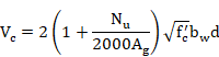
Where Nu/Ag is expressed in psi.
If section is subjected to a tensile force so that the tensile stress is less than 500 psi:

If section is
subjected to a tensile force so that the tensile stress exceeds 500 psi, it is
assumed ![]() .
.
The calculated result for both element ends is stored in the CivilFEM results file as the parameter VC:
VC Shear strength provided by concrete.
![]()
7) Calculating the shear strength provided by shear reinforcement. The strength provided by shear reinforcement (Vs) is calculated with the following expression:
![]()
where:
![]() area of the cross-section
of shear reinforcement.
area of the cross-section
of shear reinforcement.
s spacing of the stirrups measured along the longitudinal axis.
The calculated result for both element ends is stored in the CivilFEM results file as the parameter VS:
VS Shear strength provided by transverse reinforcement.
![]()
8) Calculating the nominal shear strength of the section. The nominal shear strength (Vn) is the sum of the provided by concrete and by the shear reinforcement:
![]()
This nominal strength as well as its ratio with the design shear are stored in the CivilFEM results file as the parameters:
VN Nominal shear strength.
![]()
CRTVN Ratio of the design shear force (Vu) to the resistance Vn.
![]()
If the strength provided by concrete is null and the shear reinforcement is not defined in the section, then Vn=0 and the criterion will be equal to –1.
9) Obtaining shear criterion. The section will be valid for shear if the following condition is satisfied:
![]()
f strength reduction factor of the section, (0.85 for shear and torsion).
Therefore, the shear criterion for the validity of the section is defined as follows:
![]()
For each element, this value is stored in the CivilFEM results file as the parameter CRT_TOT.
If the strength provided by concrete is null and the shear
reinforcement is not defined in the section, then ![]() , and the criterion will be equal to 2100.
, and the criterion will be equal to 2100.
The ![]() value is stored in CivilFEM results file as the parameter VFI.
value is stored in CivilFEM results file as the parameter VFI.
11-B.9.2 Torsion Checking
Torsion checking of elements is done according to ACI-318, with f=0.85.
11-B.9.3 Combined Shear and Torsion Checking
For checking sections subjected to shear force and concomitant torsional moment, the same procedure as for the ACI-318 code is followed, with f=0.85.
11-B.9.4 Shear Design
The shear design according to AASHTO Specific Standards for Highway Bridges follows these steps:
1) Obtaining material strength properties. These properties are obtained from the material properties associated with each transverse cross section and for the active time, (see ~CFMP command).
The required data are the following:
![]() specified compressive strength of concrete.
specified compressive strength of concrete.
![]() specified yield strength of reinforcement.
specified yield strength of reinforcement.
2) Obtaining geometrical data of the section. Section geometrical requirements must be defined within CivilFEM database, (~CSECDMS command). Required data for shear designing are the following:
![]() area of concrete section.
area of concrete section.
3) Obtaining geometrical parameters depending on specified code. Geometrical parameters used for shear designing must be defined within the CivilFEM database, (see ~SECMDF command). The required data are the following:
![]() web width or diameter
of the circular section, (parameter BW_VY or BW_VZ of ~SECMDF
command).
web width or diameter
of the circular section, (parameter BW_VY or BW_VZ of ~SECMDF
command).
d distance from the extreme compressed fiber to the centroid of the longitudinal tensile reinforcement in Y, (for circular sections, this must not be less than the distance from the extreme compressed fiber to the centroid of the tensile reinforcement in the opposite half of the member), (parameter D_Y or D_Z of ~SECMDF command).
Section 11-A.7 “Previous Considerations to Shear and Torsion Calculation” provides detailed information on how to calculate the required data for each code and valid section.
4) Obtaining reinforcement data of the section. In shear reinforcement designing, it is possible to define the angle a between the reinforcement and the longitudinal axis of the member. This angle must be stored in the shear reinforcement data of each element, (parameter ALPHA of ~RNFDEF and ~RNFMDF commands). If this angle is equal to zero or is not defined, a=90º. Other data concerning the reinforcements are ignored.
5) Obtaining forces and moments acting on the section. The shear force that acts on the section, as well as the concomitant axial force, is obtained from the CivilFEM results file (.RCV).
Force Description
![]() Design shear force in Y
Design shear force in Y
6) Calculating the shear strength provided by concrete. First, we calculate the shear strength provided by concrete (Vc) with the following expression:
![]()
where:
![]() square root of specified compressive strength of
concrete, in psi (always taken as less than 100 psi).
square root of specified compressive strength of
concrete, in psi (always taken as less than 100 psi).
For sections subject to a compressive axial force:
Where ![]() is expressed in psi.
is expressed in psi.
If section is subjected to a tensile force so that the tensile stress is less than 500 psi:

If section is
subjected to a tensile force so that the tensile stress exceeds 500 psi, it is
assumed ![]() .
.
The calculated result is stored in the CivilFEM results file for both element ends as the parameter:
VC Shear strength provided by concrete.
![]()
7) Determining the required reinforcement contribution to the shear strength. The section must satisfy the following condition to resist the shear force:
![]()
Therefore, the required shear force of the reinforcement must be:
![]()
If the required shear strength of the reinforcement does not satisfy the expression above, the section will not be designed. Consequently, the parameters for the reinforcement data will be defined as 2100. Therefore:
![]()
In this case, the element will be labeled as not designed, and the program will then advance to the following element.
Calculated results are stored in the CivilFEM results file for both element ends as the parameter:
VS Shear resistance provided by the transverse reinforcement.
![]()
8) Calculating the required reinforcement ratio. Once the required shear strength of the reinforcement has been obtained, the reinforcement can be calculated with the following expression:

Where:
![]() area of the
cross-section of the shear reinforcement.
area of the
cross-section of the shear reinforcement.
s spacing of the stirrups measured along the longitudinal axis.
The area of the designed reinforcement per unit length is stored in the CivilFEM results file for both element ends:
![]()
In this case, the element will be labeled as designed (providing the design procedure is correct for both element sections).
11-B.9.5 Torsion Design
Torsion reinforcements are designed according to ACI-318.
11-B.9.6 Combined Shear and Torsion Design
The design of sections subjected to shear force and concomitant torsional moment follows the method used for the ACI-318 code.
11-B.10 Shear and Torsion according to Code of Rules 52-101-03 and SP 63.13330.2012
11-B.10.1 Shear Checking
Shear checking according to СП 52-101-03 and СП 63.13330.2012 russian codes follows the steps below:
1) Obtaining materials strength properties. These properties are obtained from the material properties associated with each transverse cross section and for the active time, (see ~CFMP command). Those material properties should be previously defined. The required data are the following:
![]() design compressive strength of
concrete.
design compressive strength of
concrete.
![]() design tensile strength of concrete.
design tensile strength of concrete.
![]() design yield strength of longitudinal reinforcement.
design yield strength of longitudinal reinforcement.
![]() design yield strength of shear reinforcement.
design yield strength of shear reinforcement.
2) Obtaining geometrical parameters depending on specified code. The needed parameters used for shear calculations must be defined within CivilFEM database (see ~SECMDF command). Required data are the following:
b minimum width of the section over the effective depth, (parameter B_VY or B_VZ of ~SECMDF command).
![]() effective depth of
the section, (parameter D_Y or D_Z of ~SECMDF
command).
effective depth of
the section, (parameter D_Y or D_Z of ~SECMDF
command).
Section 11-A.7 “Previous Considerations to Shear and Torsion Calculation” provides detailed information on how to calculate the required data for each code and valid section.
3) Obtaining code parameters and coefficients. Specific code used for shear calculations must be defined within CivilFEM database (see ~SECMDF command). Required data are the following:
![]() coefficient for the calculation
of a concrete band (parameter PHIB1 of ~SECMDF
command). By default
coefficient for the calculation
of a concrete band (parameter PHIB1 of ~SECMDF
command). By default ![]()
4) Obtaining section reinforcement data. Data concerning reinforcements of the element section must be included within the CivilFEM database. (See ~RNFDEF and ~RNFMDF commands). Required data are the following:
![]() area of reinforcement per unit length, (parameters ASSY or ASSZ
of ~RNFDEF or ~RNFMDF
commands).
area of reinforcement per unit length, (parameters ASSY or ASSZ
of ~RNFDEF or ~RNFMDF
commands).
The reinforcement ratio may also be obtained with the following data:
![]() total area of the reinforcement legs, (parameters ASY or
ASZ of ~RNFDEF or ~RNFMDF
commands).
total area of the reinforcement legs, (parameters ASY or
ASZ of ~RNFDEF or ~RNFMDF
commands).
![]() spacing of the stirrups, (parameter S of ~RNFDEF or ~RNFMDF
commands).
spacing of the stirrups, (parameter S of ~RNFDEF or ~RNFMDF
commands).
or with the data below:
![]() spacing of the stirrups, (parameter S of ~RNFDEF or ~RNFMDF
commands).
spacing of the stirrups, (parameter S of ~RNFDEF or ~RNFMDF
commands).
f diameter of bars, (parameter PHI of ~RNFDEF or ~RNFMDF commands).
N number of reinforcement legs, (parameters NY or NZ of ~RNFDEF or ~RNFMDF commands).
5) Obtaining the section internal forces and moments. The shear force that acts on the section as well as the concomitant axial force and bending moment are obtained from the CivilFEM results file (.RCV).
Force Description
Q Design shear force
N Design axial force
M Design bending moment
6) Calculate coefficient for the effect of compressive and tensile
stress ![]()

7) Checking of a concrete band between inclined sections. The design shear (Q) must be less than or equal to the design shear resistance:
![]()
Results are written for each end in the CivilFEM results file as the following parameters:
Q1 Design shear resistance on a concrete band.
![]()
CRTQ1 Ratio of the design shear force (Q) to the resistance Q1.
![]()
8) Checking of bent elements in an inclined section. The following condition must be verified:
![]()
![]() is the shear strength of
concrete.
is the shear strength of
concrete.
![]() is the shear strength of longitudinal reinforcement.
is the shear strength of longitudinal reinforcement.
The contribution of the shear reinforcement and concrete to the shear strength is given by the following equation:
![]()
![]()
Results obtained are written for each end in the CivilFEM results file as the following parameters:
QB Shear strength of concrete
![]()
QSW Shear strength of stirrups.
![]()
Q2 Shear strength of inclined section.
![]()
CRTQ2 Ratio of the design shear force (Q) to the shear strength Q2.
![]()
If ![]() is taken as 2100.
is taken as 2100.
9) Obtaining shear criterion. The shear criterion indicates whether the section is valid for the design forces (if it is less than 1, the section satisfies the code prescriptions; whereas if it exceeds 1, the section will not be valid). Furthermore, it includes information about how close the design force is to the ultimate section strength. The shear criterion is defined as follows:
![]()
For each end, this value is stored in the CivilFEM results file as the parameter CRT_TOT.
11-B.10.2 Torsion Checking
Torsion checking according to СП 52-101-03 and СП 63.13330.2012 follows the steps below:
1) Obtaining materials strength properties. These properties are obtained from the material properties associated to the transverse cross section and for the active time, (see ~CFMP command). The required data are the following:
![]() design compressive strength of concrete.
design compressive strength of concrete.
![]() design yield strength of longitudinal reinforcement.
design yield strength of longitudinal reinforcement.
![]() design yield strength of shear reinforcement.
design yield strength of shear reinforcement.
2) Obtaining geometrical parameters depending on specified code. Geometrical parameters used for torsion calculations must be defined within CivilFEM database, (see ~SECMDF command). The required data are the following:
ZA First length of the effective torsional section.
ZB Second length of the effective torsional section.
The formulation uses Z1 and Z2, which refer to the lengths of the effective torsional section. These lengths will be defined as the most unfavorable case between:
![]()
Section 11-A.7 “Previous Considerations to Shear and Torsion Calculation” provides detailed information on how to calculate the required data for each code and valid section.
3) Obtaining reinforcement data of the section. Data concerning reinforcements of the section must be included within the CivilFEM database, (see ~RNFDEF and ~RNFMDF commands). Required data are the following:
Transverse Reinforcement
![]() area of transverse reinforcement per unit length, (parameter
AST/S of ~RNFDEF and ~RNFMDF
commands).
area of transverse reinforcement per unit length, (parameter
AST/S of ~RNFDEF and ~RNFMDF
commands).
The reinforcement ratio can also be obtained with the following data:
![]() closed stirrups area for torsion, (parameter AST of ~RNFDEF and ~RNFMDF
commands).
closed stirrups area for torsion, (parameter AST of ~RNFDEF and ~RNFMDF
commands).
s spacing of closed stirrups, (parameter ST of ~RNFDEF and ~RNFMDF commands).
Or with the following data:
s spacing of closed stirrups, (parameter ST of ~RNFDEF and ~RNFMDF commands).
![]() diameter of the closed stirrups, (parameter PHIT of ~RNFDEF and ~RNFMDF
commands).
diameter of the closed stirrups, (parameter PHIT of ~RNFDEF and ~RNFMDF
commands).
Longitudinal Reinforcement
![]() total area of the longitudinal reinforcement, (parameter
ASL of ~RNFDEF and ~RNFMDF
commands).
total area of the longitudinal reinforcement, (parameter
ASL of ~RNFDEF and ~RNFMDF
commands).
The reinforcement ratio can also be obtained with the following data:
![]() diameter of longitudinal bars, (parameter PHIL of ~RNFDEF and ~RNFMDF
commands).
diameter of longitudinal bars, (parameter PHIL of ~RNFDEF and ~RNFMDF
commands).
N number of longitudinal bars, (parameter N of ~RNFDEF and ~RNFMDF commands).
4) Obtaining section internal forces and moments. The torsional moment that acts on the section is obtained from the CivilFEM results file (.RCV).
Moment Description
T Design torsional moment
5) Calculating the maximum torsional moment that can be resisted by the torsional reinforcements. The design torsional moment (T) must be less than or equal to the design torsional resistance:
![]()

![]()
where:
![]() Area of the longitudinal reinforcement that lays on the
side of length Z1. It is assumed that the longitudinal torsional
reinforcement is distributed uniformly; therefore:
Area of the longitudinal reinforcement that lays on the
side of length Z1. It is assumed that the longitudinal torsional
reinforcement is distributed uniformly; therefore:
![]()
Its value must also satisfy the following condition:
![]()
Results are written in the CivilFEM results file for both element ends as the parameters:
TSW1 Maximum design torsional moment resisted by the stirrups.
![]()
TS1 Maximum design torsional moment resisted by the longitudinal torsional reinforcement.
![]()
TR Torsional moment resistance.
![]()
CRT_TOT Ratio of the design torsional moment to the resistance.
![]()
11-B.10.3 Combined Shear and Torsion Checking
For checking sections subjected to shear force and concomitant torsional moment, we follow the steps below:
1) Torsion checking considering a null shear force. This check is accomplished with the same steps as for the check of elements subjected to pure torsion.
2) Shear checking assuming a null torsional moment. Follows the same procedure as for the check of elements subjected to pure shear.
3) Combined shear and torsion checking. Shear checking is performed following the procedure previously explained:
![]()
The design torsional moment (T) must satisfy the following condition:
![]() )
)
Results obtained are written for each element end in the CivilFEM results file as the following parameters:
QB Shear strength of concrete
![]()
QSW Shear strength of stirrups.
![]()
Q2 Shear strength on inclined section.
![]()
CRTQ2 Ratio of the design shear force (Q) to the shear strength Q2.
![]()
If ![]() , CRTQ2 is taken as 2100.
, CRTQ2 is taken as 2100.
TSW1 Maximum design torsional moment that can be resisted by the stirrups.
![]()
TS1 Maximum design torsional moment that can be resisted by the longitudinal torsional reinforcement.
![]()
TR Resistance torsional moment.
![]()
CRTTOR Ratio of the design torsional moment to the resistance.
![]()
CRT_TOT Total criterion.

If Q2=0, CRT_TOT is taken as 2100.
11-B.10.4 Shear Design
Shear reinforcement designed according to СП 52-101-03 and СП 63.13330.2012 follows the steps below:
1) Obtaining material strength properties. These properties are obtained from the material properties associated with the transverse cross section and for the active time. Those material properties should be previously defined, (see ~CFMP command). The required data are the following:
![]() design compressive strength of concrete.
design compressive strength of concrete.
![]() design tensile strength of concrete.
design tensile strength of concrete.
![]() design yield strength of longitudinal reinforcement.
design yield strength of longitudinal reinforcement.
![]() design yield strength of shear reinforcement.
design yield strength of shear reinforcement.
2) Obtaining geometrical parameters depending on specified code. Geometrical parameters used for shear designing must be defined within the CivilFEM database, see ~SECMDF command. Required data are the following:
b minimum width of the section over the effective depth, (parameter B_VY or B_VZ of ~SECMDF command).
![]() effective depth of
the section, (parameter D_Y or D_Z of ~SECMDF
command).
effective depth of
the section, (parameter D_Y or D_Z of ~SECMDF
command).
3) Obtaining code parameters and coefficients. Specific code used for shear designing must be defined within CivilFEM database (see ~SECMDF command). Required data are the following:
![]() coefficient for the
calculation of a concrete band (parameter PHIB1 of ~SECMDF
command). By default
coefficient for the
calculation of a concrete band (parameter PHIB1 of ~SECMDF
command). By default ![]()
4) Obtaining forces and moments acting on the section. The shear force that acts on the sectionas well as the concomitant axial force and bending moment are obtained from the CivilFEM results file (.RCV).
Force Description
Q Design shear force
5) Calculate coefficient for the effect of compressive and tensile
stress ![]()
6) Checking whether the section will require shear reinforcement. First, we check whether the design shear (Q) is less than or equal to the design shear resistance of a concrete band between inclined sections (Q1):
![]()
![]()
Results are written for each end in the CivilFEM results file as the following parameters:
Q1 Design shear resistance on a concrete band.
![]()
CRTQ1 Ratio of the design shear force (Q) to the resistance Q1.
![]()
If the design shear force is greater than the design shear resistance on a concrete band, the reinforcement design will not be feasible; as a result, the parameter containing this datum will be marked with 2100. It will be:
![]()
In this case, the element will be marked as not designed, and the program will advance to the following element.
7) Calculating the maximum shear force that can be resisted by the concrete. The shear strength of concrete is determined by the following formula:
![]()
![]() is the shear strength of
concrete.
is the shear strength of
concrete.
Results obtained are written for each end in the CivilFEM results file as the following parameters:
QB Shear strength of concrete
![]()
8) Determining the contribution of the required transverse reinforcement. The section validity condition concerning shear force is:
![]()
![]() shear strength of
concrete, calculated in the previous step.
shear strength of
concrete, calculated in the previous step.
![]() shear strength of transverse reinforcement.
shear strength of transverse reinforcement.
The shear reinforcement contribution is given by the following equation:
![]()
![]()
Therefore, the reinforcement contribution should be:
![]()
Results obtained are written for each end in the CivilFEM results file as the following parameters:
QSW Shear strength of stirrups.
![]()
Q2 Shear strength on inclined section.
![]()
9) Calculating the required reinforcement ratio. Once the required shear force of the reinforcement has been obtained, the amount of reinforcement can be calculated from the equation below:
![]()
where:
![]() area of the shear reinforcement per unit length.
area of the shear reinforcement per unit length.
The area of designed reinforcement per unit length is stored in the CivilFEM results file as the parameter:
![]()
In this case, the element will be labeled as designed (provided that design process is correct for both element sections).
If it is not possible the design, the reinforcement will be marked as 2100 and the element will not be designed.
DSG_CRT Design criterion (Ok the element is designed and Not Ok the element is not designed).
11-B.10.5 Torsion Design
Torsion reinforcement design according to СП 52-101-03 and СП 63.13330.2012 follows the following steps:
1) Obtaining material strength properties. These properties are obtained from the material properties associated with the transverse cross section and for the active time, (see ~CFMP command). The required data are the following ones:
![]() design compressive strength of concrete.
design compressive strength of concrete.
![]() design yield strength
of longitudinal reinforcement.
design yield strength
of longitudinal reinforcement.
![]() design yield strength of
shear reinforcement
design yield strength of
shear reinforcement
2) Obtaining geometrical parameters depending on specified code. Geometrical parameters used for torsion calculations must be defined within the CivilFEM database, (see ~SECMDF command). The required data are the following:
ZA First length of the effective torsional section.
ZB Second length of the effective torsional section.
The formulation uses Z1 and Z2 which refer to the lengths of the effective torsional section. These lengths will be defined as the most unfavorable case between:
![]()
Section 11-A.7 “Previous Considerations to Shear and Torsion Calculation” provides detailed information on how to calculate the required data for each code and valid section.
3) Obtaining reinforcement data of the section. Longitudinal reinforcement data of the section are used for torsion design. Required data are the following:
Longitudinal Reinforcement
![]() total area of the longitudinal reinforcement, (parameter
ASL of ~RNFDEF and ~RNFMDF
commands).
total area of the longitudinal reinforcement, (parameter
ASL of ~RNFDEF and ~RNFMDF
commands).
The reinforcement ratio can also be obtained with the following data:
![]() diameter of longitudinal bars, (parameter PHIL of ~RNFDEF and ~RNFMDF
commands).
diameter of longitudinal bars, (parameter PHIL of ~RNFDEF and ~RNFMDF
commands).
N number of longitudinal bars, (parameter N of ~RNFDEF and ~RNFMDF commands).
4) Obtaining forces and moments acting on the section. The torsional moment that acts on the section is obtained from the CivilFEM results file.
Moment Description
![]() Design torsional moment
Design torsional moment
5) Calculating the required transverse reinforcement ratio. The design torsional moment (T) must be less than or equal to the design torsional resistance:
![]()
where:
![]() Maximum design torsional moment resisted by the transverse
reinforcement.
Maximum design torsional moment resisted by the transverse
reinforcement.
![]() Maximum design torsional moment resisted by the longitudinal
torsional reinforcement.
Maximum design torsional moment resisted by the longitudinal
torsional reinforcement.
The longitudinal torsional reinforcement contribution is given by the following equation:
![]()
where:
![]() Area of the longitudinal reinforcement that lays on the
side of length Z1. It is assumed that the longitudinal torsional
reinforcement is distributed uniformly, therefore:
Area of the longitudinal reinforcement that lays on the
side of length Z1. It is assumed that the longitudinal torsional
reinforcement is distributed uniformly, therefore:
![]()
The longitudinal torsional reinforcement contribution is calculated from the defined longitudinal reinforcement. Therefore, the transverse reinforcement contribution should be:
![]()
where:
![]()
The required transverse reinforcement is given by this expression:
![]()
Its value must also satisfy the following condition:
![]()
![]()
Results are written in the CivilFEM results file for both element ends as the parameters:
ASTTNEC Necessary transverse reinforcement to support the design torsional moment (T)
![]()
RNFRAT Reinforcement ratio:
![]()
If Ast/s=0, CRTRNF is taken as 2100.
6) Calculating the required longitudinal and transverse reinforcement ratio. In the previous step, the transverse reinforcement calculation starts from the defined longitudinal reinforcement. The longitudinal and transverse reinforcements are calculated from the following equations:
![]()
![]()
where:
![]() Area of the longitudinal reinforcement that lays on the
side of length Z1. It is assumed that the longitudinal torsional
reinforcement is distributed uniformly, therefore:
Area of the longitudinal reinforcement that lays on the
side of length Z1. It is assumed that the longitudinal torsional
reinforcement is distributed uniformly, therefore:
![]()
Its value must also satisfy the following condition:
![]()
Therefore, the section reinforcements are obtained from the following equation:
![]()
These section reinforcements are calculated for the possible values of Z1 and Z2:
![]()
CivilFEM obtains the neccessary reinforcements for the most unfavorable case from the possible values of Z1 and Z2.
Results of the designed longitudinal and transverse reinforcements are stored in the CivilFEM results file as the parameters:
TSW1 Maximum torsional moment resisted by the design stirrups.
![]()
TS1 Maximum torsional moment resisted by the design longitudinal torsional reinforcement.
![]()
TR Torsional moment resistance.
![]()
CRTTOR Ratio of the design torsional moment to the resistance.
![]()
ASTT Area of the designed transverse reinforcement
![]()
ASLT Area of the designed longitudinal reinforcement
![]()
If both transverse and longitudinal reinforcements are designed for both element sections, this element will be labeled as designed.
If the design is not possible, the reinforcement will be marked as 2100 and the element will not be designed.
DSG_CRT Design criterion (Ok the element is designed and Not Ok the element is not designed).
11-B.11 Shear and Torsion according to IS 456
11-B.11.1 Shear Checking
Shear checking of elements according to IS 456 follows the steps below:
1) Obtaining material strength properties. These properties are obtained from the material properties associated with each transverse cross section and for the active time, (see ~CFMP command). Those material properties should be previously defined. The required data are the following:
![]() characteristic compressive strength of concrete.
characteristic compressive strength of concrete.
![]() characteristic yield strength of reinforcement.
characteristic yield strength of reinforcement.
![]() partial safety factor for concrete.
partial safety factor for concrete.
![]() partial safety factor for reinforcement.
partial safety factor for reinforcement.
2) Obtaining geometrical data of the section. Section geometrical requirements must be defined within the CivilFEM database, (~CSECDMS commands). Required data for shear checking are the following:
![]() total cross-sectional area of the concrete section.
total cross-sectional area of the concrete section.
3) Obtaining geometrical parameters depending on code. Geometrical parameters used for shear calculations must be defined within CivilFEM database, see ~SECMDF command. Required data are the following:
![]() effective width of the
section, (parameter BW_VY or BW_VZ of ~SECMDF command).
effective width of the
section, (parameter BW_VY or BW_VZ of ~SECMDF command).
d effective depth of the section, (parameter D_Y or D_Z of ~SECMDF command).
![]() ratio of the longitudinal tensile reinforcement
extending beyond the effective depth of the considered section, except in
supports where the total area of the tensile reinforcement is used. (parameter
RHO1 of ~SECMDF command):
ratio of the longitudinal tensile reinforcement
extending beyond the effective depth of the considered section, except in
supports where the total area of the tensile reinforcement is used. (parameter
RHO1 of ~SECMDF command):
![]()
Section 11-A.7 “Previous Considerations to Shear and Torsion Calculation” provides detailed information on how to calculate the required data for each code and valid section.
4) Obtaining reinforcement data of the section. Data concerning reinforcements of the element section must be included within the CivilFEM database. (See ~RNFDEF and ~RNFMDF commands). Required data are the following:
a angle between shear reinforcement and the longitudinal axis of the member section, (parameter ALPHA of ~RNFDEF or ~RNFMDF commands).
![]() area of reinforcement per unit length, (parameters AS/S of ~RNFDEF
or ~RNFMDF commands).
area of reinforcement per unit length, (parameters AS/S of ~RNFDEF
or ~RNFMDF commands).
The reinforcement ratio may also be obtained with the following data:
![]() total area of the reinforcement legs, (parameter AS of ~RNFDEF
or ~RNFMDF commands).
total area of the reinforcement legs, (parameter AS of ~RNFDEF
or ~RNFMDF commands).
s spacing of the stirrups, (parameter S of ~RNFDEF or ~RNFMDF commands).
or with the data below:
s spacing of the stirrups, (parameter S of ~RNFDEF or ~RNFMDF commands).
f diameter of bars, (parameter PHI of ~RNFDEF or ~RNFMDF commands).
N number of reinforcement legs, (parameter N of ~RNFDEF or ~RNFMDF commands).
5) Obtaining the section internal forces and moments. The shear force that acts on the section as well as the concomitant axial force are obtained from the CivilFEM results file (.RCV).
Force Description
![]() Design shear force
Design shear force
![]() Concomitant axial force
Concomitant axial force
6) Calculating the nominal shear stress. The nominal shear stress is calculated by the following expression:
![]()
This stress is written for each end of the element in the CivilFEM results file as:
TAOV Shear strength
![]()
7) Checking of the maximum shear stress. The nominal shear stress must be less than or equal to the maximum shear stress:
![]()
where ![]() is given in Table 20 according to the concrete type:
is given in Table 20 according to the concrete type:

Results are stored for each end in the CivilFEM results file as the following parameters:
TCMAX Maximum shear stress.
![]()
CRTCMAX Ratio of the nominal shear stress to the shear maximum stress.
![]()
8) Calculating the shear resistance of the section. The shear resistance is calculated as the sum of the resistance provided by the concrete and the shear reinforcement:
![]()
where:
![]() shear resistance of the section
shear resistance of the section
![]() concrete contribution
to the shear resistance
concrete contribution
to the shear resistance
![]() shear reinforcement
contribution to the shear resistance
shear reinforcement
contribution to the shear resistance
The concrete contribution to the resistance is:
![]()
where tc is given in Table 19 according to the concrete type and the amount of the longitudinal tension reinforcement:

For members subjected to axial compression Pu, the design shear strength of concrete, given in Table 19, shall be multiplied by the following factor:
![]()
The reinforcement contribution to the shear resistance shall be calculated as:
![]()
![]() total cross sectional area of the shear reinforcement
total cross sectional area of the shear reinforcement
s spacing of the stirrups along the axis of the member
Results are stored for each end in the CivilFEM results file as the following parameters:
TC Design shear stress.
![]()
VUC Contribution of concrete to the shear resistance.
![]()
VUS Contribution of shear reinforcement to the shear resistance.
![]()
VUT Design shear resistance of the section.
![]()
CRVUT Ratio of the design shear force (Vu) to the shear resistance Vut.
![]()
If ![]() , CRVUT is taken as 2100.
, CRVUT is taken as 2100.
9) Obtaining shear criterion. The shear criterion indicates whether the section is valid or not for the design forces (if it is less than 1, the section satisfies the code prescriptions, whereas if it exceeds 1, the section will not be valid). Furthermore, it includes information about how close is the design force from the ultimate section strength. The shear criterion is defined as follows:
![]()
For each end, this value is stored in the CivilFEM results file as the parameter CRT_TOT.
A value of 2100 for this criterion would mean that Vut are equal to zero.
11-B.11.2 Axial and Bending with combined Shear and Torsion Checking
The axial and bending with combined shear and torsion checking according to IS 456 follows the steps below:
1) Obtaining material strength properties. These properties are obtained from the material properties associated with the transverse cross section and for the active time, (see ~SECMDF command).
2) Obtaining of the geometrical parameters of the section. Geometrical parameters of the section must be defined within the CivilFEM database, (see ~SECDMS command).
3) Obtaining geometrical parameters depending on specified code. Geometrical parameters used for torsion calculations must be defined within CivilFEM database, (see ~SECMDF command). The required data are the following:
![]() effective width of the
section, (parameter BW_VY or BW_VZ of ~SECMDF command).
effective width of the
section, (parameter BW_VY or BW_VZ of ~SECMDF command).
d effective depth of the section, (parameter D_Y or D_Z of ~SECMDF command).
![]() ratio of the longitudinal tensile reinforcement
extending beyond the effective depth of the considered section, except in
supports where the total area of the tensile reinforcement is used. (parameter RHO1 of ~SECMDF command):
ratio of the longitudinal tensile reinforcement
extending beyond the effective depth of the considered section, except in
supports where the total area of the tensile reinforcement is used. (parameter RHO1 of ~SECMDF command):
![]()
![]() ,
, ![]() center to center distances between
corner bars situated between transversal stirrups, measured along the width and
the flange of the section respectively (Y1 and Z1 parameters of the ~SECMDF
command).
center to center distances between
corner bars situated between transversal stirrups, measured along the width and
the flange of the section respectively (Y1 and Z1 parameters of the ~SECMDF
command).
Section 11-A.7 “Previous Considerations to Shear and Torsion Calculation” provides detailed information on how to calculate the required data for each code and valid section.
4) Obtaining reinforcement data of the section. Data concerning reinforcements of the section must be included within CivilFEM database, (see ~RNFDEF and ~RNFMDF commands). Required data are the following:
Longitudinal Bending Reinforcement
It is obtained from the bending reinforcement distribution of the section (see ~RNFDEF and ~RNFMDF commands)
Transverse Shear Reinforcement
a angle between the shear reinforcement and the longitudinal axis of the member section, (parameter ALPHA of ~RNFDEF or ~RNFMDF commands).
![]() area of transverse reinforcement per unit length,
(parameter AS/S of ~RNFDEF and ~RNFMDF commands).
area of transverse reinforcement per unit length,
(parameter AS/S of ~RNFDEF and ~RNFMDF commands).
The reinforcement ratio may also be obtained with the following data:
![]() total area of the reinforcement legs, (parameter AS of ~RNFDEF
or ~RNFMDF commands).
total area of the reinforcement legs, (parameter AS of ~RNFDEF
or ~RNFMDF commands).
s spacing of the stirrups, (parameter S of ~RNFDEF or ~RNFMDF commands).
or with the data below:
s spacing of the stirrups, (parameter S of ~RNFDEF or ~RNFMDF commands).
f diameter of bars, (parameter PHI of ~RNFDEF or ~RNFMDF commands).
N number of reinforcement legs, (parameters NY or NZ) of ~RNFDEF or ~RNFMDF commands).
TransverseTorsional Reinforcement
![]() area of transverse reinforcement per unit length, (parameter
AST/S of ~RNFDEF and ~RNFMDF commands).
area of transverse reinforcement per unit length, (parameter
AST/S of ~RNFDEF and ~RNFMDF commands).
The reinforcement ratio can also be obtained with the following data:
![]() closed stirrups area for torsion, (parameter AST of ~RNFDEF
and ~RNFMDF commands).
closed stirrups area for torsion, (parameter AST of ~RNFDEF
and ~RNFMDF commands).
s spacing of closed stirrups, (parameter ST of ~RNFDEF and ~RNFMDF commands).
Or with the data below:
s spacing of closed stirrups, (parameter ST of ~RNFDEF and ~RNFMDF commands).
![]() diameter of the closed stirrups, (parameter PHIT of ~RNFDEF
and ~RNFMDF commands).
diameter of the closed stirrups, (parameter PHIT of ~RNFDEF
and ~RNFMDF commands).
Longitudinal Shear Reinforcement
This reinforcement will be ignored.
5) Obtaining section internal forces and moments. The forces and moments that acts on the section are obtained from the CivilFEM results file (.RCV).
Force/Moment Description
![]() Design shear force
Design shear force
![]() Design torsional moment
Design torsional moment
![]() Concomitant axial force
Concomitant axial force
![]() Concomitant bending moment
Concomitant bending moment
6) Calculating the equivalent shear. Equivalent shear shall be calculated from the following formula:
![]()
Where Ve is the equivalent shear force.
7) Calculating the equivalent nominal shear stress. The equivalent nominal shear stress shall be calculated from the following formula:
![]()
Results are written in the CivilFEM results file for both element ends as the parameters:
TAOVE Nominal shear stress
![]()
8) Checking with the maximum shear stress. The equivalent nominal shear stress must be less than or equal to the maximum shear stress:
![]()
where tc max is given in Table 20 according to the type of concrete:
Results are stored for each end in the CivilFEM results file as the following parameters:
TCMAX Maximum shear stress.
![]()
CRTCMAX Ratio of the nominal shear stress to the maximum shear stress.
![]()
9) Checking whether the section will require transverse reinforcement. Transverse reinforcement will not be required if the equivalent nominal shear stress is less than or equal to the maximum shear stress:
![]()
where tc is given in Table 19 according to the concrete type and the amount of the longitudinal tension reinforcement:

Results are stored for each end in the CivilFEM results file as the following parameters:
ATT Area of the necessary transverse reinforcement.

CRTATT Ratio of the area of the necessary transverse reinforcement to the area of the defined transverse reinforcement (sum of shear and torsional transverse reinforcement).

10) Calculating the transverse reinforcement required. If the equivalent nominal stress exceeds the maximum shear stress, the necessary transverse reinforcement will be calculated with the following expression:

ATT Area of the necessary transverse reinforcement

CRTATT Ratio of the area of the necessary transverse reinforcement to the area of the defined transverse reinforcement (sum of shear and torsional transverse reinforcement).

If the shear and torsional transverse reinforcement is zero, Ass/s+Ast/s=0, the criterion is taken as 2100.
11) Checking of the longitudinal reinforcement. We check if the defined longitudinal bending reinforcement resists an equivalent bending moment given by the formula:
![]()
where
![]() equivalent bending moment
equivalent bending moment
![]() increment due to torsional moment:
increment due to torsional moment:

D overall depth
This equivalent moment is used in the axial bending checking (in the direction defined in the command argument). For further information about this calculation procedure, see chapters about axial load and biaxial bending of the Theory Manual.
The calculation results are stored in the CivilFEM results file for both element ends as the parameters:
MT increment of the bending moment due to torsional moment
![]()
MEL equivalent bending moment
![]()
CRTASL Ratio of the forces and moments that acts on the section to the ultimate forces and moments.
![]()
12) Obtaining total criterion. The criterion of the combined axial, bending, shear and torsional checking is obtained from the enveloping of the partial criterions. If it is less than 1, the section is valid; if it exceeds 1, the section is not valid:
CRT_TOT = Max (CRTCMAX; CRTATT; CRTASL)
This value is stored in the CivilFEM results file for both element ends as the parameter CRT_TOT.
A value of 2100 for this criterion indicates that the shear and torsion transverse reinforcements have not been defined.
11-B.11.3 Shear Design
Shear reinforcement design according to IS 456 follows the steps below:
1) Obtaining material strength properties. These properties are obtained from the material properties associated with the transverse cross section and for the active time (see ~CFMP command). The required data are the following:
![]() characteristic compressive strength of concrete.
characteristic compressive strength of concrete.
![]() characteristic yield strength of reinforcement.
characteristic yield strength of reinforcement.
![]() partial safety factor for concrete.
partial safety factor for concrete.
![]() partial safety factor for reinforcement.
partial safety factor for reinforcement.
2) Obtaining section geometrical data. Section geometrical requirements must be defined within CivilFEM database, (~CSECDMS command). Required data for shear designing are the following:
![]() total cross-sectional area of the concrete section.
total cross-sectional area of the concrete section.
3) Obtaining geometrical parameters depending on specified code. Geometrical parameters used for shear designing must be defined within the CivilFEM database, see ~SECMDF command. Required data are the following ones:
![]() effective width of the
section, (parameter BW_VY or BW_VZ of ~SECMDF command).
effective width of the
section, (parameter BW_VY or BW_VZ of ~SECMDF command).
d effective depth of the section, (parameter D_Y or D_Z of ~SECMDF command).
![]() ratio of the tensile reinforcement extending beyond the
effective depth of the considered section, except in supports where the total
area of the tensile reinforcement is used. (parameter RHO1 of ~SECMDF
command):
ratio of the tensile reinforcement extending beyond the
effective depth of the considered section, except in supports where the total
area of the tensile reinforcement is used. (parameter RHO1 of ~SECMDF
command):
![]()
Section 11-A.7 “Previous Considerations to Shear and Torsion Calculation” provides detailed information on how to calculate the required data for each code and valid section.
4) Obtaining reinforcement data of the section. In shear reinforcement design, it is possible to define the angle a between the reinforcement and the longitudinal axis of the member. This angle should be included in the reinforcement definition of each element, (parameter ALPHA of ~RNFDEF and ~RNFMDF commands). If this angle is null or it is not defined, a=90º. Other reinforcement data are ignored.
5) Obtaining forces and moments acting on the section. The shear force that acts on the section as well as the concomitant axial force and bending moment are obtained from the CivilFEM results file (.RCV).
Force Description
![]() Design shear force
Design shear force
![]() Concomitant
axial force
Concomitant
axial force
6) Calculating the nominal shear stress. The nominal shear stress is calculated from the following expression:
![]()
This stress is written for each end in the CivilFEM results file as:
TAOV Shear strength
![]()
7) Checking of the maximum shear stress. The nominal shear stress must be less than or equal to the maximum shear stress:
![]()
where tc max is given in Table 20 according to the concrete type:
Results are stored for each end in the CivilFEM results file as the following parameters:
TCMAX Maximum shear stress.
![]()
CRTCMAX Ratio of the nominal shear stress to the shear maximum stress.
![]()
If the nominal shear stress is greater than the maximum shear stress, the reinforcement design will not be possible; therefore, the parameter where the reinforcement amount is stored will be defined as 2100.
![]()
In this case, the element will be labeled as not designed, advancing then to the following element end.
8) Determining the required transverse reinforcement contribution to the shear strength. The shear resistance is calculated as the sum of the resistance provided by the concrete and the resistance provided by the shear reinforcement:
![]()
where:
![]() design shear force
design shear force
![]() shear resistance of the section
shear resistance of the section
![]() concrete contribution
to the shear strength
concrete contribution
to the shear strength
![]() shear reinforcement
contribution to the shear strength
shear reinforcement
contribution to the shear strength
Therefore, the shear reinforcement contribution shall be:
![]()
The concrete contribution to the strength is:
![]()
where tc is given in Table 19 according to the concrete type and the amount of the longitudinal tension reinforcement:

For members subjected to axial compression Pu, the design shear strength of concrete, given in Table 19, shall be multiplied by the following factor:
![]()
For each element end, the Vus value is included in the CivilFEM results file as the parameter:
VUS reinforcement design shear force
![]()
9) Calculating the required reinforcement ratio. The resistance contribution of the shear reinforcement is calculated with the following expression:
![]()
![]() area of the cross-section of the shear reinforcement
area of the cross-section of the shear reinforcement
s spacing of the stirrups measured along the longitudinal axis
Therefore:

The area of the designed reinforcement per unit length is stored in the CivilFEM results file for both element ends:
![]()
In this case, the element will be labeled as designed (providing the design procedure is correct for both element sections).
If the reinforcement design is not possible, the reinforcement value is taken as 2100 and the element will be considered not designed.
DSG_CRT Design criterion (Ok the element is designed and NotOk the element is not designed).
11-B.11.4 Axial and Bending with Combined Shear and Torsion Design
Axial and bending with shear and torsion longitudinal and transverse reinforcement design according to IS 456 follows the following steps:
1) Obtaining material strength properties. These properties are obtained from the material properties associated to each transverse cross section and for the active time, (see ~CFMP command).
The required data are the following:
![]() characteristic compressive strength of concrete.
characteristic compressive strength of concrete.
![]() characteristic yield strength of reinforcement.
characteristic yield strength of reinforcement.
![]() partial safety factor for concrete.
partial safety factor for concrete.
![]() partial safety factor for reinforcement.
partial safety factor for reinforcement.
2) Obtaining geometrical parameters. Geometrical parameters must be defined within CivilFEM database (see ~SECMDF command).
![]() gross area of the concrete section.
gross area of the concrete section.
3) Obtaining geometrical parameters depending on specified code. Geometrical parameters used for torsion designing must be defined within the CivilFEM database, (see ~SECMDF command). The required data are the following:
![]() effective width of the
section, (parameter BW_VY or BW_VZ of ~SECMDF command).
effective width of the
section, (parameter BW_VY or BW_VZ of ~SECMDF command).
d effective depth, (parameter D_Y or D_Z of ~SECMDF command).
![]() ratio of the tensile reinforcement extending beyond the
effective depth of the considered section, except in supports where the total
area of the tensile reinforcement is used. (parameter RHO1 of ~SECMDF
command):
ratio of the tensile reinforcement extending beyond the
effective depth of the considered section, except in supports where the total
area of the tensile reinforcement is used. (parameter RHO1 of ~SECMDF
command):
![]()
Section 11-A.7 “Previous Considerations to Shear and Torsion Calculation” provides detailed information on how to calculate the required data for each code and valid section.
4) Obtaining reinforcement data of the section. In longitudinal reinforcement design, it is necessary to define the distribution of bending reinforcement. In transversal reinforcement design, it is possible to define the angle a between the reinforcement and the longitudinal axis of member can be indicated. This angle should be stored in the section data of each element, (parameter ALPHA of ~RNFDEF and ~RNFMDF commands). If this angle is null or it is not defined, a=90º. Other reinforcement data will be ignored.
5) Obtaining forces and moments acting on the section. The forces and moments that act on the section are obtained from the CivilFEM results file (.RCV):
Force/Moment Description
![]() Design shear force
Design shear force
![]() Design torsional moment
Design torsional moment
![]() Concomitant axial force
Concomitant axial force
![]() Concomitant bending moment
Concomitant bending moment
6) Calculating the equivalent shear. Equivalent shear shall be calculated from the following formula:
![]()
Where Ve is the equivalent shear force.
7) Calculating the equivalent nominal shear stress. The equivalent nominal shear stress shall be calculated from the following formula:
![]()
Results are written in the CivilFEM results file for both element ends as the parameters:
TAOVE Nominal shear stress
![]()
8) Checking with the maximum shear stress. The equivalent nominal shear stress must be less than or equal to the maximum shear stress:
![]()
where tc max is given in Table 20 according to the type of concrete:

Results are stored for each end in the CivilFEM results file as the following parameters:
TCMAX Maximum shear stress.
![]()
CRTCMAX Ratio of the nominal shear stress to the shear maximum stress.
![]()
If the nominal shear stress is greater than the maximum shear stress, the reinforcement design will not be possible; therefore the parameter for the area per unit length of the reinforcement will be taken as 2100.
![]()
9) Checking whether the section will require transverse reinforcement. This reinforcement is not required if the equivalent nominal shear stress is less than or equal to the maximum shear stress:
![]()
where tc is given in Table 19 according to the concrete type and the amount of the longitudinal tension reinforcement:
Results are stored for each end in the CivilFEM results file as the following parameters:
ATT Area of the required transverse reinforcement.
![]()
10) Calculating the required transverse reinforcement. If the equivalent nominal stress exceeds the maximum shear stress, the required transverse reinforcement will be calculated by:

ATT Area of the necessary transverse reinforcement
11) Calculating the longitudinal reinforcement amount. A check is made to ensure the defined longitudinal bending reinforcement resists an equivalent bending moment given by the formula:
![]()
where
![]() equivalent bending moment
equivalent bending moment
![]() increment due to torsional moment:
increment due to torsional moment:
D overall depth
This equivalent moment is used in the axial bending design (in the direction defined in the command argument). For further information on the calculation procedure, see chapters 11-A.3 and 11-A.4 of the Theory Manual.
The calculated results are stored in the CivilFEM results file for both element ends as the parameters:
MT increment of the bending moment due to torsional moment
![]()
MEL equivalent bending moment
![]()
REINFACT Factor to multiply the scalable longitudinal bending reinforcement to satisfy the code provisions.
If the reinforcement factor is greater than the upper reinforcement limit established by the command, the design will not be possible; therefore, the reinforcement factor is defined as 2100.
![]()
If the reinforcement design is not possible at both ends, the reinforcement value is taken as 2100 and the element will be considered not designed.
DSG_CRT Design criterion (Ok the element is designed and NotOk the element is not designed).