

10-A.1 Scope
For checking steel structures according to Eurocode 3 in CivilFEM, it is possible to check structures composed by welded or rolled shapes under axial forces, shear forces and bending moments in 3D.
The calculations made by CivilFEM correspond to the recommendations of Eurocode 3 Design of Steel Structures Part 1-1 General Rules for Building, sections.
10-A.2 Checking Types
With CivilFEM it is possible to accomplish the following check and analysis types:
|
· Checking for sections subjected to: |
||
|
|
ENV 1993-1-1:1992 |
EN 1993-1-1:2005 |
|
- Tension |
Art. 5.4.3 |
Art. 6.2.3 |
|
- Compression |
Art. 5.4.4 |
Art. 6.2.4 |
|
- Bending |
Art. 5.4.5 |
Art. 6.2.5 |
|
- Shear force |
Art. 5.4.6 |
Art. 6.2.6 |
|
- Bending and Shear |
Art. 5.4.7 |
Art. 6.2.8 |
|
- Bending and axial force |
Art. 5.4.8 |
Art. 6.2.9 |
|
- Bending, shear and axial force |
Art. 5.4.9 |
Art. 6.2.10 |
|
· Checking for buckling: |
||
|
|
ENV 1993-1-1:1992 |
EN 1993-1-1:2005 |
|
- Compression members with constant cross-section |
Art. 5.5.1 |
Art. 6.3.1 |
|
- Lateral-torsional buckling of beams |
Art. 5.5.2 |
Art. 6.3.2 |
|
- Members subjected to bending and axial tension |
Art. 5.5.3 |
N/A |
|
- Members subjected to bending and axial compression |
Art. 5.5.4 |
Art. 6.3.3 |
10-A.3 Valid Element Types
The valid element types supported by CivilFEM are the following 2D and 3D ANSYS link and beam elements:
|
2D Link |
LINK1 |
|
3D Link |
LINK8 |
|
3D Link |
LINK10 |
|
2D Beam |
BEAM3 |
|
3D Beam |
BEAM4 |
|
3D Tapered Unsymmetrical Beam |
BEAM44 |
|
2D Tapered Elastic Unsymmetrical Beam |
BEAM54 |
|
2D Plastic Beam |
BEAM23 |
|
3D Thin-walled Beam |
BEAM24 |
|
3D Elastic Straight Pipe |
PIPE16 |
|
3D Plastic Straight Pipe |
PIPE20 |
|
3D Finite Linear Strain Beam |
BEAM188 |
|
3D Quadratic Linear Strain Beam |
BEAM189 |
Furthermore, it is possible to check solid sections captured from 2D or 3D models if the cross section is classified as “structural steel”.
10-A.4 Valid Cross-Section Types
Valid cross-sections supported by CivilFEM for checks according to Eurocode 3 are the following:
All rolled shapes included in the program libraries (see the hot rolled shapes library and ~SSECLIB command).
The following welded beams: double T shapes, U or channel shapes, T shapes, box, equal and unequal legs angles and pipes. (~SSECDMS commands).
Structural steel sections defined by plates (command ~SSECPLT), shapes from solid sections captured from 2D or 3D models in which the transverse cross section is classified as “structural steel”.
CivilFEM considers the above sections as sections composed of plates; for example, an I-section is composed by five plates: four flanges and one web. These cross sections are therefore adapted to the method of analysis of Eurocode 3. Obviously circular sections cannot be decomposed into plates, so these sections are analyzed differently.
10-A.5 Reference Axis
With checks according to Eurocode 3, CivilFEM includes three different coordinate reference systems. All of these systems are right-handed:
1. CivilFEM Reference Axis. (XCF, YCF, ZCF).
2. Cross-Section Reference Axis. (XS, YS, ZS).
3. Eurocode 3 Reference Axis. (Code axis). (XEC3, YEC3, ZEC3).
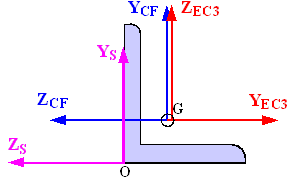
Figure 10-A.5‑1 Axis Orientation in Beam Sections
For the Eurocode 3 axis system:
The system origin coincides with the CivilFEM axis origin.
XEC3 axis coincides with CivilFEM X-axis.
YEC3 axis is the relevant axis for bending and its orientation is defined by the user. (~MEMBPRO and ~CHKSTL commands).
ZEC3 axis is perpendicular to the plane defined by X and Y axis, to ensure a right-handed system.
To define this reference system, the user must indicate which direction of the CivilFEM axis (-Z, -Y, +Z or +Y) coincides with the relevant axis for positive bending. The user may define this reference system with the commands: ~MEMBPRO, when defining member properties for Eurocode 3 and ~CHKSTL when checking according to this code. However, in case of any contradiction, the definition considered will be the one established with the ~MEMBPRO command and the one introduced through the ~CHKSTL command will be neglected. In conclusion, the code reference system coincides with that of CivilFEM, but it is rotated a multiple of 90 degrees, as demonstrated below.
Table 10-A.5‑1
|
Relevant Axis for Bending in CivilFEM Reference System |
Angle of Rotation (in clockwise) of Eurocode 3 Reference System respect to the CivilFEM Reference System |
|
- ZCF |
90 º (Default value) |
|
- YCF |
180 º |
|
+ ZCF |
270 º |
|
+ YCF |
0 º |
10-A.6 Data and Results used by CivilFEM
CivilFEM uses the following data and result groups for checks according to
Eurocode 3:
Data corresponding to sections: properties and dimensions of gross, net and effective sections; characteristics and dimensions of section plates.
Member properties.
Material properties.
Forces and moments in the section.
Checking results.
10-A.6.1 Sections Data
Eurocode 3 considers the following data set for the section:
- Gross section data
- Net section data
- Effective section data
- Data pertaining to the section and plates class.
Gross section data correspond to the nominal properties of the cross-section.
For the net section, only the area is considered. This area is calculated by subtracting the holes for screws, rivets and other holes from the gross section area. (The area of holes is introduced through the parameter AHOLES in ~SECMDF command).
Effective section data and section and plates class data are obtained in the checking process according to the effective width method. For class 4 cross-sections, this method subtracts the non-resistance zones for local buckling. However, for cross-sections of a lower class, the sections are not reduced for local buckling.
The initial required data for the Eurocode 3 module includes the gross section data in user units and the CivilFEM or section axis. The program calculates the effective section data and class data and stores them in CivilFEM’s results file, in user units and in the CivilFEM or section axis. The data can be listed and plotted with the ~PLLSSTL, ~PLCSEC3 and ~PRSTL commands.
In the following tables, the section data used in Eurocode 3 are shown:
Table 10-A.6‑1 Common data for gross, net and effective sections
|
Description |
Data |
|
Input data: 1.- Height 2.- Web thickness 3.- Flanges thickness 4.- Flanges width 5.- Distance between flanges 6.- Radius of fillet (Rolled shapes) 7.- Toe radius (Rolled shapes) 8.- Weld throat thickness (Welded shapes) 9.- Web free depth
|
H Tw Tf B Hi r1 r2 a d |
|
Output data |
(None) |
Table 10-A.6‑2 Gross section data
|
Description |
Data |
Reference axis |
|
Input data: 1.- Depth in Y 2.- Depth in Z 3.- Cross-section area 4.- Moments of inertia for torsion 5.- Moments of inertia for bending 6.- Product of inertia 7.- Elastic resistant modulus 8.- Plastic resistant modulus 9.- Radius of gyration 10.- Gravity center coordinates 11.- Extreme coordinates of the perimeter
12.- Distance between GC and SC in Y and in Z 13.- Warping constant 14.- Shear resistant areas 15.- Torsional resistant modulus 16.- Moments of inertia for bending about U, V 17.- Angle Y->U or Z->V
|
Tky tkz A It Iyy, Izz Izy Wely, Welz Wply, Wplz iy, iz Ycdg, Zcdg Ymin, Ymax, Zmin, Zmax Yms, Zms Iw Yws, Zws Xwt Iuu, Ivv a |
CivilFEM CivilFEM
CivilFEM CivilFEM CivilFEM CivilFEM CivilFEM CivilFEM Section Section
Section
CivilFEM CivilFEM Principal CivilFEM |
|
Output data: |
(None) |
|
Table 10-A.6‑3 Net section data
|
Description |
Data |
|
Input data: 1.- Gross section area 2.- Area of holes |
Agross Aholes |
|
Output data: 1.- Net Cross-section area |
Anet |
* The section holes are introduced as a cross section property
The effective section depends on the section geometry and on the forces and moments that are applied to it. Consequently, for each element end, the effective section is calculated.
Table 10-A.6‑4 Effective section data
|
Description |
Data |
Reference axis |
|
Imput data: |
(None) |
|
|
Output data: 1.- Cross-section area 2.- Moments of inertia for bending 3.- Product of inertia 4.- Elastic resistant modulus 5.- Gravity center coordinates 6.- Distance between GC and SC in Y and in Z 7.- Warping constant 8.- Shear resistant areas |
Aeff Iyyeff, Izzeff Izyeff Wyeff, Wzeff Ygeff, Zgeff Ymseff, Zmseff Iw Yws, Zws |
CivilFEM CivilFEM CivilFEM Section Section
CivilFEM |
Table 10-A.6‑5 Data referred to the section plates
|
Description |
Data |
|
Input data: 1.- Plates number 2.- Plate type: flange or web (for the relevant axis of bending) 3.- Union condition at the ends: free or fixed 4.- Plate thickness 5.- Coordinates of the extreme points of the plate (in Section axis)
|
N Pltype Cp1, Cp2 t Yp1, Yp2, Zp1, Zp2 |
|
Output data: 6.- Reduction factors of the plates at each end 7.- Plates class |
Rho1, Rho2 Cl |
10-A.6.2 Member Properties
For Eurocode 3 checking, the data set used at member level are shown in the following table. All the data are stored with the section data in user units and in the CivilFEM reference axis. This data is defined as the parameters:
- L, K, KW, C1, C2, C3, BETAMY, BETAMZ, BETAMLT, PSIVEC, CFBUCKXY and CFBUCKXZ (for ENV 1993-1-1:1992)
- L, K, KW, C1, C2, C3, CMY, CMZ, CMLT, CFBUCKXY and CFBUCKXZ (for EN 1993-1-1:2005)
of ~MEMBPRO command.
Table 10-A.6‑6 Member Properties
|
Description |
ENV 1993-1-1:1992 |
EN 1993-1-1:2005 |
|
Input data: |
|
|
|
1.- Unbraced length of member (global buckling). Length between lateral restraints (lateral-torsional buckling) |
L |
L |
|
2.- Effective length factors |
k, kw |
k, kw |
|
3.- Lateral buckling factors, depending on the load and restraint conditions |
C1, C2, C3 |
C1, C2, C3 |
|
4.- Equivalent uniform moment factors for flexural buckling |
BetaMy, BetaMz |
CMy, CMz |
|
5.- Equivalent uniform moment factors for lateral-torsional buckling |
BetaMlt |
CMLt |
|
6.- Reduction factor for vectorial effects |
PsiVec |
N/A |
|
7.- Buckling factors for planes XZ and YZ (Effective buckling length for plane XY =L*Cfbuckxy ) (Effective buckling length for plane XZ =L*Cfbuckxz ) |
Cfbuckxy, Cfbuckxz |
Cfbuckxy, Cfbuckxz |
10-A.6.3 Material Properties
For Eurocode 3 checking, the following material properties are used:
Table 10-A.6‑7 Material properties
|
Description |
Property |
|
Steel yield strength |
Fy(th) |
|
Ultimate strength |
Fu(th) |
|
Partial safety factors |
gM0 gM1 gM2 |
|
Elasticity modulus |
E |
|
Poisson coefficient |
n |
|
Shear modulus |
G |
10-A.6.4 Forces and Moments
The forces and moments necessary for the checking are obtained from the CivilFEM results file for the selected load step and substep. CivilFEM performs the necessary operations to convert the data to Eurocode 3 units system, axis and criteria. The program also makes the necessary sign conversions to satisfy the code criterion (compressive forces and stresses are positive). Internally, CivilFEM analyzes in accordance with code guidelines.
ANSYS forces and moments depend on the option selected by the user in the CLASSMOD argument of the ~CHKSTL command. If the selected option is partial, the calculation of the cross-section class is accomplished with the same forces and moments used in code checking (default option). Otherwise, if the selected option is full, all the forces and moments are considered in the calculation of the cross-section class, independent of the checking type.
The partial forces and moments sets, considered in each type of external load, are shown in the following table. The forces and moments represented in the top of the table refer to the Eurocode 3 axis (relevant axis for bending YY) and to the Eurocode 3 signs criterion (in general, compressive force is positive, except for tension and bending + axial tension, where the tensile force is considered positive). These abbreviations listed are those used by the code.
Table 10-A.6‑8 Forces and moments
|
External Load |
Nsd |
Vsd |
Vysd |
Vzsd |
Msd |
Mysd |
Mzsd |
Note |
|
Tension |
FX |
|
|
|
|
|
|
Tens.+ |
|
Compression |
-FX |
|
|
|
|
|
|
Cmp.+ |
|
Bending moment |
|
|
|
|
MY |
|
|
|
|
Bending moment |
|
|
|
|
MZ |
|
|
|
|
Shear |
|
FY |
|
|
|
|
|
|
|
Shear |
|
FZ |
|
|
|
|
|
|
|
Bending + Shear |
|
|
|
FZ |
|
MY |
|
|
|
Bending + Shear |
|
|
FY |
|
|
|
MZ |
|
|
Bi-axial bending |
-FX |
|
|
|
|
MY |
MZ |
Cmp.+ |
|
Bending and axial force |
-FX |
|
|
|
|
MY |
|
Cmp.+ |
|
Bending and axial force |
-FX |
|
|
|
|
|
MZ |
Cmp.+ |
|
Bending + axial + shear |
-FX |
|
FY |
FZ |
|
MY |
MZ |
Cmp.+ |
|
Buck. resis. Cmp. members |
-FX |
|
|
|
|
|
|
Cmp.+ |
|
Lateral-torsional buckling |
|
|
|
|
MY |
|
|
|
|
Lateral-torsional buckling |
|
|
|
|
MZ |
|
|
|
|
Bend. & axial tension buck. |
FX |
|
|
|
|
MY |
|
Tens.+ |
|
Bend. & axial tension buck. |
FX |
|
|
|
|
|
MZ |
Tens.+ |
|
Bend. & ax. Comp. buck. |
-FX |
|
|
|
|
MY |
|
Cmp.+ |
|
Bend. & ax. Comp. buck. |
-FX |
|
|
|
|
|
MZ |
Cmp.+ |
10-A.6.5 Checking Final Results
The ultimate objective is to check if the code conditions for each type of external load are fulfilled.
In general, for every type of external force, the condition required by the code in a section is the following:

The numerators of the condition are the forces and moments in the section: the axial force and the bending moments in Y and in Z axis. In some cases, these forces and moments are modified by correction factors that depend on the type of external load as well as the presence of shear forces.
The denominators include the design resistances to each of the forces and moments in the cross-section. These terms are calculated in a specific way for each type of external load and for each cross-section class. Additionally, the section class depends on the cross-section type and the internal forces and moments.
CivilFEM stores the results for each element end in an alternative in the CivilFEM results file (.RCV). These results can be retrieved with the corresponding alternative number using the command ~CFSET.
The available results data for each checking type are described in the tables included in the following sections corresponding to the different checking types executed by the program.
10-A.7 Checking Process
The checking process includes the evaluation of the following expression:
 for ENV 1993-1-1:1992
 for EN 1993-1-1:2005
Evaluation steps:
1. Read the checking type requested by the user.
2. Default checking type: Bending, shear and axial force.
3. Read the CivilFEM axis to be considered as the relevant axis for bending so that it coincides with the Y axis of Eurocode 3. In CivilFEM, by default, the principle bending axis that coincides with the +Y axis of Eurocode 3 is the –Z.
4. The following operations are necessary for each selected element:
a) Obtain material properties of the element stored in CivilFEM
database and calculate the rest of the properties needed for checking:
Properties obtained from CivilFEM database:
Calculated properties:
Epsilon, material coefficient:
![]()
b) Obtain the cross-section data corresponding to the element.
c) Initialize values of the effective cross-section.
d) Initialize reduction factors of section plates and the rest of plate parameters necessary for obtaining the plate class.
e) If necessary for the type of check (check for buckling), calculate the critical forces and moments of the section for buckling: elastic critical forces for the XY and XZ planes and elastic critical moment for lateral-torsional buckling. (See section: Calculation of critical forces and moments).
f) Obtain internal forces and moments (NSd, Vy.Sd, Vz.Sd, Mx.Sd, My.Sd, Mz.Sd for ENV 1993-1-1:1992 and NEd, Vy.Ed, Vz.Ed, Mx.Ed, My.Ed, Mz.Ed for EN 1993-1-1:2005) within the section.
g) Specific section checking according to the type of external load. The specific check includes:
1. If necessary, selecting the forces and moments considered for the determination of the section class and used for the checking process.
2. Obtaining the cross-section class and calculating the effective section properties (See Section: General Processing of Sections).
3. Checking the cross-section according to the external load and its class by calculating the following criteria: Crt_TOT, Crt_N, Crt_Mx and Crt_My.
h) Recording the results.
10-A.7.1 General Processing of Sections. Section Class and Reduction Factors Calculation.
Sections, according to Eurocode 3, are made up by plates. These plates can be classified according to:
5. Plate function: webs and flanges in Y and Z axis, according to the considered relevant axis of bending.
6. Plate union condition: internal plates or outstand plates.
For sections included in the program libraries, the information above is defined for each plate. CivilFEM classifies plates as flanges or webs according to their axis and provides the plate union condition for each end. Ends can be classified as fixed or free (a fixed end is connected to another plate and free end is not).
For checking the structure for safety, Eurocode 3 classifies sections as one of four possible classes:
|
Class 1 |
Cross-sections which can form a plastic hinge with the rotation capacity required for plastic analysis. |
|
Class 2 |
Cross-sections which can reach their plastic moment resistance, but have limited rotation capacity. |
|
Class 3 |
Cross-sections for which the stress in the extreme compression fiber of the steel member can reach the yield strength, but local buckling is liable to prevent the development of the plastic moment resistance. |
|
Class 4 |
Cross-sections for which it is necessary to make explicit allowances for the effects of local buckling when determining their moment resistance or compression resistance. |
The cross-section class is the highest (least favorable) class of all of its elements: flanges and webs (plates). First, the class of each plate is determined according to the limits of Eurocode 3. The plate class depends on the following:
1. The geometric width to thickness ratio with the plate width properly corrected according to the plate and shape type.
GeomRat = Corrected_Width / thickness
The width correction consists of subtracting the zone that does not contribute to buckling resistance in the fixed ends. This zone depends on the shape type of the section. Usually, the radii of the fillet in hot rolled shapes or the weld throats in welded shapes determine the deduction zone. The values of the corrected width that CivilFEM uses for each shape type include:
· Welded Shapes:
Double T section:
Internal webs or flanges:
Corrected width = d
d Web free depth
Outstand flanges:
|
Corrected width |
|
|
|
|
Where:
|
B |
Flanges width |
|
Tw |
Web thickness |
|
|
Radius of fillet |
T section:
Internal webs or flanges:
Corrected width = d
Outstand flanges:
Corrected width = ![]()
C section:
Internal webs or flanges:
Corrected width = d
Outstand flanges:
|
Corrected width |
B for ENV 1993-1-1:1992 |
|
|
|
L section:
Corrected width = ![]()
l1, l2 Angle flange width
Box section:
Internal webs:
Corrected width = H
H Height
Internal flanges:
Corrected width ![]()
Tw Web thickness
Circular hollow section
Corrected width = H
· Rolled Shapes:
Double T section:
Internal webs or flanges:
Corrected width = d
d Web free depth
Outstand flanges:
Corrected width ![]()
B Flanges width
T Section:
Internal webs or flanges:
Corrected width = d
Outstand flanges:
Corrected width ![]()
C Section:
Internal webs or flanges:
Corrected width = d
Outstand flanges:
Corrected width = B
L Section:
Corrected width ![]()
l1, l2 Angle flange width
Box section:
Internal webs:
Corrected width = d
Internal flanges:
Corrected width ![]()
Tf Flanges thickness
Pipe section:
Corrected width = H
2. The limit listed below for width to thickness ratio. This limit depends on the material parameter e and the normal stress distribution in the plate section. The latter value is given by the following parameters: a, Y, and k0, and the plate type, internal or outstand; the outstand case depends on if the free end is under tension or compression.
Limit (class) ![]()
![]()
![]()
where:
|
a |
Compressed length / total length |
|
y |
s2/s1 |
|
k0 |
Buckling factor |
|
s1 |
The higher stress in the plate ends. |
|
s2 |
The lower stress in the plate ends. |
A linear stress distribution on the plate is assumed.
The procedure to determine the section class is as follows:
1. Obtain stresses at first plate ends from the stresses applied on the section, properly filtered according to the check type requested by the user.
2. Calculate the parameters: a, Y and k0
For internal plates:
|
|
ENV 1993-1-1:1992 |
EN 1993-1-1:2005 |
|
|
|
|
|
|
|
|
|
|
|
|
|
|
|
|
For outstand plates with an absolute value of the stress at the free end greater than the corresponding value at the fixed end:
For ![]()
![]() (ENV 1993-1-1:1992 and EN 1993-1-1:2005)
(ENV 1993-1-1:1992 and EN 1993-1-1:2005)
For ![]()
![]() = infinite
= infinite
For outstand plates with an absolute value of the stress at the free end lower than the corresponding value at the fixed end:
For ![]()
![]() (ENV 1993-1-1:1992 and EN 1993-1-1:2005)
(ENV 1993-1-1:1992 and EN 1993-1-1:2005)
For ![]()
![]() (ENV 1993-1-1:1992 and EN 1993-1-1:2005)
(ENV 1993-1-1:1992 and EN 1993-1-1:2005)
For ![]()
![]() = infinite
= infinite
Cases in which k0 = infinite are not included in Eurocode 3. With these cases, the plate is considered to be practically in tension and it will not be necessary to determine the class. These cases have been included in the program to avoid errors, and the value k0=infinite has been adopted because the resultant plate class is 1 and the plate reduction factor is r = 1 (the same values as if the whole plate was in tension). The reduction factor is used later in the effective section calculation.
3. Obtain the limiting proportions as functions of: a, Y and k0 and the plate characteristics (internal, outstand: free end in compression or tension).
ENV 1993-1-1:1992:
Internal plates:
|
|
for |
|
|
for |
|
|
for |
|
|
for |
|
|
for |
|
|
for |
Outstand plates, free end in compression:
|
|
for rolled shapes |
|
|
for welded shapes |
|
|
for rolled shapes |
|
|
for welded shapes |
|
|
for rolled shapes |
|
|
for welded shapes |
Outstand plates, free end in tension:
|
|
for rolled shapes |
|
|
for welded shapes |
|
|
for rolled shapes |
|
|
for welded shapes |
|
|
for rolled shapes |
|
|
for welded shapes |
EN 1993-1-1:2005:
Internal plates:
|
|
for |
|
|
for |
|
|
for |
|
|
for |
|
|
for |
|
|
for |
Outstand plates, free end in compression:
|
|
|
|
|
|
Outstand plates, free end in tension:
|
|
|
|
|
|
Above is the general equation used by the program to obtain the limiting proportions for determining plate classes. In addition, plates of Eurocode 3 may be checked according to special cases.
For example:
In sections totally compressed:
a = 1; Y = 1 for all plates
In sections under pure bending:
a = 0.5; Y= -1 for the web
a = 1; Y = 1 for compressed flanges
4. Obtain the plate class:
|
If |
|
GeomRat |
< Limit(1) |
Plate Class = 1 |
|
If |
Limit(1) £ |
GeomRat |
< Limit(2) |
Plate Class = 2 |
|
If |
Limit(2) £ |
GeomRat |
< Limit(3) |
Plate Class = 3 |
|
If |
Limit(3) £ |
GeomRat |
|
Plate Class = 4 |
Repeat these steps (1,2,3,4) for each section plate.
5. Assign of the highest class of the plates to the entire section.
In tubular sections, the section class is directly determined as if it were a
unique plate, with GeomRat and the Limits calculated as follows:
6. GeomRat = outer diameter/ thickness.
![]()
![]()
![]()
For class 4 sections, the section resistance is reduced, using the effective width method.
For each section plate, the effective lengths at both ends of the plate and the reduction factors r1 and r2 are calculated. These factors relate the length of the effective zone at each plate end to its width.
Effective_length_end 1 = ![]()
Effective_length_end
2 = ![]()
The following formula from Eurocode 3 has been implemented for this process:
![]()
1. Internal plates:
For ![]() (Both ends compressed)
(Both ends compressed)
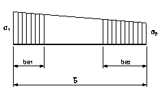
Figure 10-A.7‑1 Internal plates
![]()
![]()
![]()
![]()
![]()
![]() corrected plate width
corrected plate width
plate_width = real plate width
For ![]() (end 1 in compression and end 2 in tension)
(end 1 in compression and end 2 in tension)

Figure 10-A.7‑2
![]()
![]()
![]()
![]()
![]()
2. Outstand plates:
For ![]() (Both ends in compression: end 1 fixed, end 2 free)
(Both ends in compression: end 1 fixed, end 2 free)

Figure 10-A.7‑3
![]()
![]()
![]()
For ![]() (end
1 fixed and in tension, end 2 free and in compression)
(end
1 fixed and in tension, end 2 free and in compression)
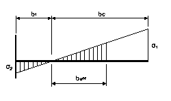
Figure 10-A.7‑4
![]()
![]()
![]()
For ![]() (end 1 fixed and in compression, end 2 free and in tension)
(end 1 fixed and in compression, end 2 free and in tension)
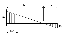
Figure 10-A.7‑5
![]()
![]()
![]()
If end 2 is the fixed end, the values r1 and r2 are switched.
The global reduction factor r is obtained by as follows:
ENV 1993-1-1:1992:
For ![]()
![]()
For ![]()

EN 1993-1-1:2005:
For internal compression elements
For ![]()

For ![]()
![]()
For outstands compression elements:
For ![]()
For ![]()
![]()
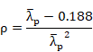
Both Eurocode define ![]() as the plate slenderness given by:
as the plate slenderness given by:
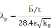
where:
![]() = corrected
plate width
= corrected
plate width
t = relevant thickness
e = material parameter
k0 = buckling factor
To determine effective section properties, three steps are followed:
1. Effective widths of flanges are calculated from factors a and Y; these factors are determined from the gross section properties. As a result, an intermediate section is obtained with reductions taken in the flanges only.
2. The resultant section properties are obtained and factors a and Y are calculated again.
3. Effective widths of webs are calculated so that the finalized effective section is determined. Finally, the section properties are recalculated once more.
The recalculated section properties are included in the effective section data table. Checking can be accomplished with the gross, net or effective section properties, according to the section class and checking type.
Each checking type follows a specific procedure that will be explained in the following sections.
10-A.7.2 Checking of Members in Axial Tension
Corresponds to chapter 5.4.3 in ENV 1993-1-1:1992 and chapter 6.2.3 in EN 1993-1-1:2005.
1. Forces and moments selection.
The forces and moments considered for this checking type are:
![]() Design value of the axial force (positive if tensile, element not
processed if compressive).Represented as NSd in ENV 1993-1-1:1992 and NEd in EN 1993-1-1:2005.
Design value of the axial force (positive if tensile, element not
processed if compressive).Represented as NSd in ENV 1993-1-1:1992 and NEd in EN 1993-1-1:2005.
2. Class definition and effective section properties calculation.
For this checking type, the section class is always 1 and the considered
section is either the gross or net section.
3. Criteria calculation.
For members under axial tension, the general criterion Crt_TOT is
checked at each section. This criterion coincides with the axial criterion Crt_N.
![]()
where Nt.Rd is the design tension resistance of the cross-section, taken as the smaller value of:
|
|
plastic design strength of the gross cross-section |
|
|
ultimate design strength of the net cross-section |
4. Output results are written in the CivilFEM results file (.RCV) as an alternative. Checking results: criteria and variables are described in the following table:
Table 10-A.7‑1 Checking of Members in Axial Tension
|
Result |
Concepts |
Description |
|
NSD |
|
Design value of the tensile force (ENV 1993-1-1:1992). |
|
NED |
|
Design value of the tensile force (EN 1993-1-1:2005). |
|
NTRD |
|
Design tensile strength of the cross-section. |
|
CRT_N |
|
Axial criterion. |
|
CRT_TOT |
|
Eurocode 3 global criterion. |
|
NPLRD |
|
Design plastic strength of the gross cross-section. |
|
NURD |
|
Ultimate design strength |
10-A.7.3 Checking of Members in Axial Compression
Corresponds to chapter 5.4.4 in ENV 1993-1-1:1992 and chapter 6.2.4 in EN 1993-1-1:2005.
1.
Forces and moments selection.
The forces and moments considered for this checking type are:
![]() Design value of the axial force (positive if compressive, element
not processed if tensile). Represented as NSd in ENV 1993-1-1:1992 and NEd in EN 1993-1-1:2005.
Design value of the axial force (positive if compressive, element
not processed if tensile). Represented as NSd in ENV 1993-1-1:1992 and NEd in EN 1993-1-1:2005.
2.
Class definition and effective section properties
calculation.
The section class is determined by the general processing of the section with
the previously selected forces and moments if the selected option is partial or
with all the forces and moments if the selected option is full. The entire
calculation process is accomplished with the gross section properties.
3.
Criteria calculation.
For members in axial compression, the general criterion Crt_TOT is
checked at each section. This criterion coincides with the axial criterion Crt_N:
![]()
where Nc.Rd is the design compression resistance of the cross-section
Class 1,2 or 3 cross-sections:
![]() design plastic resistance of the gross section
design plastic resistance of the gross section
Class 4 cross sections:
ENV 1993-1-1:1992:
![]() design local buckling resistance of the cross-section
design local buckling resistance of the cross-section
EN 1993-1-1:2005:
![]()
4. Output results written in the CivilFEM results file (.RCV) as an alternative. Checking results: criteria and variables are described at the following table.
Table 10-A.7‑2 Checking of Members in Axial Compression
|
Result |
Concepts |
Description |
|
NSD |
|
Design axial force (ENV 1993-1-1:1992). |
|
NED |
|
Design axial force (EN 1993-1-1:2005). |
|
NCRD |
|
Design compression strength of the cross-section. |
|
CRT_N |
|
Axial criterion. |
|
CRT_TOT |
|
Eurocode 3 global criterion. |
|
CLASS |
|
Section Class. |
|
AREA |
|
Area of the section (Gross or Effective). |
10-A.7.4 Checking of Members under Bending Moment
Corresponds to chapter 5.4.5 in ENV 1993-1-1:1992 and chapter 6.2.5 in EN 1993-1-1:2005.
1. Forces and moments selection.
The forces and moments considered for this checking type are:
![]() Design value of the bending
moment along the relevant axis for bending. Represented as MSd in ENV 1993-1-1:1992 and MEd in EN 1993-1-1:2005.
Design value of the bending
moment along the relevant axis for bending. Represented as MSd in ENV 1993-1-1:1992 and MEd in EN 1993-1-1:2005.
2. Class definition and effective section properties calculation.
The section class is determined by the general processing of the section with
the previously selected forces and moments if the selected option is partial or
with all the forces and moments if the selected option is full. The entire calculation
process is accomplished with the gross section properties.
3. Criteria calculation.
For members subjected to a bending moment in the absence of shear force, the
following condition is checked at each section:
4. Output results are written in the CivilFEM results file (.RCV) as an alternative. Checking results: criteria and variables are described in the following table.
![]()
![]() design value of the bending moment
design value of the bending moment
![]() design moment resistance of the cross-section
design moment resistance of the cross-section
Class 1 or 2 cross-sections:
![]()
Class 3 cross sections:
![]()
Class 4 cross sections:
ENV 1993-1-1:1992:
![]()
EN 1993-1-1:2005:
![]()
Table 10-A.7‑3 Checking of Members under Bending Moment
|
Result |
Concepts |
Description |
|
MSD |
|
Design value of the bending moment (ENV 1993-1-1:1992). |
|
MED |
|
Design value of the bending moment (EN 1993-1-1:2005). |
|
MCRD |
|
Design moment resistance of the cross-section. |
|
CRT_M |
|
Bending criterion. |
|
CRT_TOT |
|
Eurocode 3 global criterion. |
|
CLASS |
|
Section Class. |
|
W |
|
Used section modulus (Elastic, Plastic or Effective). |
10-A.7.5 Checking of Members under Shear Force
Corresponds to chapter 5.4.6 in ENV 1993-1-1:1992 and chapter 6.2.6 in EN 1993-1-1:2005.
1. Forces and moments selection.
The forces and moments considered for this checking type are:
![]() Design value of the shear force perpendicular to the
relevant axis of bending. Represented as VSd in ENV 1993-1-1:1992 and VEd in EN 1993-1-1:2005.
Design value of the shear force perpendicular to the
relevant axis of bending. Represented as VSd in ENV 1993-1-1:1992 and VEd in EN 1993-1-1:2005.
2. Class definition and effective section properties calculation.
For this checking type, the section class is always 1 and the effective section
is the gross section.
3. Criteria calculation.
With members under shear force, the following condition is checked at each
section:
![]()
where:
|
|
design value of the shear force |
|
|
design plastic shear resistance: |
|
|
shear area, obtained subtracting from the
gross area the summation of the flanges areas: |
Modifications to the previous computation of ![]() are as follows:
are as follows:
a. Rolled I and H sections, load parallel to web:
![]()
b. Rolled channel sections, load parallel to web:
![]()
EN 1993-1-1:2005 specifies additional cases for the calculation of ![]() :
:
· Rolled I and H sections with load parallel to web:
![]() but not less than η
but not less than η ![]()
· Rolled T shaped sections with load parallel to web:
![]()
Where:
|
h |
h = 1.2 for steels with fy = 460 MPa h = 1.0 for steels with fy > 460 MPa |
|
hw |
Web depth |
|
tw |
Web thickness |
4. Output results are written in the CivilFEM results file (.RCV) as an alternative. Checking results: criteria and variables are described in the following table.
Table 10-A.7‑4 Checking of Members under Shear Force
|
Result |
Concepts |
Description |
|
VSD |
|
Design value of the shear force (ENV 1993-1-1:1992). |
|
VED |
|
Design value of the shear force (EN 1993-1-1:2005). |
|
VPLRD |
|
Design plastic shear resistance. |
|
CRT_S |
|
Shear criterion. |
|
CRT_TOT |
|
Eurocode 3 global criterion. |
|
CLASS |
|
Section Class. |
|
S_AREA |
Av |
Shear area. |
10-A.7.6 Checking of Members under Bending Moment and Shear Force
Corresponds to chapter 5.4.7 in ENV 1993-1-1:1992 and chapter 6.2.8 in EN 1993-1-1:2005.
1. Forces and moments selection.
The forces and moments considered for this checking type are:
![]() Design value of the shear
force perpendicular to the relevant axis of bending. Represented as VSd
in ENV 1993-1-1:1992 and VEd in EN
1993-1-1:2005.
Design value of the shear
force perpendicular to the relevant axis of bending. Represented as VSd
in ENV 1993-1-1:1992 and VEd in EN
1993-1-1:2005.
![]() Design value of the bending
moment along the relevant axis of bending. Represented as MSd in ENV 1993-1-1:1992 and MEd in EN 1993-1-1:2005.
Design value of the bending
moment along the relevant axis of bending. Represented as MSd in ENV 1993-1-1:1992 and MEd in EN 1993-1-1:2005.
2. Class definition and effective section properties calculation.
The section class is determined by the general processing of the sections with
the previously selected forces and moments if the selected option is partial or
with all the forces and moments if the selected option is full. The entire
calculation is accomplished with gross section properties.
3. Criteria calculation.
For members subjected to bending moment and shear force, the following
condition is checked at each section:
![]()
Where:
![]() design
resistance moment of the cross-section, reduced by the presence of shear.
design
resistance moment of the cross-section, reduced by the presence of shear.
The reduction for shear is applied if the design value of the shear force exceeds 50% of the design plastic shear resistance of the cross-section; written explicitly as:
![]()
The design resistance moment is obtained as follows:
ENV 1993-1-1:1992:
a) For cross-sections with equal flanges, bending about the major axis (rolled or welded double T sections, channel sections and tubular rectangular sections):

b) For other cases the yield strength is reduced as follows:
![]()
EN 1993-1-1:2005:
c) For double T cross-sections with equal flanges, bending about the major axis:
![]()
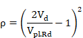
d) For other cases the yield strength is reduced as follows:
![]()
If Vd >Vpl,rd then ρ = 1. For this case:
![]()
Note: This reduction of the yield strength fy is applied to the entire section. Eurocode 3 only requires the reduction to be applied to the shear area, and therefore, it is a conservative simplification.
For both cases, MV.Rd is the smaller value of either MV.Rd or MC.Rd.
MC.Rd is the design moment resistance of the cross-section, calculated according to the class.
4. Output results are written in the CivilFEM results file (.RCV) as an alternative. Checking results: criteria and variables are described in the following table.
Table 10-A.7‑5 Checking of Members under Bending Moment and Shear Force
|
Result |
Concepts |
Description |
|
MSD |
|
Design value of the bending moment (ENV 1993-1-1:1992). |
|
VSD |
|
Design value of the shear force (ENV 1993-1-1:1992). |
|
MED |
|
Design value of the bending moment (EN 1993-1-1:2005). |
|
VED |
|
Design value of the shear force (EN 1993-1-1:2005). |
|
MVRD |
|
Reduced design resistance moment of the cross-section. |
|
CRT_BS |
|
Bending and Shear criterion. |
|
CRT_TOT |
|
Eurocode 3 global criterion. |
|
CLASS |
|
Section Class. |
|
S_AREA |
|
Shear area. |
|
W |
|
Used section modulus (Elastic, Plastic or Effective). |
|
VPLRD |
|
Design plastic shear resistance. |
|
RHO |
|
Reduction factor. |
10-A.7.7 Checking of Members under Bending Moment + Axial Force and Bi-axial Bending + Axial Force
Corresponds to chapter 5.4.8 in ENV 1993-1-1:1992 and chapter 6.2.9 in EN 1993-1-1:2005.
1. Forces and moments selection.
The forces and moments considered for this checking type are:
|
|
Design value of the axial force.
Represented as |
|
|
Design value of the bending moment along
the relevant axis of bending. Represented as |
|
|
Design value of the bending moment about
the secondary axis of bending. Represented as |
2. Class definition and effective section properties calculation.
The section class is determined by the general processing of the sections with
the previously selected forces and moments if the selected option is partial,
or with all the forces and moments if the selected option is full. These calculations
are accomplished with the gross section properties.
3. Criteria calculation.
For members subjected to bi-axial bending and in absence of shear force, the
following conditions at each section are checked:
Class 1 and 2 sections:
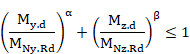
This condition is equivalent to:
![]()

![]()
Where ![]() and
and ![]() are the design moment resistances of the
cross-section, reduced by the presence of the axial force:
are the design moment resistances of the
cross-section, reduced by the presence of the axial force:


Where a and b are constants, which may take the following values:
For I and H sections:
a = 2 and b =5n ![]()
For circular tubes:
a = 2 and b =2
For rectangular hollow sections:
![]() but
but ![]()
For solid rectangles and plates (the rest of sections):
![]() (only ENV 1993-1-1:1992)
(only ENV 1993-1-1:1992)

Furthermore, EN 1993-1-1:2005 specifies that in the case of rolled shapes for I or H sections or other sections with flanges, it is not necessary to reduce the design plastic strength for bending around the y-y axis due to the axial force if the following two conditions are fulfilled:
![]()
![]()
(if it does not reach half the tension strength of the web)
The same is applicable for bending around the z-z axis due to the axial force. There is no reduction when the following condition is fulfiled (only EN 1993-1-1:2005):
![]()
In
absence of ![]() , the previous check can be reduced to:
, the previous check can be reduced to:

Condition equivalent to:

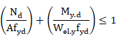
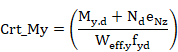
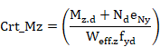
Class 3 sections (without holes for fasteners):

Condition equivalent to:
Crt_TOT = Crt_N + Crt_My + Crt_Mz £ 1

Where ![]() is the elastic resistant modulus about the
y axis and
is the elastic resistant modulus about the
y axis and ![]() is the elastic resistant modulus about the
z axis.
is the elastic resistant modulus about the
z axis.
In absence of ![]() , the above criterion becomes:
, the above criterion becomes:
Which is equivalent to:
![]()

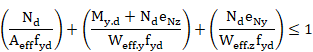
Class 4 sections:

Condition equivalent to:
![]()
Where:
|
|
effective area of the cross-section |
|
|
effective section modulus of the cross-section when subjected to a moment about the y axis |
|
|
effective section modulus of the cross-section when subjected to a moment about the z axis |
|
|
shift of the center of gravity along the y axis |
|
|
shift of the center of gravity along the z axis |
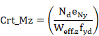
Without
![]() , the above criterion becomes:
, the above criterion becomes:
which is equivalent to:
![]()

4. Output results are written in the CivilFEM results file (.RCV) as an alternative. Checking results: criteria and variables are described in the following table.
Table 10-A.7‑6 Checking of Members under Bending Moment + Axial Force and Bi-axial Bending + Axial Force
|
Result |
Concepts |
Description |
|
NSD |
|
Design value of the axial force (ENV 1993-1-1:1992). |
|
MYSD |
|
Design value of the bending moment about Y axis (ENV 1993-1-1:1992). |
|
MZSD |
|
Design value of the bending moment about Z axis (ENV 1993-1-1:1992). |
|
NED |
|
Design value of the axial force (EN 1993-1-1:2005). |
|
MYED |
|
Design value of the bending moment about Y axis (EN 1993-1-1:2005). |
|
MZED |
|
Design value of the bending moment about Z axis (EN 1993-1-1:2005). |
|
NCRD |
|
Design compression resistance of the cross-section |
|
MNYRD |
|
Reduced design moment resistance of the cross-section about Y axis |
|
MNZRD |
|
Reduced design moment resistance of the cross-section about Z axis |
|
CRT_N |
|
Axial criterion |
|
CRT_MY |
|
Bending criterion along Y |
|
CRT_MZ |
|
Bending criterion along Z |
|
ALPHA |
α |
Alpha constant |
|
BETA |
β |
Beta constant |
|
CRT_TOT |
Crt_tot £ 1 |
Eurocode 3 global criterion |
|
CLASS |
|
Section Class |
|
AREA |
|
Area of the section utilized (Gross or Effective) |
|
WY |
|
Used section Y modulus (Elastic, Plastic or Effective) |
|
WZ |
|
Used section Z modulus (Elastic, Plastic or Effective) |
|
SIGXED |
|
Maximum longitudinal stress |
|
ENY |
|
Shift of the Z axis in Y direction |
|
ENZ |
|
Shift of the Y axis in Z direction |
|
USE_MY |
|
Modified design value of the bending moment about Y axis |
|
USE_MZ |
|
Modified design value of the bending moment about Z axis |
|
PARM_N |
n |
Parameter n |

10-A.7.8 Checking of Members under Bending, Shear and Axial Force
Corresponds to chapter 5.4.9 in ENV 1993-1-1:1992 and chapter 6.2.10 in EN 1993-1-1:2005.
1. Forces and moments selection
The forces and moments considered for this checking type are:
|
|
Design value of the axial force.
Represented as |
|
|
Design value of the shear force
perpendicular to the secondary axis of bending. Represented as |
|
|
Design value of the shear force
perpendicular to the relevant axis of bending. Represented as |
|
|
Design value of the bending moment about
the relevant axis of bending. Represented as |
|
|
Design value of the bending moment about
the secondary axis of bending. Represented as |
2. Class definition and effective section properties calculation.
The section class is determined by the general processing of the sections with
the previously selected forces and moments if the selected option is partial,
or with all the forces and moments if the selected option is full. The entire
calculation is accomplished with the gross section properties.
3. Criteria calculation.
For members subjected to bending, axial and shear force, the same conditions of
the bending +axial force and bi-axial bending are checked at each section,
reducing the design plastic resistance moment for the presence of shear force.
The shear force effect is taken into account when it exceeds 50% of the design
plastic resistance of the cross-section. In this case, both the axial and the
shear force are taken into account.
The axial force effects are included as stated in the
previous section, and the shear force effects are taken into account
considering a yield strength for the cross-section, reduced by the factor (1-r), as
follows:
![]()
where:
|
|
for |
|
|
for |
This yield strength reduction is selectively applied to the resistance of the cross-section along each axis, according to the previous conditions.
Note: The yield strength reduction is applied to the entire cross-section; however, Eurocode only requires the reduction to be applied to the shear area. Thus, it is a conservative simplification.
4. Output results are written in the CivilFEM results file (.RCV) as an
alternative. Checking results: criteria and variables are described in the
following table.
Table 10-A.7‑7 Checking of Members under Bending, Shear and Axial Force
|
Result |
Concepts |
Description |
|
NSD |
|
Design value of the axial force (ENV 1993-1-1: 1992). |
|
VZSD |
|
Design value of the shear force (ENV 1993-1-1: 1992). |
|
VYSD |
|
Design value of the shear force (ENV 1993-1-1: 1992). |
|
MYSD |
|
Design value of the bending moment about Y axis (ENV 1993-1-1: 1992). |
|
MZSD |
|
Design value of the bending moment about Z axis (ENV 1993-1-1:1992). |
|
NED |
|
Design value of the axial force (EN 1993-1-1:2005). |
|
VZED |
|
Design value of the shear force (EN 1993-1-1:2005). |
|
VYED |
|
Design value of the shear force (EN 1993-1-1:2005). |
|
MYED |
|
Design value of the bending moment about Y axis (EN 1993-1-1:2005). |
|
MZED |
|
Design value of the bending moment about Z axis (EN 1993-1-1:2005). |
|
NCRD |
|
Design compression resistance of the cross-section. |
|
MNYRD |
|
Reduced design moment Y resistance of the cross-section. |
|
MNZRD |
|
Reduced design moment Z resistance of the cross-section. |
|
CRT_N |
|
Axial criterion. |
|
CRT_MY |
|
Bending Y criterion. |
|
CRT_MZ |
|
Bending Z criterion. |
|
ALPHA |
α |
Alpha constant. |
|
BETA |
β |
Beta constant. |
|
RHO_Y |
ρ |
Reduction factor for MNYRD. |
|
RHO_Z |
ρ |
Reduction factor for MNZRD. |
|
CRT_TOT |
Crt_TOT £ 1 |
Eurocode 3 global criterion. |
|
AREA |
|
Used area of the section (Gross or Effective). |
|
WY |
|
Used section Y modulus (Elastic, Plastic or Effective). |
|
WZ |
|
Used section Z modulus (Elastic, Plastic or Effective). |
|
SIGXED |
|
Maximum longitudinal stress. |
|
ENY |
|
Shift of the Z axis in Y direction. |
|
ENZ |
|
Shift of the Y axis in Z direction. |
|
USE_MY |
|
Modified design value of the bending moment about Y axis. |
|
USE_MZ |
|
Modified design value of the bending moment about Z axis. |
|
SHY_AR |
|
Shear Y area. |
|
SHZ_AR |
|
Shear Z area. |
|
PARM_N |
n |
Parameter n. |
10-A.7.9 Checking for Buckling of Compression Members
Corresponds to chapter 5.5.1 in ENV 1993-1-1:1992 and chapter 6.3.1 in EN 1993-1-1:2005.
5. Forces and moments selection.
The forces and moments considered in this checking type are:
|
|
Design value of the axial force (positive
if compressive, otherwise element is not processed). Represented as |
6. Class definition and effective section properties calculation.
The section class is determined by the sections general processing with the
previously selected forces and moments if the selected option is partial, or
with all the forces and moments if the selected option is full. The entire
calculation is accomplished with the gross section properties.
7. Criteria calculation.
When checking the buckling of compression members, the criterion is given by:
![]()
where:
|
|
Design buckling resistance. b = 1 for class 1, 2 or 3 sections. b = |
|
|
Reduction factor for the relevant buckling mode, the program does not consider the torsional or the lateral-torsional buckling. |
The c calculation in members of constant cross-section may be determined from:

![]()
where a is an imperfection factor that depends on the buckling curve. This curve depends on the cross-section type, producing the following values for a:
Table 10-A.7‑8 Imperfection factor a for ENV 1993-1-1:1992
|
Section type |
Limits |
Buckling axis |
Buckling curve |
a |
|
Rolled I |
h/b>1.2 and tf |
y – y |
a |
0.21 |
|
Rolled I |
h/b>1.2 and tf |
z – z |
b |
0.34 |
|
Rolled I |
h/b>1.2 and 40mm<t |
y – y |
b |
0.34 |
|
Rolled I |
h/b>1.2 and 40mm<tf |
z – z |
c |
0.49 |
|
Rolled I |
h/b |
y – y |
b |
0.34 |
|
Rolled I |
h/b |
z – z |
c |
0.49 |
|
Rolled I |
tf>100mm |
y – y |
d |
0.76 |
|
Rolled I |
tf>100mm |
z – z |
d |
0.76 |
|
|
||||
|
Welded I |
tf |
y – y |
b |
0.34 |
|
Welded I |
tf |
z – z |
c |
0.49 |
|
Welded I |
tf >40mm |
y – y |
c |
0.49 |
|
Welded I |
tf >40mm |
z – z |
d |
0.76 |
|
|
||||
|
Rolled box and pipe |
- |
Any |
a |
0.21 |
|
Welded box and pipe (Using fyb) |
- |
Any |
b |
0.34 |
|
|
||||
|
Welded box in other case |
- |
Any |
b |
0.34 |
|
Welded box |
b/tf <30 |
y – y |
c |
0.49 |
|
Welded box |
h/tw <30 |
z – z |
c |
0.49 |
|
U, L and T |
- |
Any |
c |
0.49 |
Table 10-A.7‑9 Imperfection factor a for EN 1993-1-1:2005
|
Section type |
Limits |
Buckling axis |
Steel fy |
Buckling curve |
a |
|
|
Rolled I |
h/b>1.2 and t |
y – y |
< 460 MPa |
a |
0.21 |
|
|
≥ 460 MPa |
a0 |
0.13 |
||||
|
Rolled I |
h/b>1.2 and t |
z – z |
< 460 MPa |
b |
0.34 |
|
|
≥ 460 MPa |
a0 |
0.13 |
||||
|
Rolled I |
h/b>1.2 and 40mm<t |
y – y |
< 460 MPa |
b |
0.34 |
|
|
≥ 460 MPa |
a |
0.21 |
||||
|
Rolled I |
h/b>1.2 and 40mm<t |
z – z |
< 460 MPa |
c |
0.49 |
|
|
≥ 460 MPa |
a |
0.21 |
||||
|
Welded I |
h/b |
y – y |
< 460 MPa |
b |
0.34 |
|
|
≥ 460 MPa |
a |
0.21 |
||||
|
Welded I |
h/b |
z – z |
< 460 MPa |
c |
0.49 |
|
|
≥ 460 MPa |
a |
0.21 |
||||
|
Rolled I |
t>100mm |
y – y |
< 460 MPa |
d |
0.76 |
|
|
≥ 460 MPa |
c |
0.49 |
||||
|
Rolled I |
t>100mm |
z – z |
< 460 MPa |
d |
0.76 |
|
|
≥ 460 MPa |
c |
0.49 |
||||
|
|
||||||
|
Welded I |
t |
y – y |
all |
b |
0.34 |
|
|
Welded I |
t |
z – z |
all |
c |
0.49 |
|
|
Welded I |
t >40mm |
y – y |
all |
c |
0.49 |
|
|
Welded I |
t >40mm |
z – z |
all |
d |
0.76 |
|
|
|
||||||
|
Pipes
|
Hot finished |
all |
< 460 MPa |
a |
0.21 |
|
|
≥ 460 MPa |
a0 |
0.13 |
||||
|
Cold formed |
all |
all |
c |
0.49 |
||
|
Reinforced box sections |
Thick weld: a/t>0.5 b/t<30 h/tw<30 |
all |
all |
c |
0.49 |
|
|
In other case |
all |
all |
b |
0.34 |
||
|
|
||||||
|
U, T, plate |
- |
all |
all |
c |
0.49 |
|
|
|
||||||
|
L |
- |
all |
all |
b |
0.34 |
|
![]()
![]()
Where Ncr is the elastic critical force for the relevant buckling mode. (See section for Critical Forces and Moments Calculation).
In the case of angular sections, the buckling length will be taken as the highest among the buckling lengths on the Y and Z axis.
The elastic critical axial forces are calculated in the planes XY (Ncrxy) and XZ (Ncrxz) and the corresponding values of cxy and cxz , and the correspondent to the principal axis Ncru and Ncrv and the values for cu and cv taking the smaller one as the final value for c.
![]()
8. Output results are written in the CivilFEM results file (.RCV) as an alternative. Checking results: criteria and variables are described in the following table.
Table 10-A.7‑10 Checking for Buckling of Compression Members
|
Result |
Concepts |
Description |
|
NSD |
|
Design value of the compressive force (ENV 1993-1-1:1992). |
|
NED |
|
Design value of the compressive force (EN 1993-1-1:2005). |
|
NBRD |
|
Design buckling resistance of a compressed member. |
|
CRT_CB |
|
Compression buckling criterion. |
|
CRT_TOT |
|
Eurocode 3 global criterion. |
|
CHI |
|
Reduction factor for the relevant buckling mode. |
|
BETA_A |
|
Ratio of the used area to gross area. |
|
AREA |
A |
Area of the gross section. |
|
CHI_Y |
|
Reduction factor for the relevant My buckling mode. |
|
CHI_Z |
|
Reduction factor for the relevant Mz buckling mode. |
|
CHI_V |
|
Reduction factor for the principal axis V. |
|
CHI_U |
|
Reduction factor for the principal axis U. |
|
CLASS |
|
Section Class. |
|
PHI_Y |
|
Parameter Phi for bending My. |
|
PHI_Z |
|
Parameter Phi for bending Mz. |
|
PHI_V |
|
Parameter Phi for the principal axis V. |
|
PHI_U |
|
Parameter Phi for the principal axis U. |
|
LAM_Y |
|
Non-dimensional reduced slenderness for bending My. |
|
LAM_Z |
|
Non-dimensional reduced slenderness for bending Mz. |
|
LAM_V |
|
Non-dimensional reduced slenderness for the principal axis V. |
|
LAM_U |
|
Non-dimensional reduced slenderness for the principal axis U. |
|
NCR_Y |
|
Elastic critical force for the relevant My buckling mode. |
|
NCR_Z |
|
Elastic critical force for the relevant Mz buckling mode. |
|
NCR_V |
|
Elastic critical force for the principal axis V. |
|
NCR_U |
|
Elastic critical force for the principal axis U. |
|
ALP_Y |
|
Imperfection factor for bending My. |
|
ALP_Z |
αz |
Imperfection factor for bending Mz. |
10-A.7.10 Checking for Lateral-Torsional Buckling of Beams Subjected to Bending
Corresponds to chapter 5.5.2 in ENV 1993-1-1:1992 and chapter 6.3.2 in EN 1993-1-1:2005.
1. Forces and moments selection.
The forces and moments considered for this checking type are:
|
|
Design value of the bending moment about
the relevant axis of bending. Represented as |
2. Class definition and effective section properties calculation.
The section class is determined by the general processing of sections with the
previously selected forces and moments if the selected option is partial, or
with all the forces and moments if the selected option is full. The entire
calculation is accomplished with the gross section properties.
3. Criteria calculation.
When checking for lateral-torsional buckling of beams, the criterion shall be
taken as:
![]() à
à ![]()
where:
|
|
Design buckling resistance moment of a
laterally unrestrained beam. bw = 1 for class 1and 2 sections. bw = bw = |
|
cLT |
Reduction factor for lateral-torsional buckling. |
The value of cLT is calculated as:
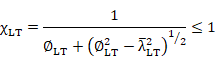
![]()
![]()
Where:
|
aLT |
is the imperfection factor for lateral-torsional buckling: aLT = 0.21 for rolled sections. aLT = 0.49 for welded sections. |
||||||||||||||||||||||||||||||||||||||||||||||||||||||||||||||||||||||||||||||||||||||||||||||||||||||||||||||||||||||||||||||||||||||||||||||||||||||||||||||||||||||||||||||||||||||||||||||||||||||||||||||||||||||||||||||
|
Mcr |
is the elastic critical moment for lateral-torsional buckling (See chapter
Table 10-A.7‑14 Checking for Lateral-Torsional Buckling of Members Subjected to Bending and Axial Compression for EN 1993-1-1:2005
Critical Forces and Moments Calculation) |
4. Output results are written in the CivilFEM results file (.RCV) as an alternative. Checking results: criteria and variables are described in the following table.
Table 10-A.7‑11 Checking for Lateral-Torsional Buckling of Beams Subjected to Bending
|
Result |
Concepts |
Description |
|
MSD |
|
Design value of the bending moment (ENV 1993-1-1:1992). |
|
MED |
|
Design value of the bending moment (EN 1993-1-1:2005). |
|
MBRD |
|
Buckling resistance moment of a laterally unrestrained beam. |
|
CRT_LT |
|
Lateral-torsional buckling criterion. |
|
CRT_TOT |
|
Eurocode 3 global criterion. |
|
CLASS |
|
Section Class. |
|
CHI_LT |
|
Reduction factor for lateral-torsional buckling. |
|
BETA_W |
|
Ratio of the used modulus to plastic modulus. |
|
WPL |
|
Plastic modulus. |
|
PHI_LT |
|
Parameter Phi for lateral-torsional buckling. |
|
LAM_LT |
|
Non-dimensional reduced slenderness. |
|
MCR |
Mcr |
Elastic critical moment for lateral-torsional buckling. |
|
ALP_LT |
|
Imperfection factor for lateral-torsional buckling. |
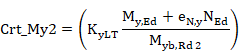
10-A.7.11 Checking Lateral-Torsional Buckling of Members Subjected to Combined Bending and Axial Tension
Corresponds to chapter 5.5.3 in ENV 1993-1-1:1992. Not available for EN 1993-1-1:2005.
1. Forces and moments selection.
The forces and moments considered for this checking type are:
|
NSd = FX |
Design value of the axial force (positive if tensile, otherwise element not processed if compressive). |
|
MSd = MY or MZ |
Design value of the bending moment about the relevant bending axis. |
2. Class definition and effective section properties calculation.
The section class is determined by the general processing of sections with the
previously selected forces and moments if the selected option is partial, or
with all the forces and moments if the selected option is full. The entire
calculation is accomplished with the gross section properties.
3. Criteria calculation.
With checking lateral-torsional buckling of members subjected to combined
bending and axial tension, the value of the axial force is multiplied by a
reduction factor yvec in order to consider the axial
force and bending moment as a vector magnitude.
The value of ![]() depends on the country where the code will be applied. That factor
is introduced as a property at member level, and typically its value is equal
to:
depends on the country where the code will be applied. That factor
is introduced as a property at member level, and typically its value is equal
to: ![]()
The stress in the extreme compression fiber is calculated as follows:
![]()
Where ![]() is the elastic section modulus for the
extreme compression fiber and Nt.Sd is the design
value of the axial tension.
is the elastic section modulus for the
extreme compression fiber and Nt.Sd is the design
value of the axial tension.
The verification equation is derived to:
![]() à
à ![]()
Where:
![]()
4. Output results are written in the CivilFEM results file (.RCV) as an alternative. Checking results: criteria and variables are described in the following table.
Table 10-A.7‑12 Art. 5.5.3 Checking Lateral-Torsional Buckling of Members Subjected to Combined Bending and Axial Tension
|
Results |
Concepts |
Description |
|
NTSD |
|
Design value of the axial tension. |
|
MSD |
|
Design value of the bending moment. |
|
MEFFSD |
|
Effective design internal moment. |
|
MBRD |
|
Buckling resistance moment of a laterally unrestrained beam. |
|
CRT_LT |
|
Lateral-torsional buckling criterion. |
|
CRT_TOT |
|
Eurocode 3 global criterion. |
|
CLASS |
|
Section Class. |
|
WCOM |
|
Elastic section modulus for the extreme compression fiber. |
|
SCOMED |
|
Net calculated stress in the extreme compression fiber. |
|
CHI_LT |
|
Reduction factor for lateral-torsional buckling. |
|
BETA_W |
|
Ratio of the used modulus to plastic modulus. |
|
WPL |
|
Plastic modulus. |
|
PHI_LT |
|
Parameter Phi for lateral-torsional buckling. |
|
LAM_LT |
|
Esbeltez adimensional reducida. |
|
MCR |
Mcr |
Elastic critical moment for lateral-torsional buckling. |
|
ALP_LT |
|
Non-dimensional reduced slenderness. |
10-A.7.12 Checking for Lateral-Torsional Buckling of Members Subjected to Bending and Axial Compression
Corresponds to chapter 5.5.4 in ENV 1993-1-1:1992 and chapter 6.3.3 in EN 1993-1-1:2005.
1. Forces and moments selection.
The forces and moments considered in this checking type are:
|
|
Design value of the axial compression (positive if compressive, otherwise element not processed if tensile). Represented as NSd in ENV 1993-1-1:1992 and NEd in EN 1993-1-1:2005. |
|
|
Design value of the bending moment about the relevant axis of bending. Represented as My.Sd in ENV 1993-1-1:1992 and My.Ed in EN 1993-1-1:2005. |
|
|
Design value of the bending moment about the secondary axis of bending. Represented as Mz.Sd in ENV 1993-1-1:1992 and Mz.Ed in EN 1993-1-1:2005. |
2. Class definition and effective section properties calculation.
The section class is determined by the general processing of sections with the
previously selected forces and moments if the selected option is partial, or
with all the forces and moments if the selected option is full. The entire
calculation is accomplished with the gross section properties.
3. Criteria calculation.
ENV 1993-1-1:1992
When checking the lateral-torsional buckling of members subjected to combined bending and axial compression, the criterion to satisfy is as follows:
![]() à Crt_TOT =
Crt_N + Crt_My + Crt_Mz £ 1
à Crt_TOT =
Crt_N + Crt_My + Crt_Mz £ 1
where:
|
Crt_TOT |
Eurocode 3 global criterion. |
|
|
Axial criterion. |
|
|
Bending criterion (principal axis). |
|
|
Bending criterion (secondary axis). |
|
|
Design buckling resistance for compression. |
|
|
Design buckling resistance moment (principal axis) |
|
|
Design buckling resistance moment (secondary axis). |
The member resistances depend on the cross-section class and on the possibility that the lateral-torsional buckling is a potential failure mode for the structure.
Members with class 1 and 2 cross-sections shall satisfy:

where:
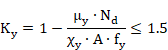
![]()
![]()
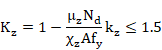
![]()
Where:
|
|
are the reduction factors defined at the section corresponding to Checking for Buckling of Compression Members. |
|
|
are equivalent uniform moment factors for flexural bending. These factors are entered as properties at member level (~MEMBPRO command). (See section Data at Member Level, factors BetaMy and BetaMz). |
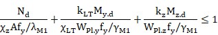
Members with Class 1 and 2 cross-sections for which lateral-torsional buckling is a potential failure mode shall satisfy:
where:
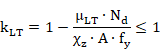
![]()
where bM.LT is an equivalent uniform moment factor for lateral-torsional buckling. This factor, as the precedent factors BetaMy and BetaMz, is introduced as a member property. (See section data at Member Level, factor BetaMlt).
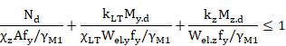
Members with Class 3 cross-sections shall satisfy:

where ![]() and
and ![]() are as for Class 1 and 2 cross-sections.
are as for Class 1 and 2 cross-sections.
![]()
![]()
Members with Class 3 cross-sections for which lateral-torsional buckling is a potential failure mode shall satisfy:
Members with Class 4 cross-sections shall satisfy:
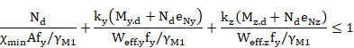
where:
|
|
are the same as for class 1 and 2
cross-sections, but use the effective area |
|
|
are the same as for class 3 cross-sections,
but add the moment |
|
|
are defined in the section corresponding to Checking of members under bending and axial force and bi-axial bending. |
Members with Class 4 cross-sections for which lateral-torsional buckling is a potential failure mode shall satisfy:

where:
|
|
is similar to class 1 and 2 cross-sections,
but uses the effective area |
|
|
is similar to class 2 cross-sections, but
adds the moment |
EN 1993-1-1:2005 and Annex B (method 2)
The following criterion will always be calculated:

Crt_1 = Crt_N1 + Crt_My1 + Crt_Mz1 £ 1
Elements without torsional buckling:
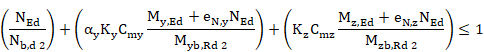
Elements which may have torsional buckling:
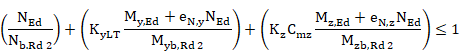
à ![]()
à
![]()
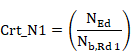
Where:
|
|
Axial force criterion 1. |
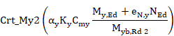
|
|
Bending moment criterion for principal axis 1. |
|
|
Bending moment criterion for secondary axis 1 |
|
Crt_TOT1 |
General criterion 1. |
|
|
Axial force criterion 2. |
|
|
Bending moment criterion 2 for principal axis without torsional buckling |
|
|
Bending moment criterion 2 for principal axis when torsional buckling is considered. |
|
|
Bending moment criterion 2 for secondary axis. |
|
|
Criterion 2 |
|
|
Global criterion. |


Where:
![]()
![]()
(![]() when torsional buckling is not considered ).
when torsional buckling is not considered ).
![]() and
and ![]() are the reduction factors defined for the section corresponding to the
check for Buckling of Compression Members.
are the reduction factors defined for the section corresponding to the
check for Buckling of Compression Members.
![]() lateral buckling factor according to 6.3.2.2.
Assumes the value of 1 for members not susceptible to torsional deformations.
lateral buckling factor according to 6.3.2.2.
Assumes the value of 1 for members not susceptible to torsional deformations.
![]() and
and ![]() shifts of the centroid of the effective
area relative to the centre of gravity of the gross section in class 4 members
for y, z axes.
shifts of the centroid of the effective
area relative to the centre of gravity of the gross section in class 4 members
for y, z axes.
![]() ,
, ![]() and
and ![]() are equivalent uniform moment factors for flexural bending. These
factors are entered as member properties at member level. (See
are equivalent uniform moment factors for flexural bending. These
factors are entered as member properties at member level. (See ![]() and
and ![]() ). These
factors may be taken from Table B.3 from Annex B of code EN 1993-1-1:2005.
). These
factors may be taken from Table B.3 from Annex B of code EN 1993-1-1:2005.
Checking Parameters:
|
Class |
A |
|
|
|
|
|
|
|
1 |
A |
|
|
0.6 |
0.6 |
0 |
0 |
|
2 |
A |
|
|
0.6 |
0.6 |
0 |
0 |
|
3 |
A |
|
|
0.8 |
1 |
0 |
0 |
|
4 |
|
|
|
0.8 |
1 |
Depending on members and stresses |
Depending on members and stresses |
Interaction Factors:
|
Class |
Section type |
|
|
|
|
1 y 2 |
I, H |
|
|
|
|
RHS |
|
|||
|
3 y 4 |
All sections |
|
|
|
where:
![]() Limited slenderness values for y-y and z-z axes, less than 1.
Limited slenderness values for y-y and z-z axes, less than 1.
![]()
4. Output results are written in the CivilFEM results file (.RCV) as an alternative. Checking results: criteria and variables are described in the following table.
Table 10-A.7‑13 Checking for Lateral-Torsional Buckling of Members Subjected to Bending and Axial Compression for ENV 1993-1-1:1992
|
Concepts |
Description |
|
|
NSD |
|
Design value of the axial compression force. |
|
MYSD |
|
Design value of the bending moment about Y axis. |
|
MZSD |
|
Design value of the bending moment about Z axis. |
|
NBRD |
|
Design compression resistance of the cross-section. |
|
MYRD |
Wply·fy/ |
Reduced design moment resistance of the cross-section about Y axis. |
|
MZRD |
Wplz·fy/ |
Reduced design moment resistance of the cross-section about Z axis. |
|
K_Y |
|
Interaction factor |
|
K_Z |
|
Interaction factor |
|
K_LT |
|
Interaction factor |
|
CRT_N |
|
Axial criterion. |
|
CRT_MY |
|
Bending Y criterion. |
|
CRT_MZ |
|
Bending Z criterion. |
|
CRT_TOT |
Crt_tot £ 1 |
Eurocode 3 global criterion. |
|
CLASS |
|
Section Class. |
|
CHIMIN |
|
Reduction factor for the relevant buckling mode. |
|
CHI_Y |
|
Reduction factor for the relevant My buckling mode. |
|
CHI_Z |
|
Reduction factor for the relevant Mz buckling mode. |
|
CHI_LT |
|
Reduction factor for lateral-torsional buckling. |
|
AREA |
|
Used area of the section (Gross or Effective). |
|
WY |
|
Used section Y modulus (Elastic, Plastic or Effective). |
|
WZ |
|
Used section Z modulus (Elastic, Plastic or Effective). |
|
ENY |
|
Shift of the Z axis in Y direction. |
|
ENZ |
|
Shift of the Y axis in Z direction. |
|
NCR_Y |
|
Elastic critical force for the relevant My buckling mode. |
|
NCR_Z |
|
Elastic critical force for the relevant Mz buckling mode. |
|
MCR |
|
Elastic critical moment for lateral-torsional buckling. |
|
ALP_Y |
|
Imperfection factor for bending My. |
|
ALP_Z |
|
Imperfection factor for bending Mz. |
|
ALP_LT |
|
Imperfection factor for lateral-torsional buckling. |
|
LAM_Y |
|
Non-dimensional reduced slenderness for bending My. |
|
LAM_Z |
|
Non-dimensional reduced slenderness for bending Mz. |
|
LAM_LT |
|
Non-dimensional reduced slenderness for lateral-torsional buckling. |
|
MU_Y |
|
Parameter Muy for bending My. |
|
MU_Z |
|
Parameter Muz for bending Mz. |
|
MU_LT |
|
Parameter MuLT for lateral-torsional buckling. |
Table 10-A.7‑14 Checking for Lateral-Torsional Buckling of Members Subjected to Bending and Axial Compression for EN 1993-1-1:2005
|
Result |
Concepts |
Description |
|
NED |
|
Design value of the axial compression force. |
|
MYED |
|
Design value of the bending moment about Y axis. |
|
MZED |
|
Design value of the bending moment about Z axis. |
|
NBRD1 |
|
Design compression resistance of the cross-section. |
|
MYRD1 |
|
Reduced design moment resistance of the cross-section about Y axis. |
|
MZRD1 |
|
Reduced design moment resistance of the cross-section about Z axis. |
|
NBRD2 |
|
Design compression resistance of the cross-section. |
|
MYRD2 |
|
Reduced design moment resistance of the cross-section about Y axis. |
|
MZRD2 |
|
Reduced design moment resistance of the cross-section about Z axis. |
|
K_Y |
|
Parameter |
|
K_Z |
|
Parameter |
|
K_LT |
|
Parameter |
|
CRT_N1 |
|
Axial criterion. |
|
CRT_MY1 |
|
Bending Y criterion. |
|
CRT_MZ1 |
|
Bending Z criterion. |
|
CRT_1 |
CRT_N1+CRT_MY1+CRT_MZ1 |
Criterion 1 |
|
CRT_N2 |
|
Axial criterion. |
|
CRT_MY2 |
|
Bending Y criterion. K= |
|
CRT_MZ2 |
|
Bending Z criterion. |
|
CRT_2 |
|
Criterion 2 |
|
CRT_TOT |
|
Eurocode 3 global criterion. |
|
CLASS |
|
Section Class. |
|
CHIMIN |
|
Reduction factor for the relevant buckling mode. |
|
CHI_Y |
|
Reduction factor for the relevant My buckling mode. |
|
CHI_Z |
|
Reduction factor for the relevant Mz buckling mode. |
|
CHI_LT |
|
Reduction factor for lateral-torsional buckling. |
|
AREA |
|
Used area of the section (Gross or Effective). |
|
WY |
|
Used section Y modulus (Elastic, Plastic or Effective). |
|
WZ |
|
Used section Z modulus (Elastic, Plastic or Effective). |
|
ENY |
|
Shift of the Z axis in Y direction. |
|
ENZ |
|
Shift of the Y axis in Z direction. |
|
NCR_Y |
|
Elastic critical force for the relevant My buckling mode. |
|
NCR_Z |
|
Elastic critical force for the relevant Mz buckling mode. |
|
MCR |
|
Elastic critical moment for lateral-torsional buckling. |
|
LAM_Y |
|
Non-dimensional reduced slenderness for bending My. |
|
LAM_Z |
|
Non-dimensional reduced slenderness for bending Mz. |
|
LAM_LT |
|
Non-dimensional reduced slenderness for lateral-torsional buckling. |
10-A.7.13 Critical Forces and Moments Calculation
The critical
forces and moments![]() ,
, ![]() and
and ![]() , are needed for the
different types of buckling checks. They are calculated based on the following
formulation:
, are needed for the
different types of buckling checks. They are calculated based on the following
formulation:
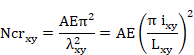

where:
|
|
Elastic critical axial force in plane XY. |
|
|
Elastic critical axial force in plane XZ. |
|
A |
Gross area. |
|
E |
Elasticity modulus. |
|
|
Member slenderness in plane XY. |
|
|
Member slenderness in plane XZ. |
|
|
Radius of gyration of the member in plane XY. |
|
|
Radius of gyration of the member in plane XZ. |
|
|
Buckling length of member in plane XY. |
|
|
Buckling length of member in plane XZ. |
The buckling length in both planes is the length between the ends restrained against lateral movement and it is obtained from the member properties, according to the following expressions:
![]()
![]()
where:
|
Cfbuckxy |
Buckling factor in plane XY. |
|
Cfbuckxz |
Buckling factor in plane XZ. |
For the calculation of the elastic critical moment for lateral-torsional buckling, Mcr, the following equation shall be used. This equation is only valid for uniform symmetrical cross-sections about the minor axis (Annex F, ENV 1993-1-1:1992). Eurocode 3 does not provide a method for calculating this moment in nonsymmetrical cross-sections or sections with other symmetry plane (angles, channel section, etc.).


where:
|
|
Elastic critical moment for lateral-torsional buckling. |
|
|
Factors depending on the loading and end restraint conditions. |
|
|
Effective length factors. |
|
E |
Elasticity modulus. |
|
|
Moment of inertia about the principal axis. |
|
|
Moment of inertia about the minor axis. |
|
L |
Length of the member between end restraints. |
|
G |
Shear modulus. |
|
|
|
|
|
Coordinate of the point of load
application. ANSYS always considers that the load is applied at the center of
gravity, therefore: |
|
|
Coordinate of the shear center. |
|
A |
Cross-section area. |
Factors C and k are read from the properties at member level (~MEBMPRO command).
The integration
of the previous equation is calculated as a summation extending to each plate.
This calculation is accomplished for each plate according to its ends
coordinates: ![]() and and
and and ![]() its thicknesses.
its thicknesses.
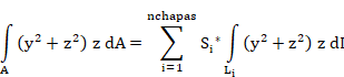
where:
![]() = thickness of plate i
= thickness of plate i
![]()
![]()
![]()
![]()
![]()
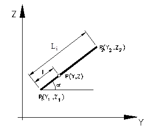
Figure 10-A.7‑6