

Arch Bridges Generator

Once user decides between BEAM or SHELL model, the following arch bridge types can be generated:
Beam Arch
- According the placement of the deck in relation to the arch provides different cases:
o Deck type (tangent & secant cases included)

o Through arch

o Tied arch

- Unlimited number of archs
- Bracings can be created between archs
SHELL Arch
- Deck type (tangent case included)
For both types:
- Symmetrical or Non-Symmetrical bridges
- Fixed or two hinged arch.
- The bridge is divided into three parts :
o Entrance or left side
o Center
o Exit or right side
All sides have straight directrix and in elevation view they are rects or parabola.
In the generated bridge 3D model all norms and conventions used in Bridges Module are kept up and, as well, all utilities for load generation are applicable.
1 ARCH BRIDGES GENERATION WINDOW
1.1 TYPOLOGIES
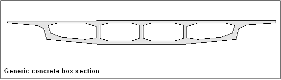
Only admissible the ones generated as CivilFEM Bridge Section, concrete box or slab type.

1.2 USING THE GENERATOR
Before launching it, user must define the following data:
- Unit System.
- Materials to be used: concrete, reinforcing & prestressing steel, etc.
- Element types for bridge structures: archs, piers and cables (if exist).
- Cross sections and thickness.
- Real constants and Beam & Shell Properties.
After that, the generator window appears with the ~BRAC, FileName command
or using the Main Menu path:
Civil Preprocessor > Bridges Prep > Predesigned bridges > Arch Bridges > Beam
Or
Civil Preprocessor > Bridges Prep > Predesigned bridges > Arch Bridges > Shell

1.3 WINDOWS FOR DATA INTRODUCTION
There are two windows, one for BEAM and another for SHELL model, the explanation for each one is in next chapter:


1.4 DATA EXPLANATION
Taking into account the next figures, all parameters are explained below:


1.4.1 GENERAL TAB
General and basic data which are constant in al model are introduced in this tab. Some parameters are different depending on Beam or Shell option.
Initial point and tolerances:
Tolerance EPS is used to avoid placing nodes too close and elements of not desired length. Tolerance EPS2 decides when arch is tangent with bottom bridge deck. Bridge deck has constant depth (as almost all cases), only one section can be selected with SecTr.
|
XLi, YLi |
Coordinates of initial left point of the bridge |
|
EPS |
Tolerance for nodes (general) |
|
EPS2 |
Tolerance for nodes (tangent arch) |
|
SecTr |
Bridge Section (constant) |
Model and mesh parameters:
|
EIType |
Deck element type (should be SOLID45) |
|
EIMat |
Deck element material |
|
SIZEV, SIZET, SIZEL, SIZEH |
Size of divisions (Bridge section) : vertical, transverse, longitudinal and holes outline |
Arch characteristics:
|
ArElType |
Arch element type |
|
ArMat |
Arch material |
|
BSArch |
Arch B&S property |
Pier characteristics:
PeSize parameter specifies the pier element edge length. Divisions are automatically calculated (rounded upward to next integer) from line lengths.
|
tPil |
Pier element type |
|
mPil |
Pier material |
|
BSPil |
Pier B&S property |
|
PeSize |
Pier element edge length |
Vertical suspension cables characteristics (only for Beam case):
|
tHT |
Vertical suspension cables element type |
|
mHT |
Vertical suspension cables material |
|
rHT |
Vertical suspension cables Real Constants |
Bracing characteristics (only for Beam case):
|
tBrac |
Bracing element type |
|
mBrac |
Bracing material |
|
BSBrac |
Bracing B&S property |
Options:
|
Symm Y/N |
If 1 Symmetric bridge (right side = left side). Default case |
|
Cables Y/N |
If 1 generate archs, piers & vertical suspension cables. If 0 only generates deck bridge. |
|
Tied Y/N |
If 1 Tied arch (BEAM). If 0 rest of types (default case) |
|
Bracing Y/N |
If 1 bracing are created between archs (only in BEAM case and if more than 2 archs are defined) |
1.4.2 LEFT TAB
In this tab all data of the left side of bridge will be defined, from the initial point to the beginning of arch. DL array indicates the separation between each terrain piers and ZTL array will define the height of each pier as shown in figure:

All parameters of this tab are valid for Beam and Shell cases.
Bridge Segment:
|
DL |
Array of lengths in the left segment |
|
PL1 |
Slope in % at the beginning of left segment |
|
ZL1 |
Height at beginning of left segment |
|
ZL2 |
Height at end of left segment |
|
ZTL |
Array of heights of left terrain piers |

1.4.3 CENTRAL TAB
This is the main tab because position of arch in relation of bridge deck will be defined here.
Bridge segment:
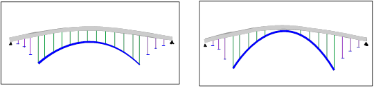
DC array indicates the distance between each pier (figure a) or between cables (figure b) or both (figure c):

|
DC |
Array of lengths in the center segment |
|
PC1 |
Slope in % at the beginning of center segment |
|
ZC1 |
Height at the beginning of center segment |
|
ZC2 |
Height at the end of center segment |

![]()
Archs:
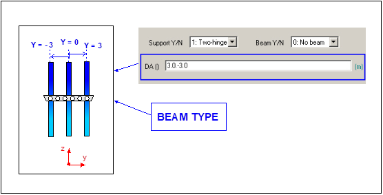
Parameters ArchWdth y ArchDiv are only valid for SHELL elements case and DA array only for BEAM. In this case unlimited number of archs can be generated and each “y” coordinate position is defined in DA array. Is very important to know where the axis origin is, in order to place the archs correctly. For Example, if DA = (3, 0,-3) archs will be generated at positions: y = 3, y = 0 & y = -3.
![]()
By changing zAL, zAR y PAL values we will obtain different positions of arch in relation of bridge deck. For tangent case EPS2 tolerance value must be modified in general tab:

For SHELL case, an error message will be displayed if arch goes through bridge deck:

|
ArchWdth |
Arch width (Shell case) |
|
ArchDiv |
Number of arch width divisions (Shell case) |
|
DA |
Array of y coordinate distances (in plan view) of each arch with bridge axis (Beam case) |
|
zAL |
Height at the beginning of arch |
|
zAR |
Height at the end of arch |
|
PAL |
Slope in % at the beginning of arch |
|
Beam Y/N |
Generation of a beam element in arch & deck intersection (Beam case) |
|
Support |
Support type: fixed or two-hinged arch |
With Beam Y/N paramenter user can create or not a beam element in arch component when intersection exists between arch and bridge deck.

Piers:
When user generates arch with shell elements, row position of piers can be chosen with parameter Prows, the maximum value depends on the number of divisions of arch width, defined in parameter ArchDiv.
|
PRows |
Array of positions of pier rows (Shell case) |

![]()
When arch is generated with beam elements, deck to arch piers position will be conditional on y arch coordinate:

For all cases, piers are always located in the bottom side of bridge deck (marked in red):

Piers are defined by two nodes: one in the bottom side of bridge deck and the other in the arch. If piers are not completely vertical is because the “y” location of nodes mentioned are different. User must modify arch location or bridge section.
1.4.4 RIGHT TAB
In this tab all data of the left side of bridge will be defined, from the initial point to the beginning of arch. DR array indicates the separation between each terrain piers and ZTR array will define the height of each pier as shown in figure:

All parameters of this tab are valid for Beam and Shell cases.
Bridge Segment:
|
DR |
Array of lengths in the right segment |
|
PR1 |
Slope in % at the beginning of right segment |
|
ZR1 |
Height at beginning of right segment |
|
ZR2 |
Height at end of right segment |
|
ZTR |
Array of heights of right terrain piers |
Related commands: