

10-D.1 Scope
The British Standard BS 5950:2000 supersedes BS 5950:1985, which has been withdrawn. BS 5950:2000 is the British Standard for the structural use of steelwork in building, widely in use in regions which experience or have experienced British influence. The purpose of this manual is to define the reach and method of implementing this method within CivilFEM.
The types of analyses considered in this standard have been developed according to the ultimate limit state in agreement with the simple and continuous design methods. Semi-continuous design and experimental verification fall beyond the scope of this specification.
The applicable cross sections for checking procedures include rolled or welded sections subjected to axial forces, shear, and bending in 2D and 3D as well as solid sections subjected to the aforementioned forces.
The calculations made by CivilFEM correspond to the design guidelines of British Standard 5950:2000 Structural use of steelwork in building: Part 1. Code of practice for design – Rolled and welded sections.
10-D.2 Checking Types
With CivilFEM it is possible to accomplish the following checking and analysis types:
· Checking of sections subjected to:
|
British Standard 5950 (2000) apt. 4.2 |
|
|
- Bending and Shear |
British Standard 5950 (2000) apt. 4.2 |
|
- Lateral Torsional Buckling |
British Standard 5950 (2000) apt. 4.3 |
|
- Axial Tension |
British Standard 5950 (2000) apt. 4.6 |
|
- Axial Compression |
British Standard 5950 (2000) apt. 4.7 |
|
- Axial Tension with Moments |
British Standard 5950 (2000) apt. 4.8.2 |
|
- Axial Compression with Moments |
British Standard 5950 (2000) apt. 4.8.3 |
10-D.3 Valid Element Types
The valid element types supported by CivilFEM are the following 2D and 3D ANSYS link and beam elements:
|
2D Link |
LINK1 |
|
3D Link |
LINK8 |
|
3D Link |
LINK10 |
|
2D Beam |
BEAM3 |
|
3D Beam |
BEAM4 |
|
3D Tapered Unsymmetrical Beam |
BEAM44 |
|
2D Tapered Elastic Unsymmetrical Beam |
BEAM54 |
|
2D Plastic Beam |
BEAM23 |
|
3D Thin-walled Beam |
BEAM24 |
|
3D Elastic Straight Pipe |
PIPE16 |
|
3D Plastic Straight Pipe |
PIPE20 |
|
3D Finite Linear Strain Beam |
BEAM188 |
|
3D Quadratic Linear Strain Beam |
BEAM189 |
Moreover, it is possible to check solid sections captured from 2D or 3D models with a transversal cross section classified as “structural steel”.
10-D.4 Valid Cross-Section Types
Valid cross-sections supported by CivilFEM for checking according to British Standard 5950:2000 are the following:
All the rolled shapes included in the program libraries (see the hot rolled shapes library and ~SSECLIB command)
The following welded beams: I shapes, U or channel shapes, T shapes, box, equal and unequal legs angles and pipes. (~SSECDMS commands).
Structural steel sections defined by plates (command ~SSECPLT). Although the code does not contemplate them explicitly, these sections can be checked following the same general criteria and procedures specified in the code. The user is responsible for accepting these criteria and procedures.
Shapes from solid sections captured from 2D or 3D models with transverse cross sections classified as “structural steel”.
CivilFEM considers the above sections as sections composed of elements (plates), for example, an I section is composed of five elements or plates: four flanges and one web. Therefore, these cross sections are adapted to the method of analysis of British Standard 5950:2000. Obviously, circular sections cannot be discomposed into elements so these sections are analyzed differently.
10-D.5 Reference Axis
With performing checks according to BS 5950:2000, CivilFEM includes three different coordinate reference systems. All of these systems are right-handed:
1. CivilFEM Reference Axes (XCF, YCF, ZCF).
2. Cross-Section Reference Axes (XS, YS, ZS).
3. BS 5950:2000 Reference Axes (Code Axes), (XBS, YBS, ZBS).

Figure 10-D.5‑1 Axis Orientation in Beam Sections
For the BS 5950:2000 axes system:
· The system origin coincides with the CivilFEM axis origin.
· The ZBS axis coincides with the CivilFEM X axis
· The XBS axis is the principal axis for bending and its orientation is defined by the user (~MEMBPRO and ~CHKSTL commands).
· The YBS axis is perpendicular to the plane defined by the X and Y-axes, in such a way as to ensure a right-handed system.
To define this reference system, the user must indicate which of the CivilFEM axis: -Z, -Y, +Z or +Y coincides with the relevant axis for positive bending. The user may define this reference system with the commands: ~MEMBPRO when defining member properties for British Standard 5950:2000 or ~CHKSTL when checking according to this code. However, in case of any contradiction, the adopted option will be the one established with ~MEMBPRO command and the one introduced through ~CHKSTL command is neglected.
10-D.6 Data and Results used by CivilFEM
The British Standard 5950:2000 considers all sections as composed of elements or plates. Therefore, there are two types of properties: those which correspond to the whole cross section and those which correspond to the individual section elements.
CivilFEM uses the following data and result groups for checking according to British Standard 5950:2000:
· Data pertaining to sections: properties and dimensions of gross, net and effective sections, characteristics and dimensions of section elements.
· Code Properties.
· Properties at member level.
· Material properties.
· Forces and moments in the section.
· Checking results.
10-D.6.1 Section Data
BS 5950:2000 considers the following data set for the cross section:
· Gross section data
· Net section data
· Effective section data
· Data concerning the section and element class.
Gross section data correspond to the nominal properties of the cross-section.
From the net section, the net area and the effective net area are considered. The net area is calculated by subtracting the area of holes for screws, rivets and other holes from the gross section area, taking into account the deduction for fastener holes according to section 3.4.4 of the code (see figures 3 and 4 of the code). The area of holes is introduced through the parameter AHOLES as a code property (see ~SECMDF command).
The effective net area is obtained from the net area, multiplying it by a coefficient Ke which depends on type of steel used. This coefficient is calculated by the program and stored together with the material properties.
Effective section data are obtained in the checking process according to the effective width method (Sect. 3.6 of BS 5950:2000). This method discounts the non-resistance zones for local buckling in class 4 cross-sections. For cross-sections of a lower class, this method does not reduce the section because of local buckling.
As an alternative method for slender cross sections calculation, a reduced design strength (ryr) may be calculated at which the cross section would be class 3 (section 3.6.5 of the code).
Section and element class data are obtained using tables 11 and 12 of BS 5950:2000 (section 3.5.2). The classification of each element is based on its width to thickness ratio and according to section type (hot-rolled or welded), element type (web or flange) and position (internal or external element). CivilFEM assumes the section class as the largest from all the elements (least favorable).
The initial required data for the BS 5950:2000 module includes the gross section data in user units and the CivilFEM axis or section axis (see the section corresponding to Reference axis in beam sections in Chapter 5 of this Manual). The data are then properly converted from the section’s axis into the BS 5950:2000 axis and the results are given in the code axis. The program calculates the effective and net section data and the class data and stores them into CivilFEM’s results file in user units and in the CivilFEM coordinate system. All of the data can be listed and plotted with ~CSLST and ~PRSTL commands.
The section data used in BS 5950:2000 is shown in the following tables:
I.- Section Dimensions
|
Description |
Data |
|
Input data: 1.- Height 2.- Web thickness 3.- Flanges thickness 4.- Flanges width 5.- Distance between flanges 6.- Radius of fillet (Rolled shapes) 7.- Toe radius (Rolled shapes) 8.- Weld throat thickness (Welded shapes) 9.- Web free depth |
H Tw Tf B Hi r1 r2 a d |
|
Output data |
(Nothing) |
I.- Gross Section Resistant Properties
|
Description |
Data |
|
Datos de entrada: 1.- Area 2.- Moments of inertia for torsion 3.- Moments of inertia for bending 4.- Product of inertia 5.- Elastic resistant modulus 6.- Plastic resistant modulus 7.- Radius of gyration 8.- Coordinates of the center of gravity
9.- Distance between GC and SC in X and in Y 10.- Distance CG to shear center along Y axis 11.- Distance CG to shear center along X axis 12.- Warping Constant 13.- Shear resistant areas 14.- Torsional resistant modulus |
A It Ixx, Iyy Ixy Wx, Wy Wpx, Wpy ix, iy Ymn, Ymx, Xmn, Xmx Xm, Ym Ys Xs Iw Yws, Xws Zwt |
|
Output Data: 1.- Shear area for major axis (X) 2.- Sv parameter for major axis (X) 3.- Shear area for minor axis (Y) 4.- Sv parameter for minor axis (X) 5.- Critical shear strength of web panel for major axis 6.- Critical shear strength of web panel for minor axis 7.- Y coordinate of plastic center 8.- X coordinate of plastic center |
Avx Svx Avy Svy Vcrx Vcry Yp Xp |
|
* The section properties listed here in are related to the BS coordinate system (XBS, YBS, ZBS) |
|
III.- Net section data
|
Description |
Data |
|
Input data: AHOLES* |
|
|
Output data: 1.- Net area 2.- Effective net area |
Ant Aneff |
|
|
|
* Deduction for holes are introduced as a code property
IV.- Effective section data
|
Description |
Data |
|
Input data: None |
|
|
Output data: 1.- Effective Area 2.- Moments of inertia for torsion 3.- Moments of inertia for Y bending 4.- Moments of inertia for X bending 5.- Elastic resistant Y modulus 6.- Elastic resistant X modulus 7.- Plastic resistant Y modulus 8.- Plastic resistant X modulus |
Aeff It Iyyeff Ixxeff Wyeff Wxeff Wpyeff Wpxeff |
|
9.- Section class 10.- Web class for shear buckling |
Cls ClsAlm |
V.- Section element data
|
Description |
Data |
|
Input data: 1.- Number of elements 2.- Element type: flange or web (for the relevant axis of bending) 3.- Union condition at the ends: free or fixed 4.- Element thickness 5.- Coordinates of the extreme points of the element (using Section axes)
|
N Pltype Cp1, Cp2 t Yp1, Yp2, Zp1, Zp2 |
|
Output data: 6.- Element class 7.- Reduction factor (for class 4 section- alternative method) 8.- Web Class |
Cl fr Webclass |
10-D.6.2 Member Properties
The data used at member level by BS 5950:2000 is shown in the following table. All the data is stored with the section data in user units and in the code coordinate system. (Parameters L, Kcx, Kcy, KLtx, KLty, mlt, mx, my, CFBUCKX, CFBUCKY, CteRob, DL, d/a and CHCKAXIS of the ~MEMBPRO command).
Table 10-D.6‑1 Member properties
|
Description |
Data |
Article |
|
Input data: 1.- Unbraced length of member 2.- Compression buckling factor for X axis 3.- Compression buckling factor for Y axis 4.- Lateral torsional buckling factor for X axis 5.- Lateral torsional buckling factor for Y axis 6.- Factors by which multiply “L” to found the length between restrictions in planes xz and yz, respectively 7.- Robertson Constant 8.- Equivalent uniform moment factor for major axis flexural bending 9.- Equivalent uniform moment factor for minor axis flexural bending 10.- Equivalent uniform moment factor for lateral torsional buckling 11.- Depth of the compression flanges lip 12.- Intermediate stiffeners depth 11.- CivilFEM Axis which is the X axis in BS 5950:2000 0: Not defined 1: -Z CivilFEM 2: +Y CivilFEM 3: +Z CivilFEM 4: -Y CivilFEM |
L Kcx Kcy Klty Cfbuckx, Cfbucky CteRob mx my mlt DL d/a CHCKAXIS |
Section 4.7.3 Section 4.7.3 Section 4.3.5
Appendix C.2 Section 4.8.3 Section 4.8.3 Section 4.3.6.6 Section 4.3.6.7 Section 4.4.5
|
10-D.6.3 Material Properties
BS 5950:2000 uses the following material properties in its checks:
Table 10-D.6‑2 Material properties
|
Properties, symbol |
|
|
Yield strength |
|
|
Tensile strength |
|
|
Design strength |
py (table 9 of BS 5950-1:2000 and table 3 of EN10113-2:1993) |
|
Material strength factor |
|
|
Modulus of elasticity |
E = 205 kN/mm2 |
|
Shear Modulus |
|
|
Poisson’s ratio |
|
|
Coefficient of linear thermal expansion |
|
|
Effective net area coefficient |
|
|
Constant є |
|
The code uses
other safety factors ![]() which depend on the type of loads and which must be used when
performing load combinations.
which depend on the type of loads and which must be used when
performing load combinations.
10-D.6.4 Forces and Moments
The forces applicable for each check are obtained from the CivilFEM results file (.RCV) for the selected load step and substep. CivilFEM will perform all the necessary conversions to conform with the units, axes and criteria of BS 5950:2000, including sign-changes according the conventions used in the standard. Internally, CivilFEM performs analyzes using the standard’s units and conventions.
The forces and moments considered are shown in the following table. The forces and moments represented below are refer to the code axis (relevant axis for bending X). All the terms are the used by the code.
Table 10-D.6‑3 Forces and moments
|
External Load |
Description |
|
F |
Axial force |
|
FVX |
Shear force about major axis (X) |
|
FVY |
Shear force about minor axis (Y) |
|
MX |
Bending moment about major axis |
|
MY |
Bending moment about minor axis |
|
MZ |
Torsional bending moment |
10-D.7 Checking Process
The steps for the checking process are the following ones:
1. Read the checking type requested by the user.
2. Read the CivilFEM axis to be considered as the principal axis for bending, so that it coincides with the X-axis of BS5950. In CivilFEM, by default, the principal axis for bending that coincides with the +X axis of BS 5950:2000 is the –Z-axis.
3. The following operations are carried out for each selected element:
a. Obtain material properties corresponding to the element, stored in
CivilFEM database, and calculate the rest of the properties needed for
checking:
Properties obtained from CivilFEM database (~CFMP
command):
|
Elasticity modulus |
E |
|
Poisson’s ratio |
n |
|
Yield strength |
|
|
Ultimate strength |
|
|
Design strength |
|
|
Ke parameter |
|
|
Safety factor |
|
Calculated properties:
Shear Modulus:
![]()
Epsilon, material coefficient:
![]() (
(![]() in
in![]() )
)
b. Obtain the cross-section data corresponding to the element.
c. Determination of section class.
d. There are two calculation procedures for slender cross sections (class 4) that may be may chosen by the user:
1. Initialize reduction factors of section plates and the effective cross section properties calculation.
2. Calculate a reduced design strength that should be used in place of the nominal design strength (section 3.6.5 of the code).
e. Obtain forces acting on the section (![]() ).
).
f. Specific section checking according to the type of external load.
g. Writing of results, which will be stored in the CivilFEM results file (.RCV) as an alternative.
10-D.7.1 General Processing of Sections. Section Class and Reduction Factor Calculation.
According to BS 5950:2000, the sections are made up of different elements, which can be classified according to:
a) The way they work:
Webs and flanges in the X and Y axes, depending on which is the principal bending axis.
b) Their relation to the other elements:
Internal or outside elements
The sections of the shapes included in the program libraries contain this information for each element. CivilFEM classifies elements as either flange or web according to each axis and gives the element union condition at each end. The ends can be classified as fixed or free (i.e. an end is called fixed if it is in contact with another plate and free if it is not).
For checking the structure for safety, BS 5950:2000 classifies cross sections into four different classes to determine whether local buckling influences their capacity (section 3.5.2):
|
Class 1 |
Plastic cross sections are those in which a plastic hinge can be developed with sufficient rotation capacity to allow redistribution of moments within the structure. |
|
Class 2 |
Compact cross sections are those in which the full plastic moment capacity can be developed but local buckling may prevent development of a plastic hinge with sufficient rotation capacity to permit plastic design. |
|
Class 3 |
Semi-compact sections are those in which the stress at the extreme fibers can reach the design strength but local buckling may prevent the development of the full plastic moment. |
|
Class 4 |
Slender sections are those which contain slender elements subject to compression due to moment or axial load. Local buckling may prevent the stress in a slender section from reaching the design strength. |
The cross-section class is the highest (least favorable) class of its elements: flanges and webs. The class of each element is first determined according to the limits of tables 11 and 12 of BS 5950:2000. According to these tables, the class of an element depends on:
1. The width to thickness ratio. The dimensions of the elements (b, d, t, T) should be taken as shown in Figure 5 of the code.
Rd = Width / Thickness
2. The limits of this ratio, according to the type of section, element (flange or web) and position (internal or outside). Elements that do not meet the limits for class 3 semi-compact are classified as class 4. The limits are the following (refer to figure 5 of the code for dimensions):
· Sections other than circular hollow sections (CHS) and rectangular hollow section (RHS):
|
Compression element |
Class 1 |
Class 2 |
Class 3 |
|
Outstand rolled flange Angle, compression due to bending |
|
|
|
|
Angle, axial compression |
0 |
0 |
y
|
|
Outstand welded flange |
|
|
|
|
Internal flange, compression due to bending |
|
|
|
|
Internal flange, axial compression |
0 |
0 |
|
|
Web of an I, H or box section, compression due to bending |
|
For
For |
|
|
Web of an I, H or box section, axial compression |
0 |
0 |
|
|
Web of a channel |
|
|
|
|
Stem of a T section, rolled or cut from a rolled I or H section |
|
|
|
· Circular hollow sections (CHS):
Circular hollow sections are classified as having only one element and the width to thickness ratio (Rd) is determined as follows:
![]() D = Diameter.
D = Diameter.
t = Wall thickness.
|
|
Class 1 |
Class 2 |
Class 3 |
|
Compression due to bending |
|
|
|
|
Axial compression |
0 |
0 |
|
· Rectangular hollow sections hot finished (HF RHS):
|
Compression element |
Class 1 |
Class 2 |
Class 3 |
|
Flange, compression due to bending |
|
|
|
|
Flange, axial compression |
0 |
0 |
|
|
Web, compression due to bending |
|
|
|
|
Web, axial compression |
0 |
0 |
|
· Rectangular hollow sections cold formed (CF RHS):
|
Compression element |
Class 1 |
Class 2 |
Class 3 |
|
Flange, compression due to bending |
|
|
|
|
Flange, axial compression |
0 |
0 |
|
|
Web, compression due to bending |
|
|
|
|
Web, axial compression |
0 |
0 |
|
* The dimensions b and t are defined in figure 5 of the code.
Notes:
1. The classification of the elements according to the way they work (webs or flanges) is included in the program section library. In other cases the user can specify it or, by default, the program will automatically determine it as a function of the angle a with respect to the principal axis of bending, following the below criterion:
For ![]() Web
Web
For ![]() Flange
Flange
2. Apart from the type of section, type and position of the element, the limits of the width to thickness ratio also depend on the material parameter e and on the parameters r1 and r2, which translates into the following relationships.
a) For I or H-sections with equal flanges:
![]() with
with ![]()

b) For I or H-sections with unequal flanges:
The program deals with this type of sections as generic sections for which the values of r1 and r2 are the following:
![]()
![]()
c) Rectangular hollow sections or welded box sections with equal flanges:
![]() with
with ![]()
Where:
|
|
Gross section area. |
|
|
Width of the compression flange. |
|
|
Width of the tension flange. |
|
d |
Web depth. |
|
|
Axial compression (negative for tension). |
|
|
Maximum compressive stress in the web (figure 7 of the code). |
|
|
Minimum compressive stress in the web (figure 7 of the code). |
|
|
Design strength of the flanges. |
|
|
Design strength of the web (but |
|
|
Thickness of the compression flange. |
|
|
Thickness of the tension flange. |
|
t |
Web thickness. |
3. The webs are also classified for shear buckling resistance according to the following criteria:
a. For rolled sections with Rd![]()
b. For welded sections with Rd![]()
In these cases, the shear buckling resistance should be checked according to the section 4.4.5 of the BS 5950:2000.
4. Class 3 semi-compact sections are designed using the effective
plastic modulus ![]() according to section 3.5.6 and followings of BS 5950:2000.
according to section 3.5.6 and followings of BS 5950:2000.
10-D.7.2 Procedures for Slender Sections (Class 4)
BS 5950:2000 accepts two different procedures for designing slender cross sections. The user may choose which method to be utilized by the program through the ~CHKSTL command.
a) Effective section properties calculation (Sections 3.6.2, 3.6.3, 3.6.4)
The local buckling resistance of class 4 slender cross sections is performed by adopting effective section properties. The width of the compression elements are reduced in such way that the effective width of a class 4 section will be the same as the maximum width for a class 3 section.
For outstand elements, the reduction is applied to its free end, and for internal elements, the reduction is applied to the non-effective zone, comprised of the central portion of the element with two equal portions of effective zone at the ends.
For each section element, the program calculates two reduction factors r1 and r2 to determine the effective width at each element end. These factors relate the width of the effective zone at each end with the width of the plate.
![]()
![]()
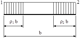
Figure 10-D.7‑1
Effective area calculation (![]() )
)
The effective area is determined from the effective cross section as shown in Figure 8a of the code (section 3.6.2.2).

Effective
modulus calculation (![]() )
)
The effective modulus is determined from the effective cross section as shown in Figure 8b of the code (section 3.6.2.3).
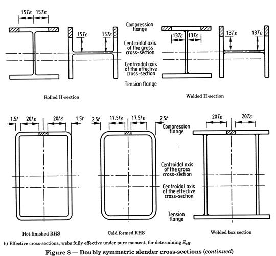
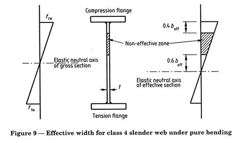
For cross sections with slender webs, the effective modulus is determined from the effective cross section as shown in Figure 9 of the code (section 3.6.2.4).
For circular hollow sections, the effective modulus and the effective area is determined according to the section 3.6.6 of BS 5950:2000.
b) Alternative Method (section 3.6.5)
As an alternative to the method previously described, a reduced design strength ryr is calculated as if the cross section were a class 3 semi-compact. This reduced design strength is used in place of ry in the checks of section capacity and member buckling resistance. The reduction factor fr is calculated for each section 4 element according to the below expression:

![]()
Where:
|
b3 |
Limiting value for a class 3 section according to the tables 11 and 12 of the code. |
|
b |
Width to thickness ratio for each element. |
10-D.7.3 Checking of Bending Moment and Shear Force (BS Article 4.2)
1. Forces and moments selection
The forces and moments considered for this checking type are:
|
|
Design value of the shear force perpendicular to the relevant axis of bending. |
|
|
Design value of the bending moment along the relevant axis of bending. |
2. Class determination and calculation either of the effective section properties or the design strength reduction factor for slender sections (depending on the selected method).
3. Criteria calculation
In members subjected to bending moment and shear force, three conditions should be checked:
3.1. Shear checking (Article 4.2.3 of BS 5950:2000)
The first condition to be checked is the shear criteria at each section:
![]() à
à ![]()
Where:
|
|
Design
value of the shear capacity:
|
|
|
Design strength of the material. |
|
|
Shear area. |
Shear Area Calculation (AV)
According to section 4.2.3 the shear area is calculated as follows:
Table 10-D.7‑1 Shear area
|
Shape |
Shear Area |
|
Rolled I, H and channel sections, load parallel to web. |
|
|
Welded I sections, load parallel to web. |
|
|
Solid bars and plates. |
|
|
Rectangular hollow sections, load parallel to webs. |
|
|
Welded box sections. |
|
|
Circular hollow sections. |
|
|
Any other case. |
|
where:
|
t |
Total web thickness. |
|
B |
Breadth. |
|
D |
Overall depth. |
|
d |
Depth of the web. |
|
A |
Area of the section. |
|
|
Area of the rectilinear element of the section which has the largest dimension in the direction parallel to the load:
|
In the case of biaxial bending, it is necessary to consider both shear areas, perpendicular to both the Standard’s X- and Y-axis.
3.2. Shear buckling resistance of thin webs (Article 4.4.5)
The shear buckling resistance should be checked if the ratio d/t of the web exceeds 70·e for a rolled section or 62·e for welded sections. It should satisfy the following criterion:
![]()
![]()
Where:
|
|
Shear buckling resistance (summation extended to all section webs). |
|
|
Critical shear strength. |
|
d |
Depth of the web. |
|
t |
Thickness of the web. |
The critical shear strength is obtained following the Appendix H.1 of the code
where
![]() and a is the distance between stiffeners. The ratio
and a is the distance between stiffeners. The ratio
d/a may be introduced by the user as a member property. By default, d/a = 1.
If the web of the section is not slender (d/t < 70·e for rolled sections and d/t
< 62·e for welded sections):
![]()
3.3. Bending moment check
Besides the shear checking, the following condition at each section is checked (Article 4.2.5 of BS 5950:2000):
![]() à
à ![]()
![]()
Where:
|
|
Moment capacity. |
|
Fr |
Stress reduction factor (only for the alternative method for slender sections). |
|
|
Bending resistant modulus. |
The reduction of the bending resistant modulus due to the effect of shear load is only applied if the shear load is above 60% of shear capacity of the section:
![]()
The bending resistant modulus is obtained by the following expressions:
1. If ![]()
a. For plastic or compact sections:
![]()
b. For semi-compact sections:
![]()
c. For slender sections:
![]()
2. If ![]()
a. For plastic or compact sections:
![]()
b. For semi-compact sections:
![]()
c. For slender sections:
![]()

Where:
|
Z |
Elastic resistant modulus of the section. |
|
|
Effective elastic modulus. |
|
S |
Plastic resistant modulus of the section. |
|
|
Effective plastic modulus. |
|
|
Plastic reduced modulus due to the effect of shear force. |
Sv Parameter Calculation
The ![]() calculation is done following the expression below:
calculation is done following the expression below:
![]()
Where:
|
S |
Plastic resistant modulus of the section: S |
|
|
Plastic modulus of the section remaining after deduction of the shear area: |
4. Calculation of the total criterion:
![]()
5. Output results are written in the CivilFEM results file (.RCV) as an alternative. Checking results: criteria and variables are described in the following table:
Tabla 10-D.7‑1 Art. 4.2 Checking of Bending Moment and Shear Force
|
Result |
Concepts |
Articles |
Description |
|
MX |
|
|
Design value of the bending moment |
|
MC |
|
4.2.5 |
Moment capacity |
|
FV |
|
|
Design value of the shear force |
|
PV |
|
4.2.3 |
Design value of the shear capacity |
|
CRT_V |
|
4.2.3 |
Shear criterion |
|
CRT_PV |
|
4.4.5 |
Buckling web criterion |
|
CRT_M |
|
4.2.5 |
Bending criterion |
|
CRT_TOT |
|
|
BS Global criterion |
|
CLASS |
|
3.5.2 |
Section class |
|
WEBCLASS |
|
3.5.2 |
Webs' Class |
|
MDF |
|
4.2.5 |
Plastic or elastic modulus of the section |
|
VW |
|
4.4.5 |
Shear buckling resistance |
10-D.7.4 Checking of Lateral Torsional Buckling Resistance (BS Article 4.3)
1.
Forces and moments selection.
The forces and moments considered in this check are:
|
|
Design value of the bending moment about the relevant axis of bending. |
2. Class determination.
3. Criteria calculation.
Resistance to lateral-torsional buckling need not be checked separately for the following cases:
· Bending about the minor axis
· Circular hollow sections (CHS), square RHS or circular or square solid bars
· I, H, Channel or Box sections, if equivalent slenderness (lLT) does not exceed the limiting equivalent slenderness (lL0)
· RHS, unless the slenderness exceeds the limiting value given in Table 15 of the code for the relevant value D/B.
Table 10-D.7‑2 Slenderness Limiting Value
|
D/B Depth / Width |
Limiting value of λ |
|
1.25 |
|
|
1.33 |
|
|
1.4 |
|
|
1.44 |
|
|
1.5 |
|
|
1.67 |
|
|
1.75 |
|
|
1.8 |
|
|
2 |
|
|
2.5 |
|
|
3 |
|
|
4 |
|
When checking for lateral torsional buckling of beams, the criterion shall be taken as:
![]()
Where:
|
|
Lateral torsional buckling resistance moment. |
|
|
Equivalent uniform moment factor for
lateral torsional buckling. This can be introduced as a member property
according to the table 18 of the code |
|
|
Maximum major axis bending moment. |
3.1 Determination of the buckling resistance moment Mb (Article 4.3.6.4)
The value of ![]() may be determined from the following:
may be determined from the following:
· For plastic and compact sections:
![]()
· For semi-compact sections:
![]()
· For slender sections:
![]()
Where ![]() is the bending strength.
is the bending strength.
If the equivalent slenderness ![]() is less than or equal to the limiting slenderness
is less than or equal to the limiting slenderness ![]() for the relevant design strength given in the tables 16 and 17 of
the code, then
for the relevant design strength given in the tables 16 and 17 of
the code, then ![]() should be taken as equal to
should be taken as equal to ![]() and no considerations for lateral torsional buckling will be
necessary.
and no considerations for lateral torsional buckling will be
necessary.
![]()
Otherwise the bending strength is obtained from the formula given in Appendix B.2.1 of the code:
For ![]()
![]()
![]()
Where hLT is the Perry coefficient
The Perry coefficient ![]() for lateral torsional buckling should be taken as follows:
for lateral torsional buckling should be taken as follows:
a) For rolled sections:
![]() with
with ![]()
b) For welded sections:
|
If |
|
|
If |
|
|
If |
|
|
If |
|
Where:
|
|
Limiting equivalent slenderness: |
|
|
Robertson constant, taken as 0.007. |
|
|
Equivalent slenderness. |

A. Equivalent Slenderness for I, H and Channel Sections
The equivalent slenderness ![]() is taken as follows:
is taken as follows:
![]()
The ratio ![]() depends on the section class:
depends on the section class:
·
For class 1 or 2 sections: ![]()
·
For class 3 sections: ![]()
·
For class 4 sections: ![]()

![]()
![]()
The buckling parameter u and the torsional index x are calculated as follows:
· For I and H sections

![]()
![]()
· For Channel sections


![]()
Where:
|
J |
Torsion constant (mechanical property of the section). |
|
|
Thickness of the compression flange. |
|
|
Thickness of the tension flange. |
|
|
Plastic modulus about the major axis. |
|
|
Moment of inertia about the major axis (mechanical property of the section). |
|
|
Moment of inertia about the minor axis (mechanical property of the section). |
|
A |
Cross sectional area (mechanical property of the section). |
|
H |
Warping constant (mechanical property of the section). |
The slenderness factor (v parameter) is given by:

![]()
Where:
|
|
Moment of area of the compression flange about the minor axis of the section. |
|
|
Moment of area of the tension flange about the minor axis of the section. |
|
|
Monosymmetry index, for I and T sections with lipped flanges. |
The monosymmetry index ![]() is calculated as follows:
is calculated as follows:
![]() for
for ![]()
![]() for
for ![]()
Where:
|
D |
Overall depth of the section (mechanical property of the section). |
|
DL |
Depth of the lip (introduced as a Member property). By default DL=0. |
B. Equivalent slenderness determination for Box Sections including RHS (Appendix B.2.6)
The equivalent slenderness, ![]() , for box sections is taken directly from the expression below:
, for box sections is taken directly from the expression below:
![]()

![]()
C. Equivalent slenderness determination for T sections (Appendix B.2.8)
The equivalent slenderness, ![]() , for T sections is obtained from the following:
, for T sections is obtained from the following:
a) If ![]() =
= ![]() : Lateral torsional buckling does not occur and
: Lateral torsional buckling does not occur and ![]()
b) If ![]() : Lateral torsional buckling occurs about the x-x axis and
: Lateral torsional buckling occurs about the x-x axis and ![]() is given by:
is given by:
![]()
c) If: ![]()
![]()
![]() Lateral torsional buckling occurs about the x-x axis and
Lateral torsional buckling occurs about the x-x axis and ![]() is given by:
is given by:
![]()


![]()
![]()
![]()
D. Equivalent slenderness determination for Equal Angle sections (Appendix B.2.9.1)
The equivalent slenderness, ![]() , for equal angle sections is obtained from the following:
, for equal angle sections is obtained from the following:
![]()

![]()
![]()
E. Equivalent slenderness determination for Unequal Angle sections (Appendix B.2.9.2)
The equivalent slenderness, ![]() , for unequal angle sections is obtained from the following:
, for unequal angle sections is obtained from the following:
![]()


The monosymmetry index ![]() for an unequal angle is taken as positive when the short leg is in
compression and negative when the long leg is in compression.
for an unequal angle is taken as positive when the short leg is in
compression and negative when the long leg is in compression.
![]() is the coordinate of the shear center along the v-v axis.
is the coordinate of the shear center along the v-v axis.
Table 10-D.7‑3 Art. 4.3 Checking of Lateral Torsional Buckling Resistance
|
Result |
Concepts |
Articles |
Description |
|
MB |
|
4.3.6 |
Buckling resistance moment |
|
UMLT |
|
4.3.6 |
Equivalent uniform moment |
|
M |
m |
|
Equivalent uniform moment factor |
|
LAMBDA |
Lambda |
B.2 |
Slenderness |
|
LAMBDALT |
LambdaLT |
B.2 |
Equivalent slenderness |
|
LAMBDALO |
LambdaLO |
B.2 |
Limiting equivalent slenderness |
|
CRT_TOT |
|
4.3.6 |
Global criterion |
|
CLASS |
|
3.5.2 |
Section class |
|
WEBCLASS |
|
3.5.2 |
Web class |
10-D.7.5 Checking of Members in Axial Tension (BS Article 4.6)
1.
Forces and moments selection.
The forces and moments considered for this checking type are:
|
|
Design value of the axial force (positive if tensile, element not processed if compressive). |
2. Class determination.
3. Criteria calculation.
For members under axial tension, the general criterion Crt_TOT is checked at each section. This criterion coincides with the axial criterion Crt_N:
![]() à
à ![]()
Where Pt is the
tension capacity: ![]()
4. Output results are written in the CivilFEM results file (.RCV) as an alternative. Checking results: criteria and variables are described in the following table:
Table 10-D.7‑4 Art. 4.6 Checking of Members in Axial Tension
|
Result |
Concepts |
Articles |
Description |
|
F |
F |
4.6.1 |
Tension Force |
|
PT |
|
4.6.1 |
Tension capacity |
|
CRT_TOT |
|
4.6.1 |
Global criterion |
10-D.7.6 Checking of Members in Axial Compression (BS Article 4.7)
1. Forces and moments selection.
The forces and moments considered for this checking type are:
|
|
Design value of the axial force (negative if it is compressive). If it is tensile, the element is not processed. |
2. Class determination.
3. Criteria calculation.
For members under axial compression, the general criterion Crt_TOT is checked at each section. This criterion coincides with the axial compression criterion Crt_CB:
![]() à
à ![]()
Where:
|
F |
Axial compression force. |
|
Pc |
Compressive strength for buckling. |
The compressive strength is determined according to the article 4.7.4 of BS 5950:2000:
· For class 1, 2 or 3 sections:
![]()
· For class 4 sections:
![]()
Where:
|
|
Gross sectional area. |
|
|
Effective cross sectional area. |
|
|
Compressive strength. |
|
|
Compressive strength for a reduced slenderness of |
The compressive strength may be obtained from (See Appendix C):

![]()
Where:
|
|
Design strength (reduced by 20N/mm2 for welded I, H or box sections). |
|
|
Euler strength: |
|
E |
Material elasticity modulus. |
|
|
Slenderness: |
|
|
Radius of gyration about the relevant axis. |
|
|
Effective buckling length: |
|
L |
Actual length of the member. |
|
|
Correction factors of buckling lengths for planes XZ and YZ. |

The Perry coefficient η for flexural buckling under load should be taken as follows (Appendix C.2):
![]()
Where ![]() is the limiting slenderness:
is the limiting slenderness:

The constant a (Robertson constant) is determined by the program from the type of section and buckling axis, according to the table 23 of the BS 5950:2000. Therefore, if the user introduces a value for this constant in member properties, the program will give precedence to the user’s value.
|
a= |
2.0 for curve (a) |
|
a= |
3.5 for curve (b) |
|
a= |
5.5 for curve (c) |
|
a= |
8.0 for curve (d) |
To distinguish between I and H shapes the program follows the criteria below:
I shapes if ![]()
H shapes if ![]()
4. Output results are written in the CivilFEM results file (.RCV) as an alternative. Checking results: criteria and variables are described in the following table.
Table 10-D.7‑5 Art. 4.7 Checking of Members Axial Compression
|
Result |
Concepts |
Articles |
Description |
|
F |
F |
4.7 |
Compression Force |
|
PC |
|
4.7.4 |
Compression capacity |
|
RHOC |
|
4.7.5 |
Compression Resistance |
|
LAMBDA |
Lambda |
4.7.2 |
Slenderness |
|
LAMBDA0 |
Lambda0 |
C.2 |
Limiting slenderness |
|
PERRYFCT |
NU |
C.2 |
Perry factor |
|
ROBERSTS |
a |
C.2 |
Robertson constant |
|
CRT_TOT |
|
4.7 |
Global criterion |
|
WEBCLASS |
|
3.5.2 |
Web class |
|
CLASS |
|
3.5.2 |
Section class |
10-D.7.7 Tension Members with Moments (BS Article 4.8.2)
4. Forces and moments selection.
The forces and moments considered for this checking type are:
|
|
Design value of the axial force. |
|
|
Design value of the bending moment along the primary bending axis. |
|
|
Design value of the bending moment about the secondary bending axis. |
5. Class determination.
6. Criteria calculation.
For members subjected to an axial tension force and bending moments, each section should be checked according the same conditions for members subjected to a shear force and bending moments (see section 9.8.3 of this manual).
Therefore, for this type of checking, the following conditions are checked:
3.1 Shear checking in both directions
![]()
![]()
Where ![]() and
and ![]() are the shear forces about X and Y axis, and
are the shear forces about X and Y axis, and ![]() and
and ![]() the shear capacity about X and Y axis.
the shear capacity about X and Y axis.
3.2 Shear buckling resistance of shear webs
![]()
![]()
Where Vwx and Vwy are the shear buckling resistance about X and Y axis, respectively.
![]()
![]()
3.3 Checking of axial force and bending moments
Each section is checked according to the following condition:

Equivalent to:
Crt_CMP = Crt_AXL + Crt_Mx + Crt_My £ 1
![]()
![]()

Where:
|
F |
Axial force. |
|
|
Bending moment about major axis. |
|
|
Bending moment about minor axis. |
|
|
Effective net area of the section. |
|
|
Design strength of the material. |
|
|
Moment capacity about major axis. |
|
|
Moment capacity about minor axis. |
![]() and
and ![]() are calculated according to the Article 4.2.5 of BS 5950:2000.
are calculated according to the Article 4.2.5 of BS 5950:2000.
For this checking type (moments on both directions), the shear area, the plastic modulus and the Sv parameter are calculated with respect to both directions (X and Y axis).
3.3 Checking of global criterion
![]()
4. Output results are written in the CivilFEM results file (.RCV) as an alternative. Checking results: criteria and variables are described in the following table.
Table 10-D.7‑6 Art. 4.8.2 Checking of Tension Members with Moments
|
Result |
Concepts |
Articles |
Description |
|
F |
F |
|
Axial tension force |
|
MX |
|
4.2.5 |
Bending moment about major axis |
|
MY |
|
4.2.5 |
Bending moment about minor axis |
|
FVX |
|
|
Shear force about major axis |
|
FVY |
|
|
Shear force about minor axis |
|
PVX |
|
4.2.3 |
Shear capacity about major axis |
|
PVY |
|
4.2.3 |
Shear capacity about minor axis |
|
PT |
|
4.6.1 |
Axial Tension Capacity |
|
MCX |
|
4.2.5 |
Moment capacity about major axis |
|
MCY |
|
4.2.5 |
Moment capacity about minor axis |
|
CRT_AXL |
|
4.6.1 |
Axial Criterion |
|
CRT_VX |
|
4.2.3 |
Shear Criterion about major axis |
|
CRT_VY |
|
4.2.3 |
Shear Criterion about minor axis |
|
CRT_MX |
|
4.2.5 |
Bending Criterion about major axis |
|
CRT_MY |
|
4.2.5 |
Bending Criterion about minor axis |
|
CRT_PVX |
|
4.4.5 |
Buckling web Criterion about major axis |
|
CRT_PVY |
|
4.4.5 |
Buckling web Criterion about minor axis |
|
CRT_CMP |
Crt_AXL + Crt_MX + Crt_MY |
4.8.2 |
Axial + moments Criterion |
|
SVX |
|
4.2.6 |
Sv parameter for major axis |
|
SVY |
|
4.2.6 |
Sv parameter for minor axis |
|
CRT_TOT |
|
4.8.2 |
Global criterion |
|
AVX |
|
4.2.3 |
Shear Area for major axis |
|
AVY |
|
4.2.3 |
Shear Area for minor axis |
|
VWX |
|
4.4.5 |
Shear buckling resistant for major axis |
|
VWY |
|
4.4.5 |
Shear buckling resistant for minor axis |
|
MDFX |
|
4.2.6 |
Resistant modulus for major axis |
|
MDFY |
|
4.2.6 |
Resistant modulus for minor axis |
|
ZX |
|
4.2.6 |
Elastic Modulus about major axis |
|
SX |
|
4.2.6 |
Plastic Modulus about major axis |
|
ZY |
|
4.2.6 |
Elastic Modulus about minor axis |
|
SY |
|
4.2.6 |
Plastic Modulus about minor axis |
|
CLASS |
|
3.5.2 |
Sections class |
|
WEBCLASS |
|
3.5.2 |
Web’s class |
10-D.7.8 Compression Members with Moments (BS Article 4.8.3)
1. Forces and moments selection.
The forces and moments considered for this checking type are:
|
|
Design value of the axial force. |
|
|
Design value of the shear force perpendicular to the primary bending axis. |
|
|
Design value of the shear force perpendicular to the secondary bending axis. |
|
|
Design value of the bending moment along the primary bending axis. |
|
|
Design value of the bending moment about the secondary bending axis. |
2. Class determination.
3. Criteria calculation.
Compression members are checked for local capacity at the points of greatest bending and axial load. This capacity may be limited by either yielding or local buckling, depending on the section properties. The member is then checked for global buckling.
Therefore, for this type of checking, the following conditions are checked:
3.1 Local Capacity Check
3.1.1 Axial Criterion
![]()
Where:
|
F |
Axial load |
|
|
Compression capacity: For
class 1, 2 or 3 sections: For
class 4 sections: |
3.1.2 Local criteria as for Tension Members with Moments
Bending criterion (major axis)= Crt_MX_L
Bending criterion (minor axis)= Crt_MY_L
Shear criterion about major axis= Crt_VX
Shear criterion about minor axis = Crt_VY
Buckling web Criterion about major axis = Crt_PVX
Buckling web Criterion about minor axis = Crt_PVY
3.1.3 Component Local Criterion
4
![]()
4.1 Overall Buckling Check
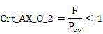
4.1.1 Axial Criterion (Buckling)
![]()
Where:
|
F |
Design value of the axial compressive force. |
|
|
Compression resistance. |
|
|
Compresion resistance, considering buckling about the minor axis only: For
class 1, 2 or 3 sections: For class 4 sections: |
|
|
Gross sectional area. |
|
|
Compressive strength obtained according article 4.7.5 of the code. |
4.1.2 Bending Moment Criterion (primary axis)

![]()
Where:
|
|
Equivalent uniform moment factor. Introduced as a member property.
By default |
|
|
Equivalent uniform moment factor for lateral torsional buckling.
Introduced as a member property. By default |
|
|
Bending moment about major axis. |
|
|
Buckling resistance moment according the article 4.3 of the code. |
|
|
Maximum major axis moment . |
4.1.3 Bending Moment Criterion (secondary axis)

Where:
|
|
Equivalent uniform moment factor. Introduced as a member property.
By default |
|
|
Bending moment about minor axis. |
|
|
Elastic modulus about the minor axis (for slender class 4 sections
|
4.1.4 Component Global Criterion
![]()

![]()

![]()
![]()
4.2 Total Criterion
![]()
4. Output results are written in the CivilFEM results file (.RCV) as an alternative. Checking results: criteria and variables are described in the following table.
Table 10-D.7‑7 Art. 4.8.3 Checking of Compression Members with Moments
|
TABLE |
Concepts |
Articles |
Description |
|
F |
F |
|
Design value of the axial compressive force |
|
PC |
|
4.7.4 |
Compression resistance |
|
FVX |
|
|
Shear force about major axis |
|
MX |
|
|
Bending moment about major axis |
|
ZX |
|
4.2.5 |
Elastic Modulus about major axis |
|
SX |
|
4.2.5 |
Plastic Modulus about major axis |
|
SVX |
|
4.2.5 |
Sv parameter for major axis |
|
AVX |
|
4.2.3 |
Shear Area for major axis |
|
VWX |
|
4.4.5 |
Shear buckling resistant for major axis |
|
MDFX |
|
4.2.5 |
Resistant modulus for major axis |
|
PVX |
|
4.2.3 |
Shear capacity about major axis |
|
MCX |
|
4.2.5 |
Moment capacity about major axis |
|
FVY |
|
|
Shear force about minor axis |
|
MY |
|
|
Bending moment about minor axis |
|
ZY |
|
4.2.5 |
Elastic Modulus about minor axis |
|
SY |
|
4.2.5 |
Plastic Modulus about minor axis |
|
SVY |
|
4.2.5 |
Sv parameter for minor axis |
|
AVY |
|
4.2.3 |
Shear Area for minor axis |
|
VWY |
|
4.4.5 |
Shear buckling resistant for minor axis |
|
MDFY |
|
4.2.5 |
Resistant modulus for minor axis |
|
PVY |
|
4.2.3 |
Shear capacity about minor axis |
|
MCY |
|
4.2.5 |
Moment capacity about minor axis |
|
M |
M |
4.8.3.3 |
Equivalent uniform moment factor |
|
LAMBDA |
Lambda |
4.3.7.5 |
Slenderness |
|
LAMBDA0 |
Lambda0 |
C.2 |
Limiting slenderness |
|
LAMBDALT |
LambdaLT |
4.3.7.5 |
Equivalent slenderness |
|
LAMBDAL0 |
LambdaL0 |
B.2.4 |
Limiting equivalent slenderness |
|
PERRYFCT |
NU |
C.2 |
Perry Factor |
|
MB |
|
4.3.7 |
Buckling resistance moment capacity |
|
CRT_TOT |
Max(Crt_CM_L, Crt_CM_O, Crt_VX, Crt_VY, ...) |
4.8.3 |
Total Criterion |
|
CRT_CM_L |
Crt_AX_L + Crt_MX_L + Crt_MY_L |
4.8.3 |
Local Axial + moments Criterion |
|
CRT_CM_O |
Crt_AX_O + Crt_MX_O + Crt_MY_O |
4.8.3 |
Global Axial + moments Criterion |
|
CRT_AX_L |
|
4.8.3 |
Local axial criterion |
|
CRT_MX_L |
|
4.2.5 |
Local bending moment criterion about X axis |
|
CRT_MY_L |
|
4.2.5 |
Local bending moment criterion about Y axis |
|
CRT_AX_O |
|
4.8.3 |
Global axial criterion |
|
CRT_MX_O |
|
4.8.3 |
Global bending moment criterion about X axis |
|
CRT_MY_O |
|
4.8.3 |
Global bending moment criterion about Y axis |
|
CRT_VX |
|
4.2.3 |
Shear criterion about X axis |
|
CRT_PVX |
|
4.4.5 |
Buckling web Criterion about major axis |
|
CRT_VY |
|
4.2.3 |
Shear criterion about Y axis |
|
CRT_PVY |
|
4.4.5 |
Buckling web Criterion about minor axis |
|
CLASS |
Class |
3.5.2 |
Section Class |
|
WEBCLASS |
Webclass |
3.5.2 |
Web’s Class |